Stability of Milling Process with Variable Spindle Speed Using Runge–Kutta-Based Complete Method
Abstract
The variable-spindle-speed (VSS) technique is effective in preventing regenerative chatter in milling processes. However, spindle-speed-modulation parameters should be deliberately selected to augment the material removal rate. Stability-prediction algorithms of stability predicting play an important role in this respect, as they allow the prediction of stability for all ranges of a given spindle speed. The increase in calculation time in variable-spindle-speed milling, which is caused by the modulation frequency, hinders its practical use in the workshop. In this paper, a Runge–Kutta-based complete discretization method (RKCDM) is presented to predict the stability of milling with variable spindle speeds, which is described by a set of delay differential equations (DDEs) with time-periodic coefficients and time-varying delay. The convergence and calculation efficiency are compared with those of the semidiscretization method (SDM) under different testing configurations and milling conditions. Results show that RKCDM is more accurate and saves at least 50% of the calculation time of SDM. The effects of modulation parameters on the stability of VSS milling are explored through stability lobe diagrams produced from RKCDM.
1. Introduction
In the milling process, chatter caused by vibrations between the cutter and workpiece hinders manufacturing production. It cannot only reduce machining performance, but can cause a poor workpiece-surface finish, increase tool wear, and decrease the lifetime of the machine tool itself.
Chatter is generally classified in two categories. Primary chatter is usually triggered by friction between the cutter and the workpiece. Secondary chatter, which is caused by a regenerative mechanism, is most common factor. That is why many publications discuss only regenerative chatter.
- (1)
Strategies based on a stability lobe diagram (SLD) and the selection of cutting parameters
- (2)
Active chatter-suppression techniques to decrease the vibration of a machine tool system
- (3)
Semiactive chatter-suppression strategies
- (4)
Passive chatter-suppression strategies accounting for a machine tool’s compliance or configuration
- (5)
Other strategies based on signal surveillance in the milling process for the adjustment of milling parameters
SLD is the most logical and widely accepted method to select cutting parameters to avoid chatter. Researchers have proposed numerous methods to predict machining stability. These include the zero-order frequency method [1], numerical integration method [2], temporal finite element analysis (TFEA) [3], semidiscretization method (SDM) [4, 5], semidiscretization method on a Shannon standard orthogonal basis [6, 7], Lambert W function-based method [8], Legendre polynomial-based method [9], Adams–Simpson-based method [10], Runge–Kutta-based complete discretization method [11], and Chebyshev collocation method for delay differential equations [12].
Because regenerative chatter is a result of improper phase differences between undulate surfaces caused by successive cuts by a tool, alternative methods usually vary the time lag between cutter teeth. Slavicek [13] demonstrated that this can be achieved through variable-pitch cutters. Altintas et al. [14], Olgac and Sipahi [15], Jin et al. [16], and Sims et al. [17] all demonstrated that variable-pitch cutters can avoid or significantly suppress chatter.
The idea of changing the spindle speed to suppress or avoid chatter in machining dates back to the 1970s and the pioneering research of Stoferle and Grab [18]. After that, Takemura et al. [19] studied the stability of variable-spindle-speed turning, and experimental tests showed only small improvements in the depth of cuts, although the stability of VSS was higher than that of constant-spindle-speed (CSS) milling. Altintas and Chan [20] investigated the stability of VSS with sinusoidal modulation using a time-simulation method. Tsao et al. [21] described the VSS milling system in the angle domain and showed that chatter could be suppressed or eliminated to a great extent by properly selecting the modulation parameters. Long and Balachandran [22] analyzed the stability of up- and down-milling with sinusoidal modulation using the semidiscretization method. In the frequency domain, Zatarain et al. [23] proposed a general theory to analyze the stability of VSS milling. Seguy et al. [24, 25] used a semidiscretization method to study the stability of VSS milling in the high-speed domain and reported that VSS was an effective method to reduce period-doubling chatter. Based on the full-discretization method, Xie and Zhang [26, 27] presented an improved SDM to predict the stability of VSS milling. Ding et al. [28] studied the stability of the VSS milling system using the constant-step numerical method. Niu et al. [29] unified different periodic time-variant spindle-speed-modulation schemes in a unique framework, derived and calculated the time-varying delay based on the fourth-order Runge–Kutta method, and calculated and compared the stability of VSS milling with different modulation schemes using variable-step numerical integration. Totis et al. [30] studied the stability of milling with VSS in the angular domain. Jin et al. [31] studied the stability of milling with constant pitch, variable pitch, and VSS, using a full-discretization method.
As mentioned above, much research has been done to predict the stability of VSS milling. However, the required computational time increases greatly due to frequency modulation, and this hinders the application of VSS [29]. Niu et al. [32] and Li et al. [11] recently proposed a Runge–Kutta-based complete discretization method (RKCDM) using complete discretization scheme [33], but their research was based exclusively on CSS machining. In this paper, we present a two-degree-of-freedom dynamic milling model expressed by DDEs and a Runge–Kutta-based complete discretization method for efficient analysis of VSS milling. The convergence and computational efficiency are compared with a state-of-the-art semidiscretization method. Finally, we discuss the VSS modulation effects on the stability of milling with the aid of maps and contour plots of axial depth of cut (ADOC) calculated by RKCDM.
2. Modeling of VSS Process
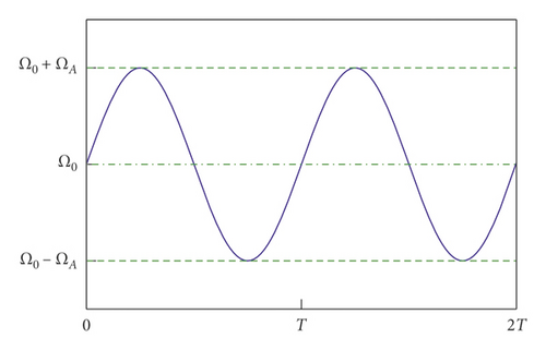
2.1. VSS
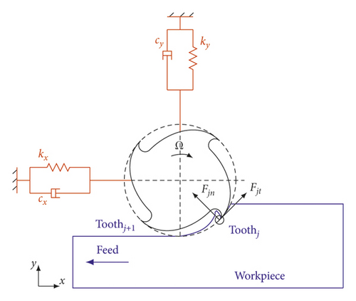
2.2. Structural Model
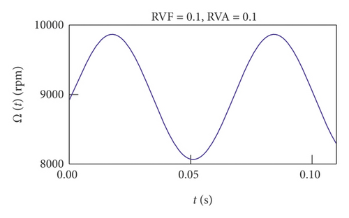
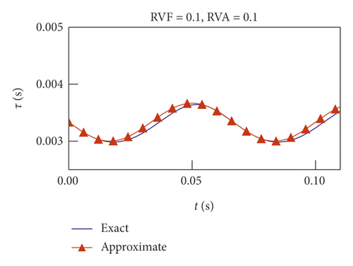
2.3. Calculation of Variable Time Delays
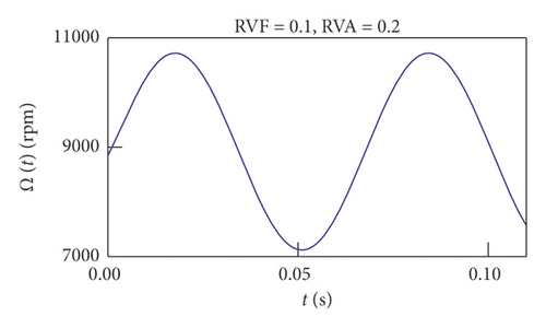
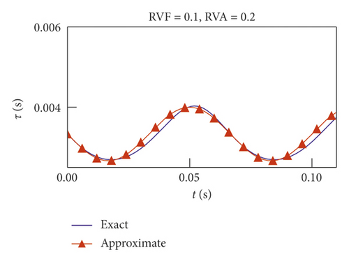
3. Stability of Milling with VSS
Note that M can be considered an approximation parameter regarding the length of the time delay.
Then, the stability of the system can be calculated based on the Floquet theory. If the moduli of all eigenvalues of the transition matrix Φ are less than unity, then the system is stable; otherwise, it is unstable.
4. Simulation and Discussion
In this section, an experimental example [3] is used to verify the accuracy and efficiency of RKCDM. The modal parameters of the milling systems are tool diameter D = 12.7, number of teeth N = 2, tangential cutting force coefficient Kt = 6 × 10⁸ N/m2, radial cutting force coefficient Kn = 2 × 10⁸ N/m2, natural frequency ωnx = ωny = 922.0 Hz, modal damping ratio ζx = ζy = 0.011, and modal mass mtx = mty = 0.03993 kg. All calculations are performed in MATLAB R2014a on a desktop computer (Intel Core (TM) i7-6700K central processing unit, 4.0 GHz, 16 GB). We first discuss the convergence of RKCDM and SDM.
4.1. Convergence and Computation Efficiency
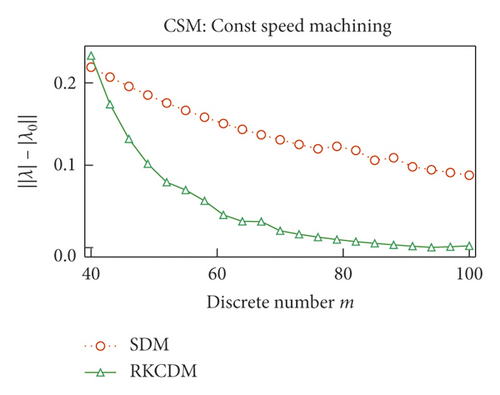
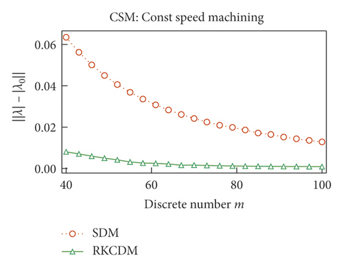
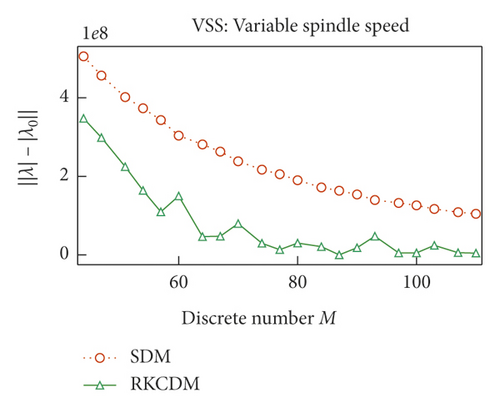
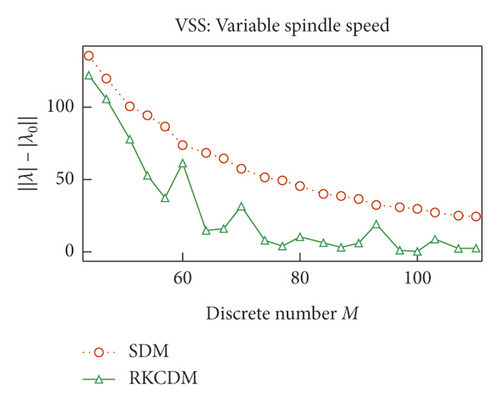
The convergence rates of RKCDM and SDM with different conditions are compared in Figure 4. The discrete number of time delays τ (τ(t) for VSS milling) is set as m for constant-speed milling and M for VSS milling and is determined according to (17), and the maximal module of the eigenvalues of the transition matrix Φ is set as λ. To compare the convergence of RKCDM and SDM, the value of λ under condition of m = 500 is written as λ0 as the exact value to assess its convergence rate. When m increases, the approximation error of RKCDM is lower than SDM. The same phenomenon can be obtained for VSS milling with the increase of M. This means that RKCDM converges faster than SDM with the increase of the discrete number of time delays, because for SDM, the discretization error is O(h)2 [36]. However, discretization error for RKCDM is O(h)5. Niu et al. [32] used two-point barycentric Lagrange points to approximate the middle points, so the remainder of the two-point interpolation is O(h)2. To increase the accuracy of RKCDM, 2k discrete points are taken in one tooth-passing interval to calculate cutting-force coefficients hxx(t), hxy(t), hyx(t), and hyy(t) for the following examples. So, at time interval [ti, ti+1], Ai, Ai+1, Bi, and Bi+1, can be calculated using even points, and Ai+0.5 and Bi+0.5 are calculated using the left points. The benefit of this is that the accuracy of RKCDM is the same with the classical fourth-order Runge–Kutta method. To improve the prediction accuracy, the discrete number M of time-varying delays τ(t) is always greater than 80, and according to Figure 4, RKCDM can have the minimum approximation error.


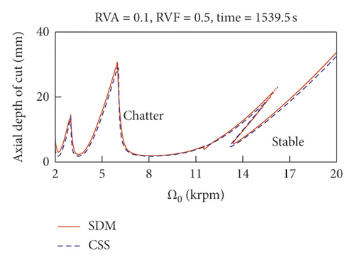
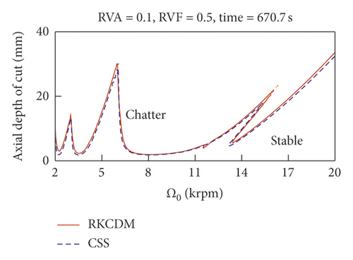
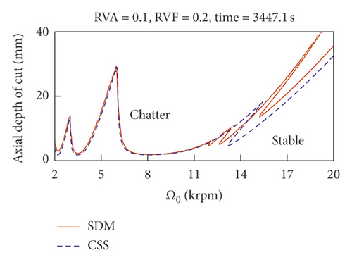
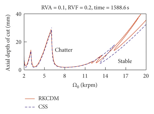
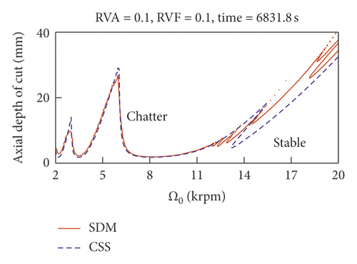
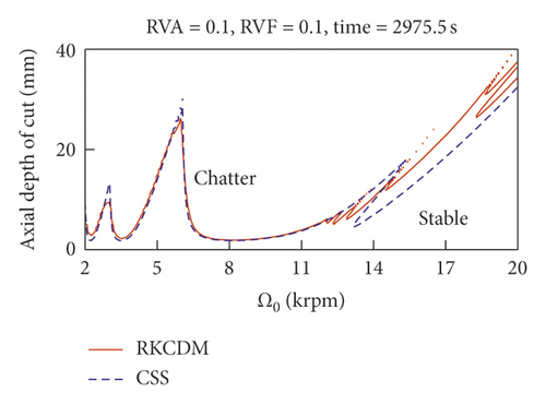
To compare the computational efficiency, we refer to Figure 5, which shows the time consumption using RKCDM and SDM. For VSS milling, the consumption time to achieve stability increases as RVA decreases. For small RVA, more time can be saved with RKCDM than with SDM. Hence, we conclude that the time consumption increases with the number of discrete time delays. The results of Figure 5 indicate that 54% of time consumption can be saved using RKCDM instead of SDM.
4.2. Analysis of Effect of Modulation Parameters on Stability of VSS Milling
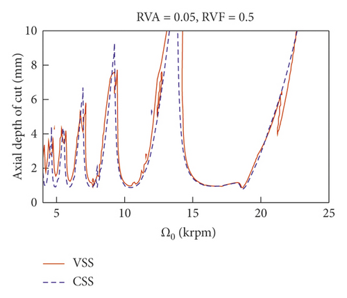
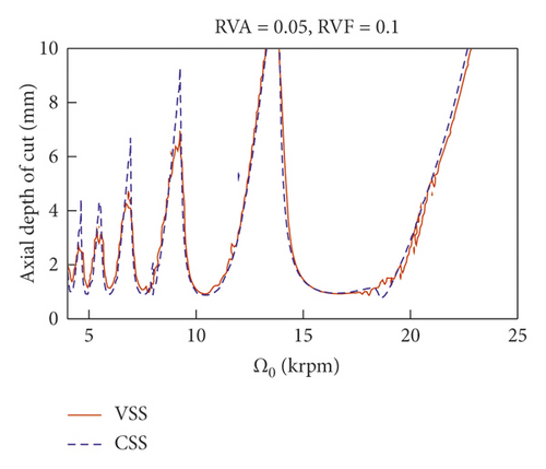
Figure 6 shows the SLD of VSS and CSS milling. Using VSS, the stability boundary obviously increases, especially at low spindle speeds. Although the depth of cut increases using VSS, the modulation also has an important effect on the stability. Taking Figure 6(a) as an example, the depth of cut around nominal spindle speed 22,000 rpm decreases abruptly. To comprehensively explore the effects of modulation parameters on the stability of milling, the relationships among depth of cut, RVA, and RVF are shown in the 3D plots of Figures 7 and 8. According to Figure 6(a), the axial depth of cut has a minimum value of 1 mm for CSS milling.
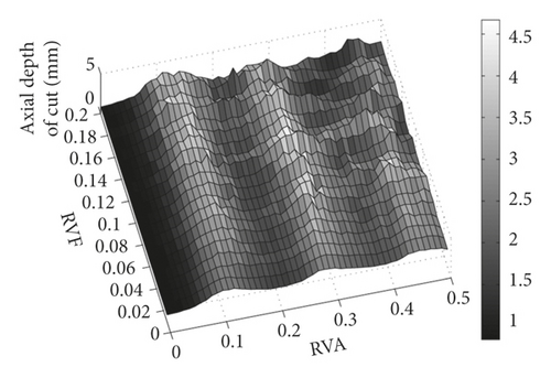
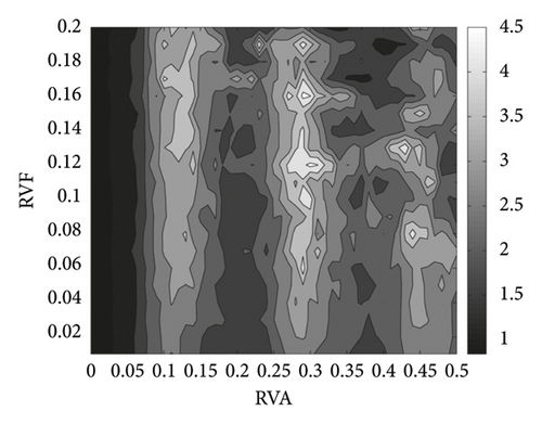
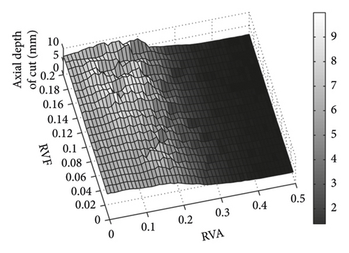
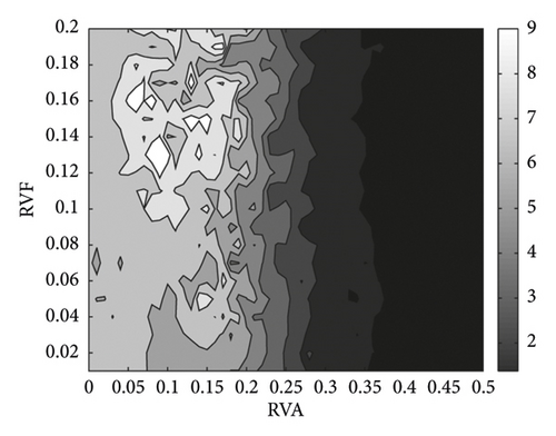
After VSS is used, the ADOC at these two nominal spindle speeds increases significantly, as illustrated in Figures 7 and 8. Figure 7 shows that the ADOC changes with the variation of sinusoidal modulation parameters RVA and RVF around a nominal spindle speed of 4,900 rpm. Obviously, when VSS is used, the lowest point is higher than that of CSS milling. From Figure 7, we know that the ADOC is more sensitive to RVA than to RVF; so, for the machinist, the selection of modulation parameters is more interesting than that of spindle speed. Taking a nominal spindle speed of 4,900 rpm as an example, with modulation parameters RVA = 0.10 and RVF = 0.17, ADOC will increase to 4.16 mm. The contour plot in Figure 7(b) shows that not only at the vicinity of point (0.10, 0.17) but also all stable ADOC limit in these two figures (Figures 7 and 8) are greater than 1 mm too. So, VSS can always increase the ADOC around the nominal spindle speed of 4,900 rpm. When RVA is in the range [0.26, 0.33], the ADOC can still achieve a local maximum. Because the selection of RVA is constrained by the driving power of the spindle speed, a low RVA is more adaptable for VSS milling.
The results at a nominal spindle speed of 22,000 rpm differ from those at 4,900 rpm. ADOC drops abruptly around a nominal spindle speed of 22,000 rpm. To explore the effects of the VSS technique on the stability of milling, we show a three-dimensional stability diagram at a nominal spindle speed of 22,000 rpm in Figure 8. With VSS, ADOC is always higher than CSS in Figure 7. However, this is different at a nominal spindle speed of 22,000 rpm, where ADOC does not always increase with VSS milling over CSS milling. Figure 6 shows that ADOC is 7.83 mm without VSS. In Figure 8, ADOC is always lower than 7.83 mm with RVA in the range [0.2, 0.3]. So, it is important to choose modulation parameters appropriately to improve stability with the VSS technique. In Figure 8, ADOC increases to a local summit with the variation of RVA and RVF, such as around RVA = 0.06 and RVF = 0.16, RVA = 0.08 and RVF = 0.13, and RVA = 0.14 and RVF = 0.15. Taking RVA = 0.06 and RVF = 0.16 as an example, the ADOC can reach 9.99 mm in this area. So, ADOC can still be increased with appropriate selection of modulation parameters.
5. Conclusion
- (1)
The governing DDE of the time-periodic milling process including the regenerative effect is described by a set of algebraic equations, and the stability of the system is predicted by the Floquet theory.
- (2)
Comparisons of convergence rate and computational efficiency were conducted. RKCDM shows a higher convergence rate than SDM, so RKCDM is more accurate.
- (3)
Simulation results indicate that RKCDM can be used for parameter selecting in VSS milling. The maps and contour plots of ADOC produced from RKCDM show the stability of VSS milling with sinusoidal modulation changes with RVA and RVF, and the stability is more sensitive to variation in RVA. The maps and contour plots of ADOC can be used to select the optimal modulation parameters for VSS milling.
Finally, although the optimal parameters of the VSS technique have been selected through the method proposed here, it is obvious that the parameters should be further tested, and this will be our future work.
Conflicts of Interest
The authors declare no conflicts of interest.
Acknowledgments
This work was financially supported by the Science and Technology Commission of Shanghai Municipality (17DZ2283300).
Open Research
Data Availability
The data used to support the findings of this study are included within the article.


