Prototype Test and Numerical Analysis of a Shallow Cable with Novel Viscous Inertial Damper
Abstract
As an essential component of offshore bridges, stay cables are prone to vibrations due to their low inherent damping characteristics. Various dampers have been used for cable vibration control; however, the experimental research and theoretical study of inertial dampers on real cables have not been conducted sufficiently. This study aims to investigate the damping performance of a novel viscous inertial damper (VID) and focuses on the frequency-dependent and displacement amplification phenomena of a cable-damper system. Tests were first conducted to verify the energy consumption capacity of a prototype damper. A shallow cable-VID system was established. Theoretically, complex-valued modes were analyzed to determine the influence of the inertial and viscous coefficients on the cable’s frequency and mode damping ratio. The test results and numerical analysis show that the VID has a good damping effect on the shallow cable. Considering multiple adjacent cable modes, the inertial and viscous coefficients can be optimized. After optimizing, the VID can simultaneously maximize both adjacent symmetric and antisymmetric modes’ damping ratios. The two frequencies are almost the same. The displacement amplification of the VID shows that a VID can overcome the shortcomings of displacement loss caused by traditional oil dampers. The implications of these findings of the VID on shallow cable are discussed, which will guide future research and applications of the VID or other inerter dampers.
1. Introduction
As an essential component of the offshore cable-stayed bridge, cables have high flexibility and low inherent damping. Vibration problems can be frequently encountered in these bridges, such as vortex-induced vibrations, parametric resonance, wake galloping, buffeting, and wind-and rain-induced vibrations [1–9]. These problems affect the public’s confidence in the bridge’s structural safety and shorten the cables’ service life. Long-span cable-stayed bridges adopt various cable vibration control measures. The additional external viscous damper can directly increase the cable’s mode damping ratio, which is the most common cable vibration control method. The design theory and vibration control methods of stayed cables have been extensively studied [10–16]. Passive viscous dampers solve the vibration problem of cables to some extent, but the installation location restricts the damper’s damping effect. The installation location does not exceed 5% of the cable length [17, 18], so the additional damping ratio provided may be limited. Additionally, parameters such as the sag, bending stiffness, damper support stiffness, internal stiffness, and the coupled vibration between the cable and the beam will reduce the damping effect [15, 19]. Besides, external viscous dampers only achieve the optimal damping ratio for a specific vibration mode of cables. Generally, many factors dramatically limit the viscous damper’s damping effect.
In the process of studying active and semiactive dampers, researchers have found that negative stiffness can make the damper move with greater displacement, consume more energy, and achieve a higher damping ratio [20–25]. By using mechanical amplification mechanisms (such as ball screws, gears, and lever pendulums), inertial devices can provide a larger apparent mass, and inertial force is gradually used for structural vibration control. Lazar et al. [26–28] replaced the mass part of a tuned mass damper with an inertial mass and constructed a tuned inertial damper (TID). Vibration control analysis of the cable’s first vibration mode showed that the TID makes the cable obtain a higher mode damping ratio than the traditional viscous damper. Chen et al. [29] applied a passive negative stiffness device for the cable-damper system to overcome the problem of insufficient additional damping and discussed the influence of the nonlinear control force caused by negative stiffness. Shi et al. [30–33] proposed a negative stiffness damper composed of magnets that provides negative stiffness and an oil damper. Numerical analysis and experiments verified that the damper’s damping performance for the first vibration mode of the cable is much better than that of the traditional viscous damper. Nakamura et al. [34] and Wang et al. [35] developed an electromagnetic inertial mass damper (EIMD) using a rotary electromagnetic damper and ball screw inertial devices, respectively. Through the displacement enhancement mechanism of the ball screw, EIMD makes the flywheel produce larger inertial mass than its physical mass. Simultaneously, it has an acceleration effect on the rotary electromagnetic damper’s rotational speed, and the inertial coefficient and damping coefficient work synergistically. At present, the research on using inertial mass to reduce cable vibration is still in its infancy, and most scholars have only conducted theoretical research.
This study aimed to undertake more diversified vibration system research to realize cable vibration control using viscous and inertial devices. Both numerical and experimental solutions were obtained for a shallow cable with a viscous inertial damper (VID) installed close to a cable end. The understanding gained will help with interpreting cable vibration control using VIDs or other inertial devices, which can provide outstanding damping performance and understand the frequency-dependent and displacement amplification mechanism of the shallow cable-VID system. Subsequently, three different cases of inertial devices were established to experimentally verify the accuracy of the numerical analysis and validate the superior vibration mitigation performance of the VID. Finally, the most practical motivation of this study was to conduct a refined investigation and construct an achievable method for vibration control on cable structures.
2. Novel Viscous Inertial Damper
2.1. Composition and Mechanical Parameters of VID
2.2. Inertial Coefficient
2.3. Viscous Coefficient
2.4. Calculation of Damping Force
3. Mechanical Properties of VID
At present, the main method to understand the mechanical properties of dampers is the force-displacement curve. In this study, the mechanical performance of the damper under different cases (different inertial mass and different frequency) is studied through the vibration signal measured by the force sensor and the laser displacement sensor equipment on the end of the rack.
3.1. Damper’s Parameters
The parameters of the damper’s pinion, shaft, damping disc, rack, and inertial disc are calculated according to equations (4)–(6) and summarized in Tables 1 and 2.
| Component | Physical mass, M (kg) | Amplification factor, n | Inertial mass, bd (kg) |
|---|---|---|---|
| Pinion, n1 | 0.2387 | 0.5017 | 0.1198 |
| Shaft, n2 | 1.1098 | 0.1037 | 0.1150 |
| Viscous disc, n3 | 0.6045 | 2.6421 | 1.5976 |
| Rack, n4 | 2.4010 | 1 | 2.4010 |
| Inertial disc 1, n51 | 1.6350 | 3.5376 | 5.7839 |
| Inertial disc 2, n52 | 2.7250 | 5.9340 | 16.1701 |
| Damper part | Pinion + Shaft + Rack + Damping disc | Pinion + Shaft + Rack + Damping disc + Inertial disc 1 | Pinion + Shaft + Rack + Damping disc + Inertial disc 2 |
|---|---|---|---|
| Inertial mass bd | 4.2334 | 10.0173 | 20.4035 |
3.2. Test Results and Analysis
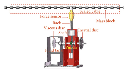
This study added damping fluid to the tank and installed the damping disc on the shaft. The rotation of the damping disc in the damping fluid plays the role of shearing the fluid, since the disc has certain inertia. Simultaneously, it also plays a role in providing negative stiffness. If it is necessary to increase the inertia, the inertial disc can be added on the other end of the shaft outside the tank.
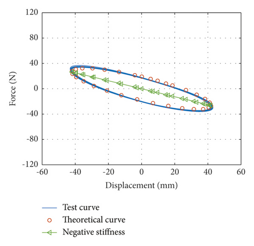
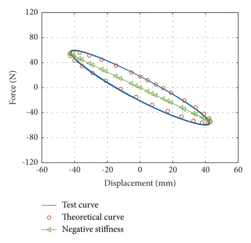
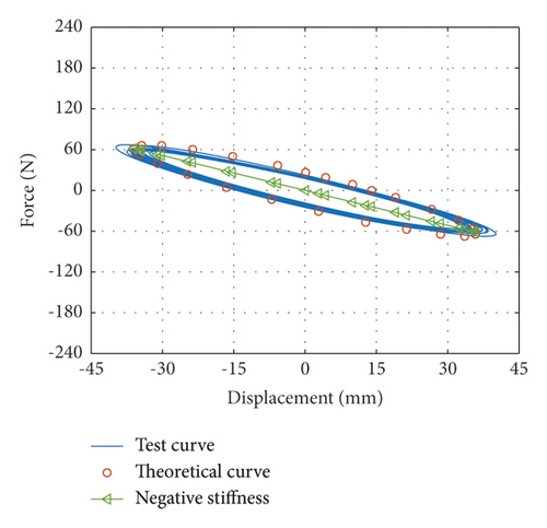
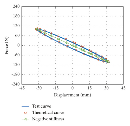
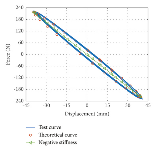
When the vibration frequencies are 1.92 Hz, 1.77 Hz, and 1.55 Hz, inertial mass bd of the damper is 4.2334 kg, 10.0173 kg, and 20.4035 kg, respectively, which are named Case 1, case 2, and case 3, respectively. Force-displacement curves obtained from tests under Case 1 and corresponding theoretical force-displacement curves are shown in Figure 2(a). Force-displacement curves obtained from tests under case 2 and corresponding theoretical force-displacement curves are shown in Figure 2(b). Force-displacement curves obtained from tests under case 3 and corresponding theoretical force-displacement curves are shown in Figure 2(c). The theoretical force-displacement curves are calculated according to equation (10), nearly equal to the envelope areas and negative slope of the test force-displacement curves.
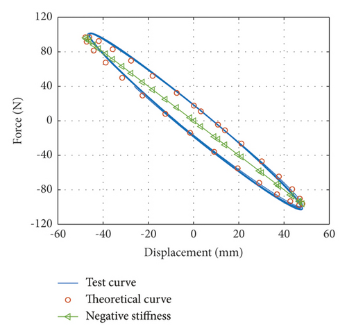
When the vibration frequencies are 3.17 Hz, 2.77 Hz, and 2.59 Hz, inertial mass bd of the damper is 4.2334 kg, 10.0173 kg, and 20.4035 kg, respectively, which are named case 4, case 5, and case 6, respectively. Force-displacement curves obtained from tests under case 4 and corresponding theoretical force-displacement curves are shown in Figure 3(a). Force-displacement curves obtained from tests under case 5 and corresponding theoretical force-displacement curves are shown in Figure 3(b). Force-displacement curves obtained from tests under case 6 and corresponding theoretical force-displacement curve are shown in Figure 3(c). The theoretical force-displacement curves are calculated according to equation (10), which are nearly equal to the envelope areas and negative slopes of the test force-displacement curves.
According to force-displacement curves mentioned above, the viscous coefficient cd of the VID can be determined using equations (7)–(9) and (12). The viscous coefficient is cd = 66.0079 N · s/m.
4. Theoretical Analysis of Cable-VID System for Vibration Control
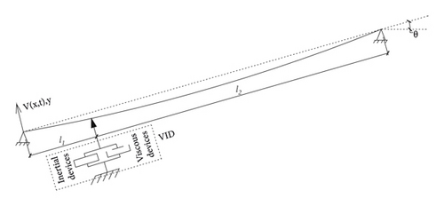
The following theoretical analysis model was established to study the damping effect of the VID on the cable.
4.1. In-Plane Vibration of a Shallow Cable with a VID
4.2. Normalized Wave Number of Symmetric Mode
4.3. Normalized Wave Number of Antisymmetric Mode
5. Cable-VID System Testing and Analysis
5.1. Experimental Setup of Scaled Cable-VID System
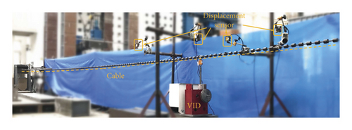
To experimentally evaluate the vibration control performance of the VID, determine the frequency variation characteristics of the cable-VID system, and validate the theoretical analysis results, prototype dampers with three different inertial coefficients and shallow cable were established in the laboratory. Considering the experimental conditions, this study chose a wire rope with a diameter of 9.3 mm as the cable, which was horizontally anchored to the reaction frame and increased the wire rope’s weight by installing a small mass block. Figure 5 shows the cable-VID system. The main parameters of the cable are listed in Table 3. Figure 6 illustrates a schematic diagram of the cable vibration control. The VID was attached to the cable 2.3 m away from the anchor, incorporating a load cell and a displacement sensor to monitor the mechanical performance of the VID. Six laser displacement sensors were installed 0.7 m, 1.4 m, 2.3 m, and 3.5 m away from the left anchor, and 1.4 m and 2.3 m away from the right anchor. Displacement sensors were adopted to identify the mode damping ratios of the cable. The DH5956 data acquisition system collected all the signals with a 1000 Hz sampling frequency.
| Item | Value |
|---|---|
| Cable force (N) | 7170 |
| Cable length (m) | 14 |
| Mass per unit length (kg/m) | 2.402 |
| Cross-sectional area (m2) | 5.02 E − 5 |
| Irvin parameters (λ2) | 3.316 |

5.2. Analysis of Vibration Control Effect
At present, analyzing the attenuation speed of the cable’s free vibration can help determine the damper’s influence on the vibration of the cable. The evaluation index is the mode damping ratio. It was found that the cable could be excited easily by just one human at the antinode of the vibration mode shape with the excitation frequency tuned to the natural cable frequency. When the vertical vibration amplitude reached a certain value, the man stopped excitation and allowed the cable to continue freely decaying the vibration. The time history of the decay of the vertical vibration was then recorded [15, 41, 42]. In this experiment, under the cable’s controlled vibration condition, the time history curve collected in the experiment was fitted by the exponential function. The free vertical vibration data were filtered by a bandpass filter to eliminate the influence of other modes.
At the same time, the parameters of the VID are normalized according to equation (24), the normalized parameters are brought into equations (30) and (33), and the mode damping ratios can be obtained through equation (35). The normalized values of each parameter are shown in Table 4.
| Cases 1 and 4 | Cases 2 and 5 | Cases 3 and 6 | Cases 1∼6 | ||
|---|---|---|---|---|---|
| Inertial coefficient, bd (kg) | 4.2334 | 10.0136 | 20.4042 | Viscous coefficient, cd (N·s/m) | 66.0079 |
| Normalized inertial coefficient, | 0.13 | 0.30 | 0.61 | Normalized viscous coefficient, | 0.16 |
The normalized inertial coefficients of case 1, case 2, and case 3 are 0.13, 0.3, and 0.61, respectively. The attenuation curves of the first symmetric mode vibration are shown in Figures 7(a)–7(c), respectively. The normalized inertial coefficients of case 4, case 5, and case 6 are 0.13, 0.3, and 0.61, respectively. The attenuation curves of the first antisymmetric mode vibration are shown in Figures 8(a)–8(c), respectively. By fitting the time history curve at the cable damper’s installation location, the damping ratios of the first symmetric and antisymmetric modes were obtained. Simultaneously, the symmetric point curve at the other end of the cable was obtained. By comparing the amplitude at damper’s installation location and its symmetric point at the other end of the cable, the displacement amplification effect of the cable-VID system can be observed.
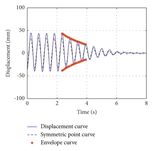
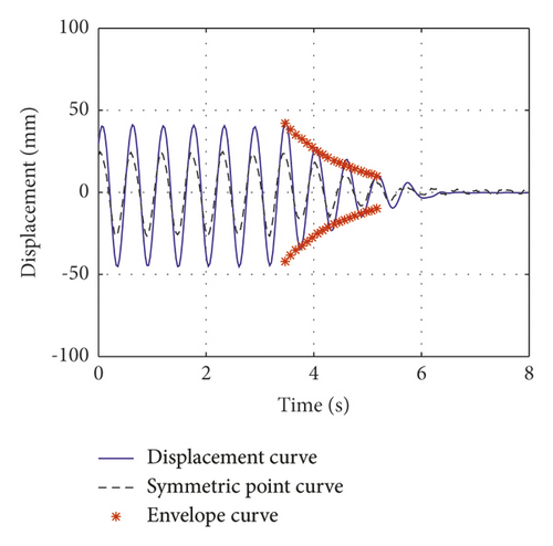
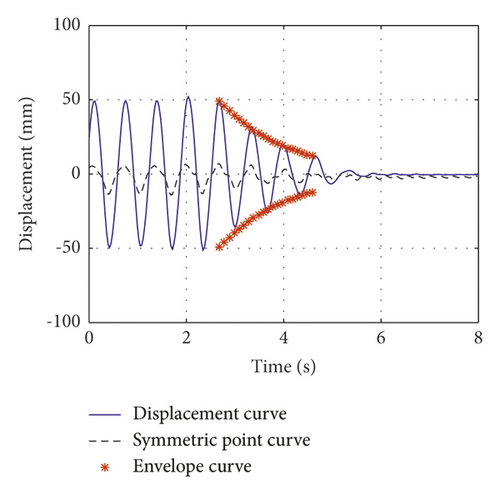
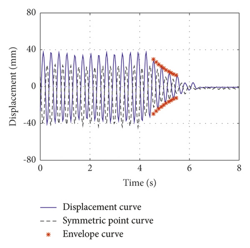
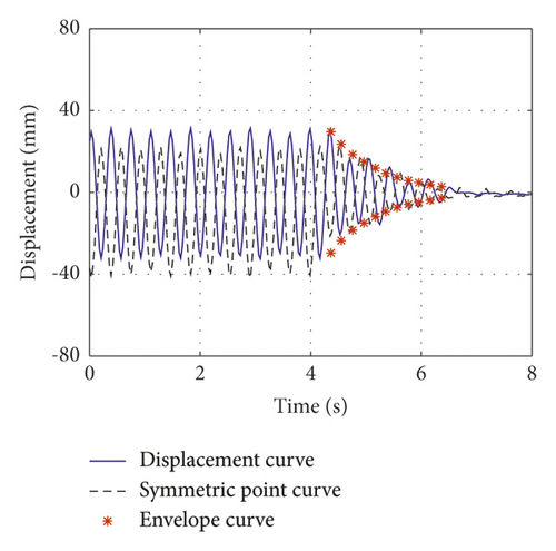
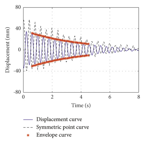
This study presents the measured damping ratio and the theoretically damping ratio at the damper’s installation location. Simultaneously, the normalized frequency calculated by the theory was deduced and compared with the measured frequency, which verified the accuracy of the theoretical calculation; it can also explain the change in the cable frequency with the additional VID. The test results, theoretical results, and deviations are summarized in Tables 5–7.
| First symmetric mode | First antisymmetric mode | |
|---|---|---|
| Test damping ratio, ξ1 (%) | 4.23 | 6.72 |
| Theoretical damping ratio, ξ2 (%) | 4.42 | 6.88 |
| Deviation, (ξ1 − ξ2)/ξ2 (%) | −4.30 | −2.32 |
| Test frequency, f1(Hz) | 1.92 | 3.17 |
| Deduced frequency, f2 (Hz) | 1.92 | 3.15 |
| Deviation, (f1 − f2)/f2 (%) | 0 | 0.63 |
| First symmetric mode | First antisymmetric mode | |
|---|---|---|
| Test damping ratio, ξ1 (%) | 6.38 | 6.24 |
| Theoretical damping ratio, ξ2 (%) | 6.17 | 6.17 |
| Deviation, (ξ1 − ξ2)/ξ2 (%) | 3.40 | 1.13 |
| Test frequency, f1 (Hz) | 1.77 | 2.77 |
| Deduced frequency, f2 (Hz) | 1.77 | 2.73 |
| Deviation, (f1 − f2)/f2 (%) | 0 | 1.47 |
| First symmetric mode | First antisymmetric mode | |
|---|---|---|
| Test damping ratio, ξ1 (%) | 7.51 | 2.02 |
| Theoretical damping ratio, ξ2 (%) | 7.51 | 2.17 |
| Deviation, (ξ1 − ξ2)/ξ2 (%) | 0.00 | −6.91 |
| Test frequency, f1 (Hz) | 1.55 | 2.59 |
| Deduced frequency, f2 (Hz) | 1.55 | 2.47 |
| Deviation, (f1 − f2)/f2 (%) | 0 | 4.85 |
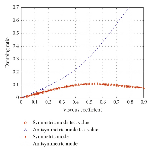
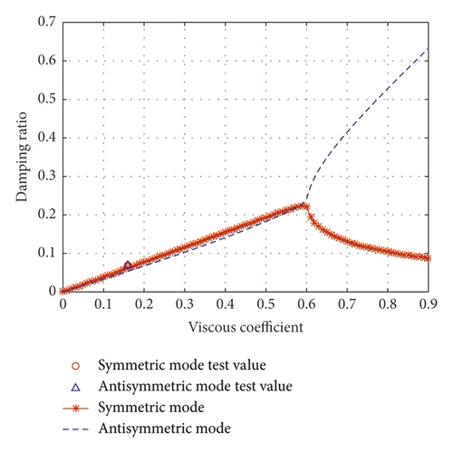
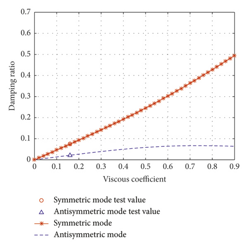
Figures 9(a)–9(c) show the comparison of theoretical results and experimental results for the different normalized inertial coefficients. The figure shows that the test results are in good agreement with the theoretical results. The theoretical analysis method described in this study is accurate, and the mode damping ratio of the cable can be analyzed by this theoretical method.
5.3. Optimal VID Design Method
This study uses an iterative method to solve equations (29) and (32). With the pure inertial device’s contribution, the viscous coefficient is zero. Adding inertial coefficient generally reduces normalized wave numbers. All wave numbers decrease with an increasing inertial coefficient. In general, higher modes are associated with faster decreasing rates than lower modes. Finally, the decreasing wave numbers approach asymptotic lower bounds. This situation is shown in Figure 10. These wave numbers should be used as the initial value of the iteration in the VID optimization calculation [30].
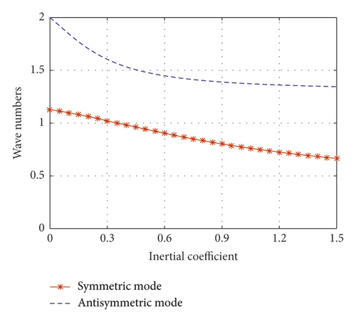
Figure 10 shows that, in both symmetric and antisymmetric modes, the lower limit of the frequency can be approximated as the adjacent lower mode of an uncontrolled cable with a length of l2 (equivalent to the cable being clamped in the damper installation location). The shallow cable’s theoretical results in this study are approximately the same as those previously reported in [30, 35].
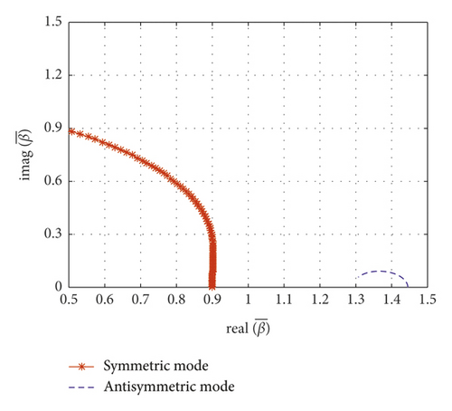
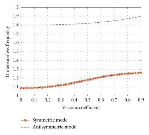
When the normalized inertial coefficient is 0.13, Figure 11(a) shows a clear schematic drawing of wave number loci. The wave number of the first symmetric mode moves toward the right with an increasing viscous coefficient. As the viscous coefficient approaches infinity (c = ∞), the first symmetric mode approaches the real axis. This finding implies that the cable is prone to the locking-like effect at the damper location. The first antisymmetric mode’s wave number moves along a quarter-circle with an increasing damping coefficient. In Figure 11(a), when the normalized viscous coefficient increases, the first antisymmetric mode’s wave number will reach the imaginary axis. The first antisymmetric mode is overdamped after the locus reaches an imaginary axis. This reveals the reason why the damping ratio of the antisymmetric mode increases with the increase of the viscous coefficient when the normalized inertial coefficient is 0.13 in Figure 9(a). As shown in Figure 11(d), when the viscous coefficient increases, the first symmetric mode frequency and the first antisymmetric mode frequency both increase.
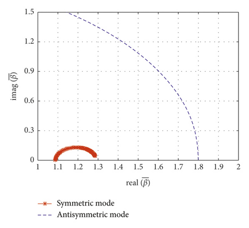
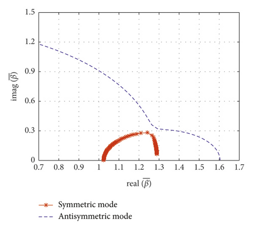
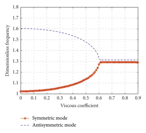
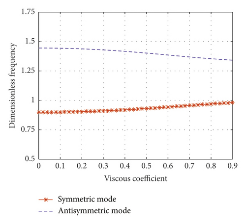
When the normalized inertial coefficient is 0.3, Figure 11(b) shows a schematic drawing of wave number loci. The wave number of the first symmetric mode moves toward the right with an increasing viscous coefficient. As the damping coefficient approaches infinity, the first symmetric mode approaches the real axis. The first antisymmetric mode’s wave number still moves along a nearly quarter-circle with increasing viscous coefficient when approaching the imaginary axis. As shown in Figure 11(b), the wave numbers of the symmetric mode and the antisymmetric mode have an intersection point at a certain viscous coefficient (). Also shown in Figure 9(b), before reaching this certain normalized viscous coefficient, the damping ratios of the first symmetric mode and the first antisymmetric mode of the cable are almost the same. However, after exceeding this certain viscous coefficient, the damping ratio of the first symmetric mode decreases, and the damping ratio of the first antisymmetric mode continues to increase. This study defines this viscous coefficient () and the corresponding inertial coefficient () as optimal value. Because, after exceeding this value, the damping ratio of the symmetric mode will gradually decrease, this value can obtain optimal damping ratio of the two adjacent vibration modes. As shown in Figure 11(e), as the viscous coefficient increases, the first symmetric mode’s frequency and the first antisymmetric mode’s frequency tend to be consistent.
Figure 11(c) shows a schematic drawing of the wave number loci when the normalized inertial coefficient is 0.61. The first symmetric mode’s frequency moves along a quarter-circle with an increasing viscous coefficient. The first symmetric mode is overdamped after the locus reaches an imaginary axis. The wave number of the first antisymmetric mode moves toward the left with an increasing viscous coefficient. As the damping coefficient increases in Figure 11(c), the first symmetric mode approaches the imaginary axis. This reveals the reason why the damping ratio of the symmetric mode increases with the increase of the viscous coefficient when the normalized inertial coefficient is 0.61 in Figure 9(c). As shown in Figure 11(f), the symmetric mode frequency and the antisymmetric mode frequency get close to each other, but they do not converge.
5.4. Mode Shape Analysis
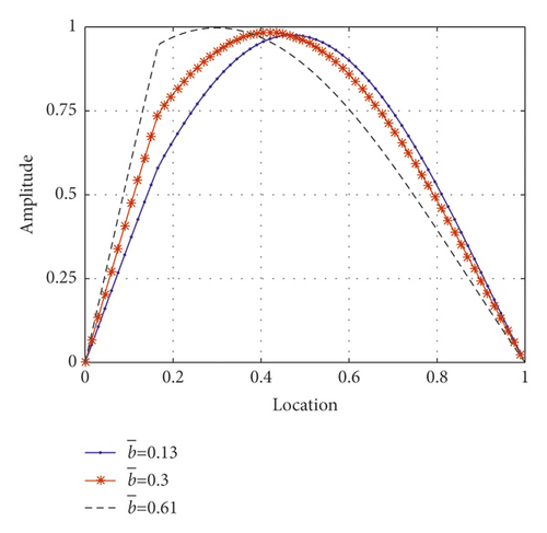
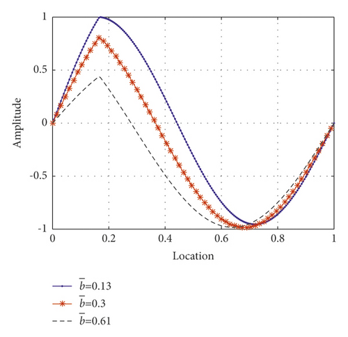
Figures 12(a) and 12(b) show the normalized mode shapes of the first symmetric mode and first antisymmetric mode of the cable under different inertial coefficients, respectively. The figure accurately explains the displacement amplification observed in the experiment. For the symmetric mode, after the inertial coefficient is optimized (), the VID can increase the displacement of the cable at the installation location of the damper and consumes more energy. The vibration can be quickly attenuated. The effect of the VID on the displacement amplification of the damper can be intuitively understood as improving the installation location of the damper. For the first symmetric mode, the larger the normalized inertial coefficient, the better the damping effect. However, for the first antisymmetric mode, the amplification phenomenon can also be understood as improving the damper’s installation location. However, when the inertial coefficient exceeds the optimal value (), it is equivalent to the fact that VID has been installed near the node of the antisymmetric mode shape. The mode damping will be reduced due to the excessive inertial coefficient.
6. Conclusions
- (1)
The novel viscous inertial damper constructed in this study can effectively suppress cable vibration, improve the cable’s mode damping ratio, and more quickly attenuate cable vibration.
- (2)
Compared with the traditional complex-valued modes analysis, after the parameters are normalized according to the method described in this article, the frequency-dependent phenomena and the damping ratio of the symmetric and antisymmetric modes of the cable were discussed in detail.
- (3)
When the normalized inertial coefficient and the normalized viscous coefficient are optimal, the optimal damping ratio of the two adjacent vibration modes is obtained simultaneously. For example, the first symmetric mode and the first antisymmetric mode are optimal at the same time, or the first antisymmetric mode and the second symmetric mode are optimal at the same time. However, the frequencies of the two modes are the same.
- (4)
According to the numerical method and the test method proposed in this study, the parameters of the damper can be designed according to the target mode of vibration. After theoretical calculations, the method proposed in this study can be used to precisely obtain the viscous and inertial coefficients.
- (5)
In the symmetric and antisymmetric modes, the displacement amplification phenomena of the VID were verified by theoretical analysis and experimental observation. This finding proves that the VID provides superior vibration reduction performance when the inertial coefficient is optimal. The VID fabricated in this study can overcome the disadvantages of displacement loss caused by the traditional oil damper.
Conflicts of Interest
The authors declare that there are no conflicts of interest regarding the publication of this paper.
Acknowledgments
This research was funded by the National Science Foundation of China (Grant number 51978236). The authors are grateful for the support.
Open Research
Data Availability
All the data generated or analyzed during this study are included within this article.


