Harmonic Current Suppression of Dual Three-Phase PMSM Based on Model Predictive Direct Torque Control
Abstract
The traditional direct torque control (DTC) method will produce a larger harmonic current in the x, y subspace when applied to a dual three-phase permanent magnet synchronous machine (DTP-PMSM) because the voltage vector used for DTC is not equal to zero in the x, y harmonic subspace. To mitigate this problem, in this manuscript, a model predictive direct torque control (MPDTC) method is proposed to eliminate the harmonic current in DTP-PMSM. The spatial distribution characteristic DTP-PMSM voltage vector is analyzed; then, the table of vector group can be obtained according to DTC, and each vector group can be combined to obtain the zero-voltage vector in the x, y subspace. According to the cost function, MPDTC selects the vector group and obtains the optimal vector sequence combination to eliminate the harmonic current in the x, y subspace. Furthermore, the MPDTC achieves closed-loop control of harmonic currents in the x, y subspace. The MPDTC can also eliminate harmonic currents caused by other factors. The simulation results show that the method of MPDTC can effectively suppress the harmonic current of DTP-PMSM.
1. Introduction
The multiphase motor reliability is high and valuable for small torque ripples [1], which makes it suitable for electric vehicle [2], wind power generation [3], ship propulsion [4], and also for electric aircraft [5].
DTP-PMSM is an asymmetric six-phase motor with two sets of three-phase winding with a shift of 30 degrees. In this motor, the voltage vector in α, β subspace is projected to the x, y harmonic subspace, which generated the harmonic current in the x, y subspace. When using a voltage vector to control a dual three-phase motor, it is necessary to eliminate its influence on the x, y harmonic subspace. Therefore, the conventional vector control and direct torque control methods of three-phase PMSM are unsuitable for DTP-PMSM [6].
To eliminate the current harmonics of the DTP-PMSM, the four-vector space vector pulse width modulation (SVPWM) method is proposed in [6, 7]. The four vectors of the α, β subspace are used to synthesize the desired vectors, which can minimize the amplitude of synthesis vector of the x, y subspace and thus achieve the minimum harmonic current of the x, y subspace [8, 9]. Adopt two-zero sequence injection PWM and three-phase decoupling methods to reduce the harmonic current in the x, y subspace, respectively. To apply DTC in DTP-PMSM and effectively eliminate the harmonic current in x, y subspace, the dual zero sequence injection PWM method is used to DTC [10]. The four-vector SVPWM method can also be applied to DTC to reduce the DTP-PMSM harmonic current [11]. All of these harmonic current elimination methods for DTP-PMSM have a vector pulse width readjustment process, which is complicated to implement.
Model predictive control (MPC) has the advantages of being easy to achieve [12], multiobjective control [13], and suitable for nonlinear systems. Recently, with the wide application of MPC in motor control [14], many scholars have already discussed it in multiphase motors [15–18]. Zhang et al. [15] combine four-vector SVPWM with MPC for harmonic current suppression to achieve better dynamic performance and robustness when motor parameters change. According to the distribution characteristics of the four amplitude vectors of DTP-PMSM, a virtual vector with a zero amplitude in the x, y subspace is synthesized in advance to perform MPC to suppress harmonic currents [16–18]. The virtual vector MPC (VV-MPC) method proposed in [16] uses the largest and the second amplitude vector of α, β subspace to synthesize 12 virtual vectors with a zero amplitude in the x, y subspace. Then, these 12 virtual vectors are applied to MPC. Based on [16, 17], MPC is used to select two virtual vectors and their action time from 12 virtual vectors for synthesis. Luo and Liu [18] use 36 vectors to synthesize 24 virtual vectors with zero amplitude in the x, y subspace, and then combine the deadbeat method and MPC to control the system.
In actual systems, due to asymmetry and dead-time effects, the harmonic currents in the x, y subspace still exist [16, 19], even the amplitude of virtual vectors in the x, y subspace is zero. At this time, since the amplitude of the virtual vector in the x, y subspace is zero, it cannot be adjusted to reduce the actual harmonic current in the x, y subspace. In addition, the cost function does not include the harmonic currents of x, y subspace in [16–18]. Therefore, the closed-loop adjustment of the harmonic current cannot be realized.
-
A new method of MPDTC combining DTC and MPC is proposed. The proposed method uses the vector table of DTC to reduce the number of prediction vectors from 12 to 3, which reduces the computational workload of MPC.
-
The cost function proposed only contains the harmonic current, which not only simplifies the cost function of MPC but also realizes the closed-loop control of the harmonic current.
-
The proposed method replaces the virtual vector synthesis commonly used in multiphase motors with the dynamic combination of voltage vectors in sequential and reduces the system’s complexity.
-
The proposed method is compared with DTC and VV-MPC using simulation software, and the output results verify the feasibility and effectiveness of the proposed method.
2. Model of DTP-PMSM
The structure of neutral point isolation DTP-PMSM and its driver system studied in this paper are shown in Figure 1.

When the two neutral points of the system are isolated, there is no current in the o1 and o2 subspaces, so it is not considered in this article.
Among them, α, β subspace is the subspace of motor energy conversion, including the fundamental wave and k = 12m ± 1 (m = 1,2,3, …) harmonics. The x, y subspace contains k = 6m ± 1(m = 1,3,5, …) harmonics, and the o1, o2 subspace contains k = 3 m (m = 1,3,5, …) harmonics. Since the two neutral points of the system are isolated, there is no current in the o1, o2 subspace, so it is not considered in this article.
3. Vector Selection Based on DTC
- (1)
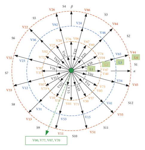
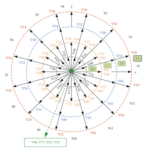
The L4 and L1 vector in the α, β subspace corresponds to the L1 and L4 vector in the x, y subspace, respectively. These harmonic current elimination methods for DTP-PMSM have a vector pulse width readjustment process, which is complicated to implement.
- (2)
The amplitude of the L3 and L2 vectors in the α, β and x, y subspaces are the same
- (3)
The position of the same vector in the two subspaces is changed
- (4)
The vectors’ direction of L3, L4, and L1 is the same in the α, β subspace, and the vectors’ direction between L3, L4, and L1 is exactly opposite in the x, y subspace
From characteristics (1) and (3), it can be seen that the L4 vector with the largest amplitude in the α, β subspace corresponds to the L1 vector with the smallest amplitude in the x, y subspace, and the corresponding vector position changes. From formula (5), it can be seen that when k = 1, α, β subspace is obtained and, when k = 5, x, y subspace is obtained. From this, the following conclusion can be drawn.
In the α, β subspace, two adjacent L4 vectors are with a difference of △θ = π/6 angle, and the angle difference corresponding to the L1 vector on the x, y subspace should be k × △θ = 5×π/6 = 5π/6.
The above conclusion is consistent with the vector positions in Figure 2, so the three largest L4 vectors V1, V2, and V3 that are arbitrarily continuous in the α, β subspace, which correspond to the smallest L1 vectors in the x, y subspace, have the following spatial position relationships, as shown in Figure 3.
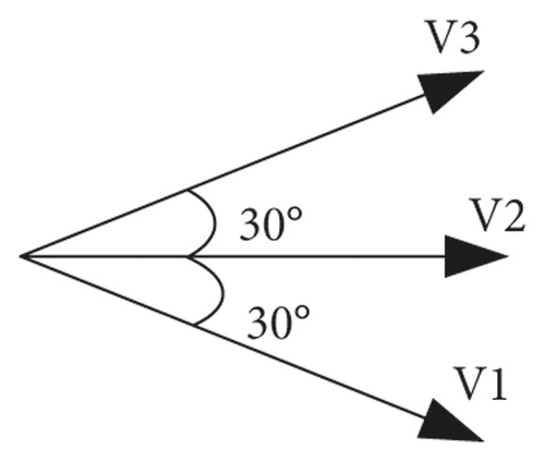
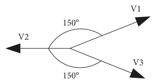
According to the principle of volt-second balance, the combination of these three maximum amplitude voltage vectors can make the volt-second voltage amplitude in the x, y subspace zero or a specified value. To achieve the closed-loop adjustment of the actual harmonic currents, it is necessary to combine the three continuous vectors in real time according to the actual harmonic currents to achieve the voltage required to eliminate the harmonic currents at the volt-second balance level.
According to the above analysis, combined with the rule of the DTC vector table, the largest 12 vectors can be divided into 4 groups, and each group includes 3 adjacent vectors whose angles differ by 30 degrees. Taking the motor stator flux linkage in sector S1 as an example, DTC vector (Table 1) can be obtained according to Figure 2(a).
| ∆Ψ | ∆Te | Vector |
|---|---|---|
| 1 | 1 | V44, V54, V66 |
| 0 | V0 | |
| −1 | V51, V55, V45 | |
| −1 | 1 | V26, V22, V32 |
| 0 | V0 | |
| −1 | V33, V13, V11 | |
In Table 1, 1 means need to increase, −1 means need to decrease, and 0 means need to maintain. When the motor rotates counterclockwise to sectors S2, S3, S4⋯S12, each vector in Table 1 also rotates counterclockwise according to the position in Figure 2(a). The selection of the zero vector follows the principle of minimum switching times.
4. The Proposed MPDTC
When implementing DTC on DTP-PMSM, according to Table 1, three vectors can be obtained at each step. To realize the real-time combination of these three vectors and the closed-loop control of harmonic currents, the MPC needs to be combined.
It can be seen that the cost function in (14) does not require adjustment factors and is simple and easy to implement.
On the basis of the above analysis, the system block diagram of the proposed MPDTC method is shown in Figure 4.
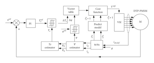
This control system is different from the general MPTC [12]. Firstly, according to the DTC rules, based on the feedback flux and torque errors, a group of three vectors is obtained from the DTC vector (Table 1). Secondly, according to the feedback harmonic current ix, iy, the cost function of formula (14) is used for prediction, and the optimal vector Vopt is selected from the group. Finally, the group of three vectors will be repeatedly selected in multiple prediction cycles, which are equivalent to the dynamic combination of the three vectors according to the real-time feedback ix, iy and realize the closed-loop control of ix, iy.
Compared with VV-MPC, MPDTC uses a dynamic combination of vectors instead of vector synthesis. Moreover, VV-MPC needs to select the optimal vector from the 12 vectors each time. In comparison, MPDTC only needs to select the optimal vector from 3 vectors, which greatly reduces the computational workload.
5. Simulation Research
In order to verify the effectiveness of the method proposed in this paper, Matlab/Simulink software is used for results’ verification. The parameters of DTP-PMSM used in the simulation are shown in Table 2 [22]. The speed is set to 3000 rpm. The DC link is set to 600 V. The sampling and control cycle is set to 10−5s. The initial torque of the motor is set to 3 N·m and a step change load of 16 N·m is given at t = 0.05 s.
| Machine parameter | Value |
|---|---|
| Rated power | 5 kW |
| Rated speed | 3000 rpm |
| Rated torque | 16 N.m |
| Pole pairs | 5 |
| Ld, Lq | 2.4633 mH, 2.4733 mH |
| Leakage inductance | 1.520747 mH |
| Resistance | 0.0495 Ω |
| Flux | 0.0492 Wb |
| Inertia(J) | 0.0015 kg m2 |
| Viscous damping(F) | 0 N·ms |
To verify the steady-state and dynamic performance of the proposed MPDTC method, it is compared with the traditional DTC and the VV-MPC proposed in [16]. The steady-state and dynamic performance simulation results of the three methods are shown in Figure 5.
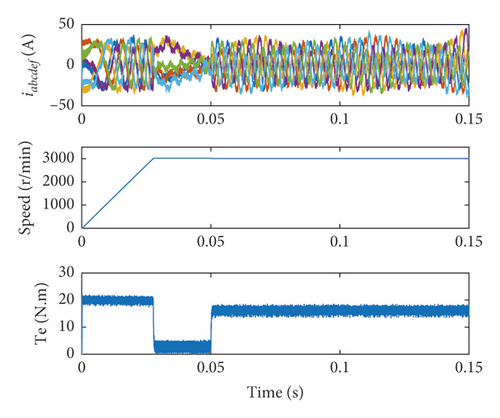
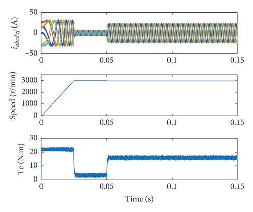
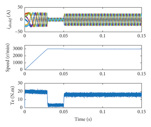
From the speed and torque simulation results in Figure 5, the proposed MPDTC method has the same fast torque and speed dynamic response performance as the other two methods. From the perspective of the six-phase current iabcdef, the six-phase current of DTC is relatively messy in dynamic and steady-state processes. The proposed MPDTC method can always keep iabcdef smooth and symmetrical in a dynamic and steady-state like VV-MPC. Since the complicated process of virtual vector synthesis makes virtual voltage vector more accurate in VV-MPC, the torque ripple in Figure 5(b) is smaller than the proposed MPDTC in Figure 5(c). However, the proposed MPDTC method has no vector synthesis process, and it is simple and easy to implement with less computational workload.
Because the smoothness and symmetry of the six-phase current are affected by the harmonic current components, it is necessary to further analyze the harmonic current simulation results, as shown in Figure 6.
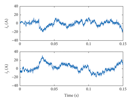
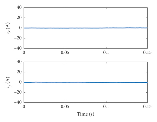
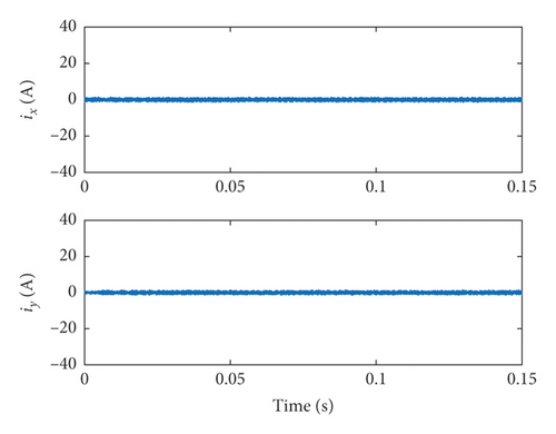
It can be seen from Figure 6 that when traditional DTC is applied to DTP-PMSM, its harmonic currents ix, iy are larger, while VV-MPC and MPDTC can effectively suppress harmonic currents. The comparison of the ix and iy harmonic currents of the three methods is shown in Table 3.
| Method | Average ix (A) | Average iy (A) |
|---|---|---|
| DTC | 4.1386 | 6.4443 |
| VV-MPC | 0.21 | 0.20 |
| MPDTC | 0.47 | 0.46 |
Table 3 illustrates that the proposed MPDTC method can effectively suppress the harmonic currents in DTP-PMSM. Because of the accurate virtual voltage vector synthesized by VV-MPC, the ix,iy of VV-MPC is smaller than that of MPDTC in Table 3. If the real-time vector combination of MPDTC needs to be more accurate and precise, a higher control frequency is need for vector prediction and combination.
In actual systems, harmonic currents ixand iy will be generated due to system asymmetry and dead time. In order to verify MPDTC’s ability to suppress these harmonic currents produced by the systems, the following simulation adds interference harmonic currents on ix, iy. It can be seen from [19] that the main harmonic currents is the 5th harmonics to the fundamental component due to dead time. In the following simulation, the 5th (1250 Hz) harmonic current of 250 Hz fundamental component is added to ix, iy with an amplitude of 5A. In order to achieve better simulation results, the sampling and control cycle is set to 10−6s.The simulation result is shown in Figure 7.
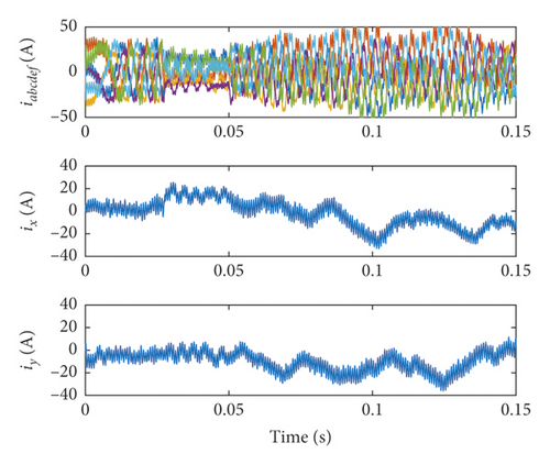
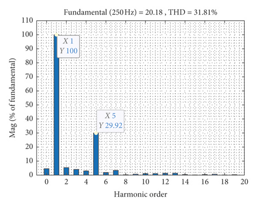
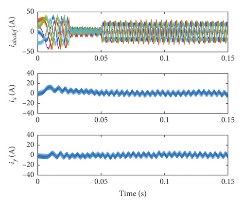
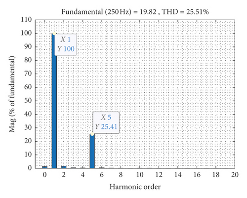
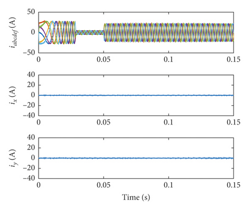

From Figure 7, it can be seen that DTC and VV-MPC cannot effectively suppress the added 5th harmonic current, but the MPDTC can effectively suppress the added 5th harmonic current. The numeric of ix,iy and THD of the three methods are shown in Table 4.
| Method | Average ix (A) | Average iy (A) | Total THD (%) | 5th THD (%) |
|---|---|---|---|---|
| DTC | 4.2178 | 5.3135 | 31.81 | 29.92 |
| VV-MPC | 4.0354 | 3.4171 | 25.51 | 25.41 |
| MPDTC | 0.2066 | 0.2509 | 3.84 | 1.919 |
The results in Table 4 shows that the MPDTC method is superior to DTC and VV-MPC in suppressing the added 5th harmonic current, since MPDTC realizes the closed-loop control of ix,iy by using the dynamic combination of voltage vectors. At the same time, since the sampling and control period is set to 10−6s, the dynamic voltage vector combination during MPDTC control is more accurate, and the average values of ix and iy in Table 4 are less than those in Table 3.
6. Conclusion
The MPDTC proposed in this paper can make full use of the advantages of DTC and MPC to control DTP-PMSM. The method not only has the fast dynamic response performance of DTC but also reduces the number of prediction vectors of MPC and the computational workload of MPC.The method does not contain complex vector synthesis process, but can effectively suppress the harmonic current of dynamic and steady state. Based on the simplified cost function, it realizes the closed-loop control for harmonic current which can suppress the interference harmonic current. From simulation results, it is proved that the proposed method has an advantage over VV-MPC and DTC in DTP-PMSM.
Conflicts of Interest
The authors have no conflicts of interest regarding the publication of this study.
Acknowledgments
The authors thankfully acknowledge the support of Taizhou University and Dr. Dan Sun from Zhejiang University for their assistance to carry out this study. This work was supported in part by the Youth Fund of Zhejiang Provincial Natural Science Foundation (Grant no. LQ21F030002) and the Jiangsu Provincial Postdoctoral Science Foundation (Grant no. 2020Z230).
Open Research
Data Availability
All data, together with relevant analysis scripts and files, are available from the corresponding author upon request.


