Deflection Calculation Based on SDOF Method for Axially Loaded Concrete-Filled Steel Tubular Members Subjected to Lateral Impact
Abstract
Axial force has a great influence on the dynamic behavior and the impact resistance of concrete-filled steel tubular (CFST) members. Based on numerical simulation and theoretical analysis, the impact response and deflection calculation method for axially loaded CFST members subjected to lateral impact are investigated in this paper. The nonlinear numerical model of an axially loaded CFST member considering the strain rate effects has been established, and the simulation accuracy has been validated by comparing with existing test results. The contrastive investigation is carried out to illustrate the influence of axial load on the variation pattern of impact force for CFST members under various structural and impact parameters, and its result indicates that the impact force-time histories for CFST members with different axial loads are mainly characterized by rectangular pulse and triangular pulse. Moreover, a simplified calculation method considering the effect of axial force is proposed based on the equivalent single degree of freedom (SDOF) method, devoted to predicting the deflection of axially loaded CFST members subjected to lateral impact. The comparisons with the numerical simulation prove that the deflection calculation method has a reasonable accuracy; thus, the proposed method can be utilized in the damage assessment and anti-impact design for CFST members subjected to lateral impact and axial load.
1. Introduction
Concrete-filled steel tubular (CFST) members exhibit mechanical benefits of high strength and favorable ductility; hence, they have been widely applied to high-rise and long-span engineering structures [1–3]. During the whole service life cycle, CFST members may inevitably suffer from various impact accidents caused by vehicles, vessels, and trains [4]. Meanwhile, CFST members will always bear the axial load induced by superstructure during the whole impact process. Therefore, in order to well reflect the actual impact situations, it is of realistic significance to further investigate the impact response and deflection calculation method for axially loaded CFST members subjected to lateral impact.
Some researchers have carried out impact tests and simulation analysis on the dynamic response of CFST members under lateral impact [5–9], including a small number of investigations considering the effect of axial force on the mechanical behavior for CFST members. Wang et al. [10] conducted a series of drop weight tests on CFST members with the fixed-sliding boundary conditions. The results showed that the impact force and residual deflection of CFST members varied greatly with the axial load. Due to the increase of the axial load, the duration of impact force would decrease gradually and the impact force would show a more obvious unloading trend. The residual deflection of CFST members changed considerably with the application of axial load, while there was no clear regularity in its variation. In addition, it can be obtained from the tests of Yousuf et al. [11] that the axial force had a weakening effect on the impact strength of CFST members. Aghdamy et al. [12] carried out a parametric sensitivity analysis of CFST members subjected to lateral impact through numerical simulation. It was found that the eigenvalues of impact force, such as initial peak force, residual impact force, and impact duration, decreased slightly with the increase of the axial load. Correspondingly, the deflection of CFST members only increased by a small amplitude. Yang et al. [13] conducted the drop weight impact tests on recycled aggregate CFST members, including the investigation related to the influence of axial load on the dynamic response for CFST members. From the test results, it can be seen that the local buckling appeared at the midspan and the supports of CFST members. With the increase of the axial load ratio, the local buckling phenomenon became more and more serious and the residual deflection of CFST members increased substantially. Aghdamy et al. [14–16] performed a series of impact tests and numerical simulations on concrete-filled double-skin tube (CFDST) members. It was indicated that the increase of axial load was more likely to cause global buckling for CFDST members, which resulted in a greater increase in the maximum and residual deflection of CFDST members. From the above investigations, it can be concluded that there is still no clear conclusion about the influence of axial load on the deflection and impact force for CFST members under lateral impact.
Some investigations have studied the simplification of impact force for different structural members. For the structural members with high impact resistance, the impact energy was absorbed mainly by the global deformation during the impact process. Accordingly, the impact force, which experienced a stable platform stage and maintained for a long period of time after the short peak period, could be reasonably simplified into rectangular pulse [17, 18]. If the impact resistance of structural members was too poor to fully withstand impact energy, the structural members would be damaged locally in a relatively short period of time, and the impact force would be unloaded directly after the peak stage. Consequently, some investigations simplified the impact force into pulse loads such as isosceles and right triangular pulses according to its characteristics [19–23]. However, there is still a lack of research on the variation pattern and equivalence principle of impact force for CFST members considering the effect of axial force, which needs to be further investigated.
The equivalent single degree of freedom (SDOF) method idealizes the actual impact system as a mass-spring model with an equivalent lumped mass, equivalent stiffness, and equivalent impact load. The deflection of actual members is obtained by solving the dynamic differential equation of the equivalent SDOF model [24]. The classical equivalent SDOF method mainly reflects the bending performance of structural members, while without considering the effect of axial force on the calculation method [25, 26]. In order to obtain a more accurate calculation model, some researchers have improved the classical equivalent SDOF method [27–30]. Zhang et al. [31] established an equivalent SDOF model considering the interaction of axial load-bending moment for CFST columns subjected to blast load. This method considered the combined action of axial force and blast load in the process of calculating the ultimate bending strength. Nassr et al. [32] investigated the effect of axial load on the strength and stability of steel columns under blast load based on the equivalent SDOF method. The additional lateral force caused by the second-order effect of the axial load was added to the equivalent impact load in the SDOF differential equation. For axially loaded CFST members subjected to lateral impact, it is recognized that the axial force will generate the geometric stiffness, which will change the joint stiffness of the equivalent SDOF model and affect the calculation results of deflection. Therefore, a more reasonable and feasible way is to modify the differential equation and resistance function of the equivalent SDOF model to reflect the effect of axial force on CFST members subjected to lateral impact.
To address these issues described above, the impact response and deflection calculation method for axially loaded CFST members subjected to lateral impact are investigated in this paper. The finite element analysis model of an axially loaded CFST member considering the strain rate effects and dynamic relaxation is established, and the accuracy of numerical simulation is validated by comparing with existing test results. The contrastive investigation of impact response for axially loaded CFST members with various structural and impact parameters is conducted based on numerical simulation, dedicated to illustrating the effect of axial load on the variation pattern of impact force. On this basis, the impact loads are simplified into pulse loads according to the types of impact force-time histories for CFST members. Moreover, a deflection calculation method of CFST members under lateral impact is established based on the equivalent SDOF method, and it reflects the effect of axial force by modifying the differential equation and the resistance function of the equivalent SDOF model. The general calculation flow of the proposed method is summarized for obtaining the deflection of axially loaded CFST members subjected to lateral impact, and the simulation results are utilized to validate and analyze the accuracy of the deflection calculation method.
2. Development of FEA Model and Experimental Validation
2.1. Finite Element Analysis Model
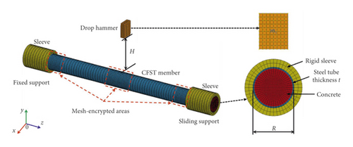
Figure 1 shows the finite element analysis model of CFST member subjected to lateral impact. The steel tube, core concrete, and drop hammer are simulated employing eight-node solid elements with reduced integration. In order to improve the accuracy and efficiency of the simulation, the mesh is encrypted at the impact position and the support areas [33]. The drop hammer is modeled as a rigid cuboid, and its initial velocity is given by the keyword INITIAL_VELOCITY_GENERATION. By limiting the displacement and rotation in other directions, the drop hammer moves only in the vertical direction. The supports are simplified into two hollow cylindrical sleeves. In order to achieve the experimental boundary conditions (fixed-sliding), the one sleeve fixes all the degrees of freedom, and the other sleeve fixes all the degrees of freedom except z direction (axial direction). Slip between the steel and concrete was not observed in the drop weight tests, and hence, the contact surfaces of the steel and concrete share common nodes. The keyword CONTACT_AUTOMATIC_SURFACE_TO_SURFACE is set to simulate the contact between the drop hammer, rigid sleeves, and the CFST member. The commercial finite element program LS-DYNA [34] is used to simulate the impact response of CFST members. The dynamic relaxation function of the implicit solver is utilized to initialize the stress caused by axial load, and then, the dynamic process of CFST members under lateral impact is simulated by explicit solver while the axial load is constant.
2.2. Introduction to Experimental Tests
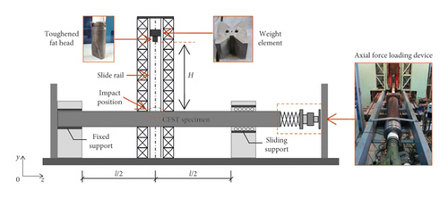
In [10], the authors carried out a series of drop weight tests on CFST members through a DHR9401 drop hammer test machine, as shown in Figure 2. The support restraint device provided the boundary constraints for the CFST member, and the loading device of the axial force applied the axial pressure for the CFST member. The weight of the drop hammer mc was 229.8 kg, and the different impact energy was obtained by changing the impact height (H). During the tests, the CFST member was first placed on the drop hammer test machine and the boundary condition was set as the fixed sliding, and then the axial load was applied at the sliding end of the CFST member. When the drop hammer was released from the design height, it would fall freely along the slipway and impact the CFST member in the midspan area. Six typical CFST members were selected from Ref. [10] to validate the accuracy of numerical simulation. Table 1 shows the detailed information of each CFST member, where l is the length of CFST member, R is the outer sectional diameter, t is the thickness of steel tube, fy is the average yield strength of steel, Es is the elastic modulus of steel, fcu is the average cube strength of concrete, μ = N/Nsc is the axial load ratio (where N and Nsc represent the axial load and axial bearing capacity of the CFST member, respectively), and v0 is the initial impact velocity.
| Number | l (mm) | R (mm) | t (mm) | fy (MPa) | Es (MPa) | fcu (MPa) | μ | v0 (m/s) |
|---|---|---|---|---|---|---|---|---|
| DBF14 | 1200 | 114 | 1.7 | 232.0 | 1.92 × 10⁵ | 48.7 | 0 | 3.9 |
| DBF13 | 1200 | 114 | 1.7 | 232.0 | 1.92 × 10⁵ | 48.7 | 0 | 4.8 |
| DBF19 | 1200 | 114 | 1.7 | 232.0 | 1.92 × 10⁵ | 48.7 | 0.3 | 4.8 |
| DZF22 | 1200 | 114 | 3.5 | 298.0 | 2.01 × 10⁵ | 48.7 | 0 | 7.6 |
| DZF26 | 1200 | 114 | 3.5 | 298.0 | 2.01 × 10⁵ | 48.7 | 0 | 11.7 |
| DZF31 | 1200 | 114 | 3.5 | 298.0 | 2.01 × 10⁵ | 48.7 | 0.3 | 11.7 |
2.3. Comparison of Simulation and Test Results
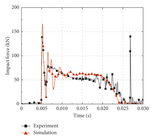
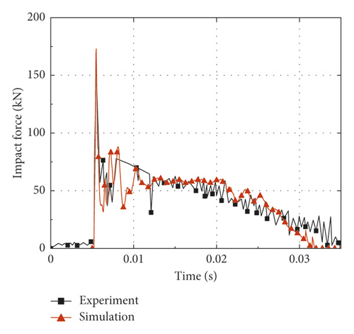
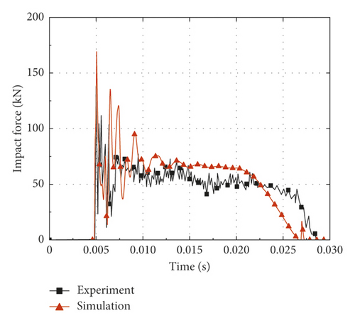
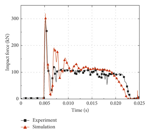
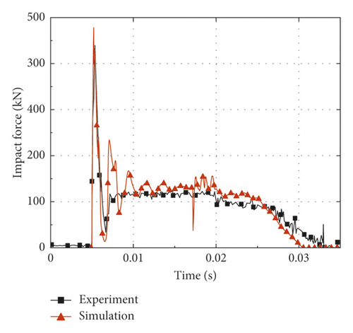
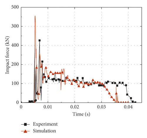
In order to validate the accuracy of numerical simulation, six typical CFST members described in Section 2.2 are calculated based on the finite element analysis method established in Section 2.1, and the comparisons are made between the simulation and test results. Figure 3 shows the predicted and measured impact force-time histories. It is noticed that the impact force reaches the maximum value (peak value) in a short time after the impact process begins. Then, the impact force maintains at the stability stage (platform value) for a long time after several short oscillations; meanwhile, the CFST member enters the global response stage. Finally, the impact force is gradually unloaded to zero. The comparisons between the simulation and test results are summarized in Table 2, where Fstab is the platform value of impact force, td is the duration of impact force, and δr is the residual deflection. It can be concluded from Table 2 that the average ratios of the simulation results to the test results for Fstab, td, and δr are 1.02, 0.91, and 0.97, respectively. By comparison, the platform value of impact force obtained by simulation is slightly higher than that of the test result, while the duration of impact force shows the opposite situation. Several factors may account for such discrepancies as follows: the support condition as well as the impactor of the actual impact test is not rigid enough, the energy dissipation caused by heat generation is ignored in numerical simulation, and the limitations for the material model of steel and concrete in numerical simulation. For all that, the predicted and measured residual deflections at the midspan of CFST members are roughly equal, which is mainly due to the fact that the total impulses of the simulations and tests are almost equal in the whole impact process.
| Number | Fstab, tested (kN) | Fstab, FEA (kN) | td, tested (ms) | td, FEA (ms) | δr, tested (mm) | δr, FEA (mm) |
|---|---|---|---|---|---|---|
| DBF14 | 59.5 | 61.2 | 19.3 | 19.0 | 19.44 | 18.90 |
| DBF13 | 60.8 | 62.1 | 30.0 | 26.7 | 41.88 | 39.20 |
| DBF19 | 62.7 | 65.9 | 24.8 | 21.9 | 25.30 | 24.80 |
| DZF22 | 112.8 | 113.6 | 18.2 | 17.8 | 39.42 | 38.50 |
| DZF26 | 123.2 | 125.3 | 27.0 | 25.5 | 87.20 | 83.70 |
| DZF31 | 125.7 | 121.1 | 38.2 | 30.7 | 101.70 | 98.70 |
Generally, it can be concluded that the results of the numerical simulation are in good agreement with the test results, regardless of the impact force-time histories or deformation modes. Obviously, the accuracy and reliability of the numerical simulation mentioned above can be validated. In addition, it is found that the axial force has a great influence on the impact response of CFST members during the simulation process. Hence, the following sections of this paper will investigate the effect of axial force on impact response through numerical simulation, and then, a deflection calculation method for axially loaded CFST members subjected to lateral impact is established by combining theoretical analysis and numerical simulation.
3. Influence of Axial Force on Impact Response for CFST Members
3.1. Variation Pattern of Impact Force
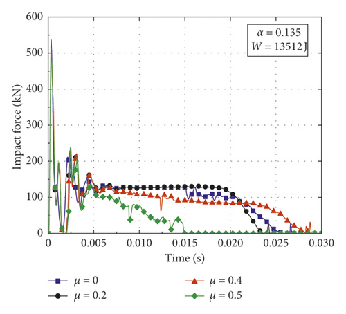
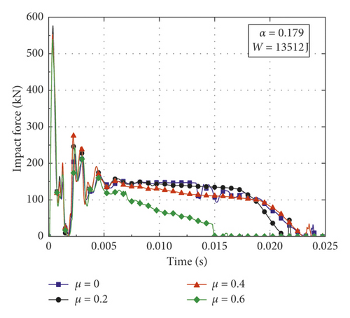
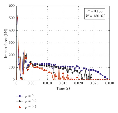
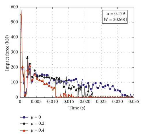
In order to investigate the influence of axial force on the variation pattern of impact force for CFST members with various structural and impact parameters, a contrastive investigation is conducted utilizing the numerical simulation. In this paper, the parameters varied in the numerical simulation including axial load ratio μ, impact energy , and steel ratio α = As/Ac (where As and Ac are the cross-sectional areas of steel tube and core concrete, respectively). The weight of the drop hammer, the boundary conditions, the outer sectional diameter, and the lengths of the CFST members are determined according to Section 2.2. The thicknesses of steel tubes are set as 3.5 mm and 4.5 mm, and the corresponding steel ratios are 0.135 and 0.179, respectively. The compressive strength of concrete is set as 33.4 MPa, and the yield strength and the elastic modulus of steel are taken as 232 MPa and 206 GPa, respectively. Impact conditions and simulation results of CFST members are summarized in Table 3, where Fmax is the peak value of impact force and δmax is the maximum deflection. Figure 4 presents the impact force-time histories of CFST members with different axial load ratios, impact energy, and steel ratios. From the damage patterns obtained by numerical simulation, it can be observed that the CFST members of A2-3, B3-1, and B3-2 cracks in the midspan, the CFST members of A1-4, A2-4, A3-3, B1-4, B2-4, and B3-3 fractures both in the midspan and the support areas, and the rest of the CFST members undergo different degrees of bending deformation.
| Number | t (mm) | α | v0 (m/s) | W (J) | μ | Fmax (kN) | td (ms) | δmax (mm) | Damage pattern |
|---|---|---|---|---|---|---|---|---|---|
| A1-1 | 3.5 | 0.135 | 7.67 | 6756 | 0 | 321 | 19.0 | 49.9 | Bending deformation |
| A1-2 | 3.5 | 0.135 | 7.67 | 6756 | 0.2 | 356 | 18.0 | 46.3 | Bending deformation |
| A1-3 | 3.5 | 0.135 | 7.67 | 6756 | 0.4 | 361 | 18.0 | 47.7 | Bending deformation |
| A1-4 | 3.5 | 0.135 | 7.67 | 6756 | 0.7 | 354 | 22.0 | — | Fracture failure |
| A2-1 | 3.5 | 0.135 | 10.84 | 13512 | 0 | 523 | 26.0 | 98.5 | Bending deformation |
| A2-2 | 3.5 | 0.135 | 10.84 | 13512 | 0.2 | 551 | 24.0 | 96.4 | Bending deformation |
| A2-3 | 3.5 | 0.135 | 10.84 | 13512 | 0.4 | 523 | 29.0 | 108.0 | Cracking |
| A2-4 | 3.5 | 0.135 | 10.84 | 13512 | 0.5 | 500 | 15.0 | — | Fracture failure |
| A3-1 | 3.5 | 0.135 | 12.52 | 18016 | 0 | 533 | 30.0 | 127.0 | Bending deformation |
| A3-2 | 3.5 | 0.135 | 12.52 | 18016 | 0.2 | 535 | 25.0 | 125.5 | Bending deformation |
| A3-3 | 3.5 | 0.135 | 12.52 | 18016 | 0.4 | 520 | 15.0 | — | Fracture failure |
| B1-1 | 4.5 | 0.179 | 7.67 | 6756 | 0 | 377 | 17.0 | 45.7 | Bending deformation |
| B1-2 | 4.5 | 0.179 | 7.67 | 6756 | 0.2 | 395 | 16.0 | 42.8 | Bending deformation |
| B1-3 | 4.5 | 0.179 | 7.67 | 6756 | 0.4 | 393 | 16.0 | 43.5 | Bending deformation |
| B1-4 | 4.5 | 0.179 | 7.67 | 6756 | 0.8 | 372 | 14.0 | — | Fracture failure |
| B2-1 | 4.5 | 0.179 | 10.84 | 13512 | 0 | 551 | 23.0 | 87.1 | Bending deformation |
| B2-2 | 4.5 | 0.179 | 10.84 | 13512 | 0.2 | 588 | 22.0 | 84.5 | Bending deformation |
| B2-3 | 4.5 | 0.179 | 10.84 | 13512 | 0.4 | 558 | 24.0 | 89.5 | Bending deformation |
| B2-4 | 4.5 | 0.179 | 10.84 | 13512 | 0.6 | 541 | 15.0 | — | Fracture failure |
| B3-1 | 4.5 | 0.179 | 13.28 | 20268 | 0 | 567 | 35.0 | 144.0 | Cracking |
| B3-2 | 4.5 | 0.179 | 13.28 | 20268 | 0.2 | 579 | 23.0 | 133.0 | Cracking |
| B3-3 | 4.5 | 0.179 | 13.28 | 20268 | 0.4 | 572 | 15.0 | — | Fracture failure |
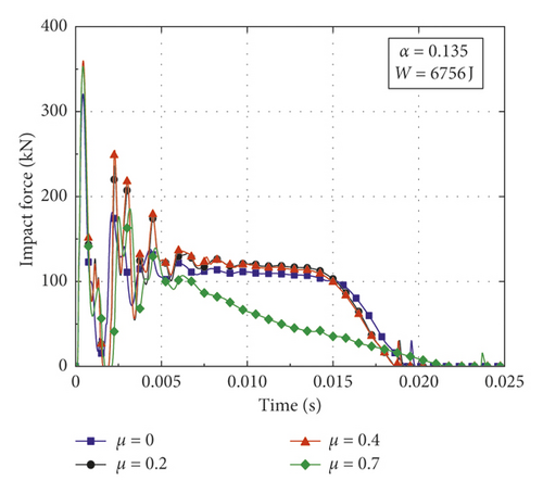
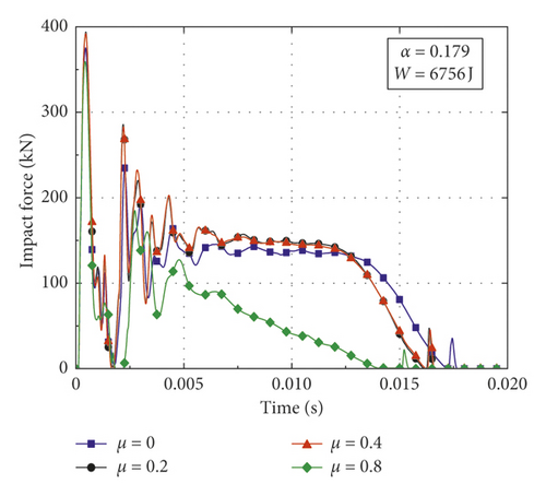
Figures 4(a) and 4(b) show the comparison of impact force-time histories with different axial load ratios when W = 6756 J. It is noticed that the variation patterns of impact force are similar among the two groups of CFST members (A1 series and B1 series). When the axial load ratio increases from 0 to 0.2, both the peak value and the platform value of impact force increase to a certain extent, while the duration of impact force and the midspan deflection vary in an opposite way. Compared with the case in which the axial load ratio is 0.2, the impact force of CFST members has only a slight change when the axial load ratio increases to 0.4. If the axial load ratio continues to increase (A1 series reaches 0.7 and B1 series reaches 0.8), the loading process of impact force will change obviously and the impact force will unload rapidly after reaching its peak value without going through the stable platform stage. At the same time, the CFST members are prone to have the instability damage due to the second-order effect with high axial load ratios.
Figures 4(c) and 4(d) give the impact force-time histories of CFST members when the impact energy increases to 13512 J. In the range of axial load ratio less than 0.2, it is observed that the variation patterns of impact force for A2 series and B2 series are consistent with A1 series and B1 series, respectively. With the increase of axial load ratio (from 0.2 to 0.4), the platform value of impact force gradually decreases and the impact force begins to unload slowly for the CFST members of A2 series and B2 series. When the impact energy is doubled, the critical axial load ratios of A2 series and B2 series for instability damage due to the second-order effect are reduced to 0.5 and 0.6, respectively.
Figures 4(e) and 4(f) present the impact force-time histories of CFST members for A3 series and B3 series. For the CFST members of A3 series, the impact force begins to unload slowly with the axial load ratio of 0.2, and the CFST members will show the instability damage directly when the axial load ratio increases to 0.4. For the CFST members of B3 series, the impact force begins to unload slowly under the excessive impact energy even without applying the axial force. In the process of increasing the axial load ratio (from 0 to 0.4), the duration of impact force will continue decreasing and the CFST members will be destroyed due to excessive impact energy as well as high axial load ratio.
It can be concluded from the above results as follows: (1) The effects of axial force on variation pattern of impact force for CFST members are diverse. The impact force presents different shapes and characteristics under the various axial load ratios, so the corresponding impact response of CFST members is also different. (2) The steel ratio can improve the impact resistance of CFST members and increase the critical axial load ratio of CFST members for instability failure. (3) When the impact energy is within a small range, the appropriate application of axial force can improve the impact resistance of CFST members when the axial load ratio is at a low level, while the CFST members may suffer from instability damage due to the second-order effect when the axial load ratio exceeds the small range. (4) When the impact energy is high, the effect of axial force will significantly weaken the impact resistance of CFST members even in the small range of axial load ratio.
3.2. Equivalence Principle of Impact Force
4. Development of SDOF Method considering Axial Force
The classical equivalent SDOF method neglects the effect of axial force when calculating the deflection, which cannot reflect the actual stress of structural members under lateral impact. Some researchers have improved the classical equivalent SDOF method utilized in blast field considering the interaction of axial load-bending moment [31] or considering the additional lateral force caused by the second order effect [32]. In order to establish the deflection calculation method of axially loaded CFST members subjected to lateral impact in this paper, the conversion factors and resistance function are deduced on the basis of the equivalent SDOF method. Then, the differential equation of the equivalent SDOF model considering axial force and lateral impact load is established, and the deflection can be obtained by solving the differential equation. It is necessary to define appropriate basic assumptions as follows: (1) ignoring the damping of the whole impact system; (2) ignoring the initial defect and local deformation of CFST members; (3) the CFST members do not suffer from instability damage; (4) the bending deformation of CFST members is considered and the influence of shear deformation is neglected.
4.1. Equivalent SDOF Model considering Axial Force
In order to adopt the equivalent SDOF method to analyze impact response of CFST members with distributed mass and distributed stiffness, it is necessary to simplify the actual system of CFST members into an equivalent SDOF system with an equivalent lumped mass, equivalent stiffness, and equivalent impact load. The experimental and numerical models of the CFST member involved in Section 2 are simplified into the equivalent SDOF mass-spring system as shown in Figure 6.
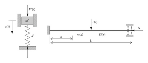
The generalized system should be transformed into the actual system through the conversion factors, and then, the deflection of CFST members can be calculated by solving the differential equation.
4.2. Derivation of Conversion Factors
According to the shape functions given above, the conversion factors, generalized bending stiffness, and generalized geometric stiffness of the equivalent SDOF system can be calculated. The results are summarized in Table 4.
| Deformation stage | KM | KF | KFM | ||
|---|---|---|---|---|---|
| Elastic stage | 192EI/L3 | 4.8N/L | 0.37 | 1.0 | 0.37 |
| Plastic stage | 0 | 4.0N/L | 0.33 | 1.0 | 0.33 |
4.3. Derivation of Resistance Function
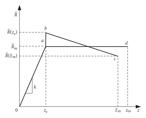
Structural resistance refers to the ability of the entire structure to withstand the effects of action (internal force, deformation, and crack, etc.), and the resistance function varies with the structural system. Since the destruction of the CFST members has a certain ductility, this paper employs the bilinear resistance function as shown in Figure 7 to carry out the analysis and calculation, which is consistent with Refs. [26, 29] and can well reflect the experimental and actual situations [47].

4.4. Dynamic Differential Equation of the Equivalent SDOF Model
When the plastic hinges are formed at the midspan and both ends of CFST members, the bending resistance of the system is the largest and the value is Rm = 8Mu/L [49], where Mu represents the plastic ultimate bending moment. Substituting the conversion factors and resistance functions obtained above into the equivalent SDOF model, the dynamic differential equations of CFST members considering axial force are established, shown as follows:
5. Assessment of SDOF Method considering Axial Force
5.1. Result Comparisons between the Proposed Calculation Method and Numerical Simulation
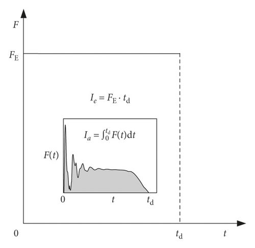
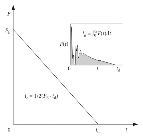
The steps for calculating the deflection of CFST members are summarized as the calculation flowchart shown in Figure 9. Firstly, according to the variation patterns of impact force-time histories, the equivalent impact loads FE (i.e. rectangular pulse load or right triangular pulse load) can be calculated through the equation (4) or (5); Secondly, the equivalent SDOF model of axially loaded CFST members subjected to lateral impact is established based on the appropriate basic assumptions discussed above, and then, the conversion factors and modified resistance functions can be derived. Finally, the deflection of CFST members can be obtained by solving dynamic differential equations (19) and (20) of the equivalent SDOF model.
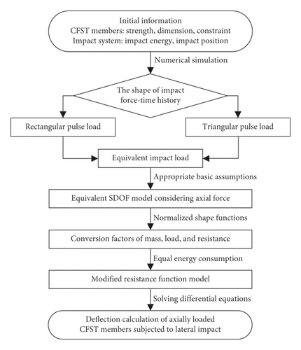
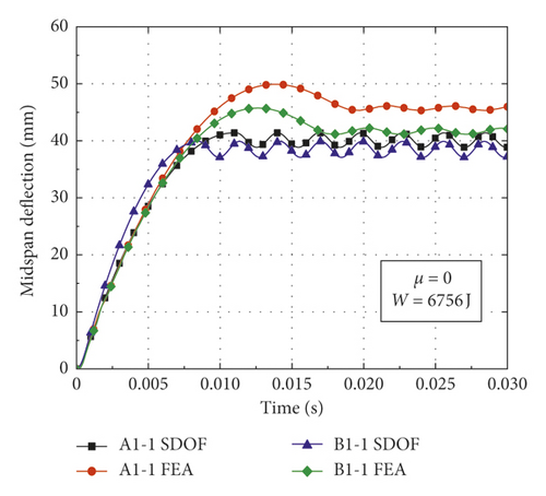
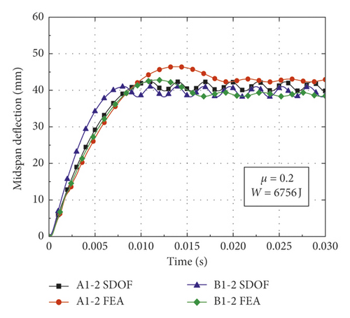
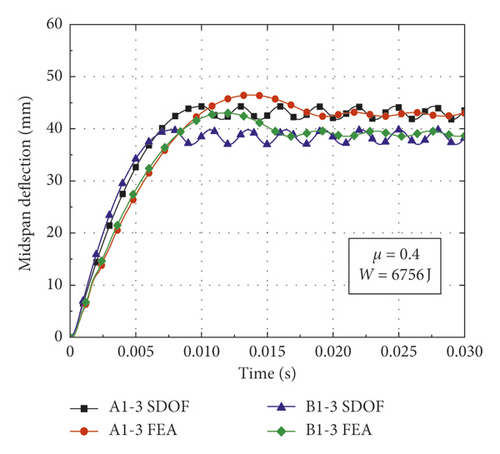
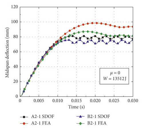
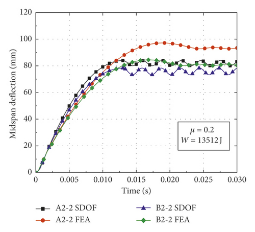
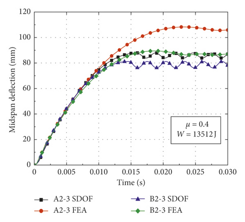
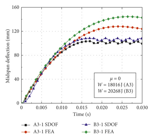
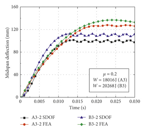
In order to validate the proposed calculation method for obtaining the deflection of CFST members, comparisons could be made between the theoretical calculation results and numerical simulation results. The CFST members with the damage pattern of fracture failure are removed from the simulation conditions, as shown in Table 3. Based on the model modification, appropriate basic assumptions, and theoretical derivation, the deflection of CFST members is calculated according to the flowchart as shown in Figure 9. The result comparisons between the proposed calculation method and numerical simulation are shown in Table 5 and Figure 10, where yFEA and ySDOF are the midspan residual deflections obtained by numerical simulation and the proposed calculation method considering axial force, respectively.
| Number | α | W (J) | μ | FE (kN) | yFEA (mm) | ySDOF (mm) | Impact load |
|---|---|---|---|---|---|---|---|
| A1-1 | 0.135 | 6756 | 0 | 96.56 | 45.72 | 40.09 | Rectangular pulse |
| A1-2 | 0.135 | 6756 | 0.2 | 105.10 | 42.65 | 41.08 | Rectangular pulse |
| A1-3 | 0.135 | 6756 | 0.4 | 109.89 | 42.82 | 43.03 | Rectangular pulse |
| A2-1 | 0.135 | 13512 | 0 | 107.45 | 93.37 | 79.15 | Rectangular pulse |
| A2-2 | 0.135 | 13512 | 0.2 | 110.60 | 93.19 | 82.01 | Rectangular pulse |
| A2-3 | 0.135 | 13512 | 0.4 | 92.58 | 105.75 | 85.83 | Rectangular pulse |
| A3-1 | 0.135 | 18016 | 0 | 118.81 | 124.21 | 101.59 | Rectangular pulse |
| A3-2 | 0.135 | 18016 | 0.2 | 189.47 | 126.80 | 99.39 | Triangular pulse |
| B1-1 | 0.179 | 6756 | 0 | 115.36 | 41.70 | 38.49 | Rectangular pulse |
| B1-2 | 0.179 | 6756 | 0.2 | 123.47 | 38.86 | 39.60 | Rectangular pulse |
| B1-3 | 0.179 | 6756 | 0.4 | 127.42 | 39.02 | 38.40 | Rectangular pulse |
| B2-1 | 0.179 | 13512 | 0 | 128.65 | 81.65 | 73.39 | Rectangular pulse |
| B2-2 | 0.179 | 13512 | 0.2 | 133.34 | 80.78 | 75.78 | Rectangular pulse |
| B2-3 | 0.179 | 13512 | 0.4 | 131.19 | 86.68 | 78.72 | Rectangular pulse |
| B3-1 | 0.179 | 20268 | 0 | 192.13 | 142.74 | 106.17 | Triangular pulse |
| B3-2 | 0.179 | 20268 | 0.2 | 221.12 | 132.94 | 110.12 | Triangular pulse |
5.2. Accuracy Analysis of the Proposed Calculation Method
In order to intuitively analyze the accuracy of the proposed calculation method, the results obtained by numerical simulation and equivalent SDOF method considering axial force are plotted in Figure 11. The best-fit line for the midspan deflections of CFST members is y = 0.8368x and the correlation factor is R2 = 0.9636, which means the proposed calculation method can be well applied to obtain the midspan deflections for axially loaded CFST members subjected to lateral impact.
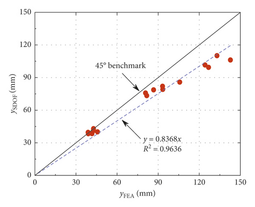
From Table 5 and Figures 10 and 11, the following observations can be made: (1) The midspan residual deflections obtained by the proposed calculation method are less than numerical simulation results. It is primarily attributable to the fact that the equivalent impact loads employed in the SDOF model are slightly lower than the actual impact loads of numerical simulation (i.e., the equivalent rectangular load is slightly lower than the platform value of impact force and the equivalent triangular load is less than the peak value of impact force), which results in the reduction of deflection obtained by the proposed calculation method. (2) The deflections calculated by equivalent rectangular pulse loads are more consistent with the simulation results than those of equivalent triangular pulse loads, which indicates that the equivalent rectangular pulse loads are more suitable for the deflection calculation of CFST members under bending deformation. (3) The changes in the initial parameters such as impact energy, steel ratio, and axial load ratio have a significant effect on the accuracy of proposed calculation method. The CFST members tend to suffer from shear failure when the impact energy exceeds a certain range, which results in an accuracy reduction of the proposed calculation method. In addition, the theoretical calculation results agree well with the simulation results when the axial load ratio is within the small range, while CFST members may occur the instability damage when the axial load ratio is beyond this range, which also reduces the accuracy of proposed calculation method. (4) The deflection time history curves of CFST members obtained by the proposed calculation method are roughly simple harmonic oscillation after entering the stability stage, which is mainly due to the fact that the effect of damping is omitted in the equivalent SDOF model.
6. Conclusions
- (1)
For the impact conditions with small input energy, the impact force shows a long platform stage and the appropriate application of axial force can improve the impact resistance of CFST members within the certain range of axial load ratio. When the CFST members encounter high impact energy, even within the small range of axial load ratio, the impact force will unload without experiencing a stable platform stage and the axial force will significantly weaken the impact resistance of CFST members.
- (2)
According to the variation patterns of impact force-time histories, the impact loads of CFST members can be equivalent to the rectangular pulse loads or right triangular pulse loads through the equivalence principle. Moreover, the results of comparison with numerical simulation indicate that the equivalent rectangular pulse loads are more suitable for the deflection calculation of CFST members under the bending deformation.
- (3)
A simplified calculation method has been proposed based on the equivalent SDOF method and appropriate basic assumptions, and it can be utilized to calculate the deflection of axially loaded CFST members subjected to lateral impact. In addition, the differential equation and resistance function of the equivalent SDOF model considering the effect of axial force have been modified and incorporated into the proposed calculation method, which can better reflect the actual stress of axially loaded CFST members subjected to lateral impact.
- (4)
The calculation accuracy has been validated by comparing with the numerical simulation, which means the proposed calculation method can be effectively applied to the deflection calculation for CFST members under impact load and axial force. The results of this investigation can provide the theoretical foundation for damage assessment and anti-impact design of axially loaded CFST members subjected to lateral impact.
Conflicts of Interest
The authors declare that there are no conflicts of interest regarding the publication of this paper.
Acknowledgments
This research was supported by the National Natural Science Foundation of China (Grant no. 51378427) and the National Key Research and Development Program of China (Grant no. 2016YFC0802205). The authors are grateful for the financial support.
Open Research
Data Availability
The data used to support the findings of this study are available from the corresponding author upon request.


