An Image Encryption Algorithm Based on Hyperchaotic System and Variable-Step Josephus Problem
Abstract
In this paper, an image encryption algorithm based on a hyperchaotic system and variable-step Josephus problem is proposed. Based on an in-depth analysis of the classic Josephus problem, a new variable-step Josephus problem that combines the pseudorandom sequence with the Josephus problem is proposed. Firstly, the hash value of the plaintext image is calculated, which is converted to the initial value of the chaotic system. Secondly, the chaotic system is iterated to generate four pseudorandom sequences X, Y, Z, and W. The sequences X, Y, and Z are input as parameters into the variable-step Josephus function to scramble the positions of the rows, pixel bits, and columns of the image, respectively. Finally, the elements of the sequence W and the image pixels are used to perform the addition operation. According to the experiments, the information entropy of the encrypted image with size 256 ∗256 reaches 7.997 and the adjacent correlations in three directions are within ±0.01. The experimental results show that image encryption algorithm proposed in this paper has plaintext sensitivity and can resist the common attacks.
1. Introduction
With the rapid development of modern information technology, more and more image information is transmitted on social networks, and many of these digital images carry private information. How to protect private information from being leaked has become a research hotspot [1]. Some traditional encryption methods such as Data Encryption Standard (DES) or Advanced Encryption Standard (AES) are mainly used for text information. Unlike text information, there are some inherent characteristics such as strong correlation and high redundancy between adjacent pixels in digital images. Therefore, the traditional encryption algorithm has the disadvantage of low efficiency when encrypting digital images [2]. Based on the huge demands for protecting information security, in recent years, many researchers have proposed a number of new encryption algorithms to protect information security [3–8]. Thus, finding a suitable image encryption algorithm has been the goal pursued by researchers.
In 1997, Fridrich proposed an encryption algorithm based on the chaotic map, which applied the chaotic system to image encryption for the first time [9]. The chaotic system is a kind of nonlinear dynamic system [10]. It has complex pseudorandomness, neither periodicity nor convergence. The chaotic system is very sensitive to the initial values of the system. Slight changes in the initial values will affect the evolution of the whole system, it is of great value in cryptography. Because of the sensitivity to the initial values and the characteristics of strong track ergodicity, the chaotic system is often used as the pseudorandom number generator. The encryption algorithm using the chaotic system has high security, which can make up for the shortcomings of the traditional encryption algorithm. In recent years, many image encryption algorithms based on chaotic systems have been proposed, and chaotic systems have gradually evolved from low-dimensional chaotic systems to hyperchaotic systems, multilevel chaotic systems, and hybrid chaotic systems [11–13]. These new chaotic systems enrich the content of cryptography.
However, most of the previous chaotic-based encryption technologies are based on low-dimensional discrete chaotic maps [14–17]. In view of the limitation of computational accuracy, low-dimensional chaotic systems have the weaknesses of small periods and fewer periodic orbits, leading to weak cryptographic systems security. In order to overcome the fixed point and dynamic key space problems of one-dimensional chaotic systems, the literature [18] upgrades two one-dimensional chaotic maps into two-dimensional chaotic maps, and then encrypts the image. Hua et al. [19] proposed a two-dimensional chaotic sequence generation model combining a sine map and logistic map in 2015. The model uses sine mapping and parameters to adjust the output of a logistic map to enhance the nonlinearity of the two-dimensional chaotic sequence. And randomness improves the security of the encryption system to a certain extent. Due to its large key space and two or more Lyapunov exponents, hyperchaotic systems have more complex and unpredictable nonlinear behaviors. They have great application potential in the field of image encryption and have aroused strong research interest among scholars. In 2014, Benyamin proposed a simple, sensitive, and secure image encryption algorithm based on hyperchaotic systems [20]. This algorithm uses the randomness of pseudorandom sequences generated by hyperchaotic systems, and uses only one scrambling process to achieve a good scrambling effect. The chaotic sequence generated by the hyperchaotic system is a pseudorandom sequence, and its structure is very complex and difficult to analyze and predict. Therefore, the hyperchaotic system can improve the security of our image encryption system. This article will also use hyperchaotic systems to increase the security of the system.
While new chaotic image encryption algorithms are constantly proposed, cryptographic analysis of the chaotic image encryption algorithms is also continually carried out. Many image encryption algorithms based on chaotic systems have been cracked due to their inability to resist selected-plaintext attacks and known-plaintext attacks [21]. Some studies combine other encryption techniques to improve the security of chaotic image encryption [22]. In 2012, Ye and Wong proposed a new algorithm for image encryption using the hyperchaotic system and DNA sequence [23]. This algorithm uses a four-dimensional hyperchaotic system to generate pseudorandom sequences, converts pseudorandom sequences into DNA molecular sequences, and performs image diffusion operations. This algorithm can effectively resist plaintext attacks and has good encryption effect. In 2018, Wang et al. proposed an encryption algorithm based on the combination of Josephus traversal and four one-dimensional chaotic systems [24], which used Josephus traversal to scramble pixel positions and the chaotic system to displace pixels. The analysis results show that the algorithm satisfies the basic requirements of image encryption algorithm. In the same year, Patro and Acharya proposed a secure multilevel permutation operation to encrypt color image [25], and the proposed encryption technique uses three levels of permutation operation to permutation color image.
To improve the coupling of the confusion and diffusion structure and improve the efficiency of encryption, image encryption algorithms based on pixel bit position permutation are widely studied. The permutation of the pixel bit can not only change the position of the bit but also diffuse the pixel value. In this paper, based on the traditional Josephus traversal method and the pseudorandom sequence generated by the hyperchaotic system, a random-step Josephus traversal method is proposed and applied to image scrambling process. This scrambling method simplifies the scrambling process by eliminating the need to sort the pseudorandom sequences, and the degree of scrambling cipher using this scrambling method is no less than that of the chaotic sequence sorting scrambling algorithm.
The remaining parts of this paper are organized as follows: Section 2 introduces the basic theory of the chaotic system and Josephus problem. Section 3 introduces the encryption scheme, and Section 4 analyzes the security of this scheme. The last section concludes the paper.
2. Fundamental Theory
2.1. Josephus Problem
The Josephus problem is a counting-out problem, and it originated from the story of the famous Jewish historian Josephus [26]. When the Jews were invaded by the Romans, Josephus and his friends were hiding in a hole with 39 Jews. These 39 Jews did not want to be caught by the enemies, so they decided to suicide. They stood in a cycle and reported numbers one by one. The man who reported the number 3 must suicide, then restart counting from the next person. However, Josephus and his friends did not want to die. How to be the last two people to be recycled? Josephus carefully calculated and placed him and his friends in the 16th and 31st positions. Finally, they escaped from the death game.
The Josephus problem is described as follows: rearranging M elements into a circle. Then, we repeat looping the circle by deleting the Nth element and restart counting by the N + 1th element [24, 27]. We repeat doing these operations until the last element is selected. The Josephus problem is expressed as a function f (M, N). For example, the solution of the function f(8, 3) is to rearrange the elements {1, 2, 3, 4, 5, 6, 7, 8} in a circle, then loop the circle, and delete the 3rd element. In this Josephus problem, the elements that are sequentially deleted in the circle are {3, 6, 1, 5, 2, 8, 4, 7}. There is another solution to these problems. Still taking f(8, 3) as an example, first we rearrange the elements {1, 2, 3, 4, 5, 6, 7, 8} into a one-dimensional sequence; then, the total of these elements is 8, we calculate mod (3, 8) = 3 and delete the 3rd element which is 3. Then, we rearrange the remaining elements into a new sequence {4, 5, 6, 7, 8, 1, 2}, because the total of the elements in the new sequence is 7, and we calculate mod (3, 7) = 3 and delete the 3rd element in the new sequence which is 6. Repeat doing these operations until the last element is selected. By using this method, the Josephus problem can be solved quickly.
In order to increase its diversity, some scholars had added the starting point S to the original rule and expanded the Josephus function as f(M, N, S). This method can choose the starting point in the Josephus circle, then the Josephus problem is more interesting. On the basis of the expanded Josephus problem, Guo et al. added the cycle direction and the number space to the Josephus problem and extended the Josephus function to f(M, N, S, D, L) [28]. The parameter D is the cycle direction. When D = 1, it represents a clockwise loop will be done, and when D = −1, it represents a counterclockwise loop will be done. The parameter L is the number space, and it represents report one number every L counts.
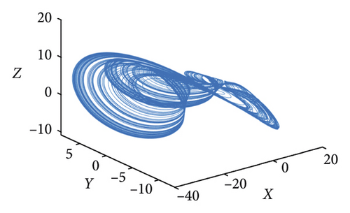
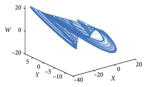
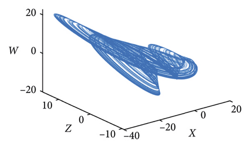
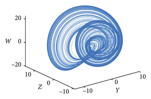
This paper continues to improve the Josephus problem based on the above expansion methods and proposes a variable-step Josephus problem. This method combines the Josephus problem with the chaotic system and expands the parameter N into a pseudorandom sequence . When traversing the Josephus circle, the parameter N in the ith looping is N = . Because the elements in sequence N′ have pseudorandomness, they can be expanded infinitely, and the solution of the Josephus problem is greatly increased. For example, when N′ = {1, 2, 3, 4, 5, 6, 7, 8}, the result of the function f(8, {1, 2, 3, 4, 5, 6, 7, 8}, 1, 1, 0) is {1, 3, 6, 4, 5, 2, 7, 8}.
The proposed method can also be used to expand parameters D and L, and it will not be described here. Finally, this expanded Josephus problem will have a solution method in M!
2.2. Hyperchaotic System
3. Encryption Scheme
The encryption scheme consists of key generation, scrambling process, and permutation process. The details of these processes are as follows.
3.1. Key Generator
Here, are the given initial values. After the initial values are obtained, the chaotic system is iterated and the values of the first 1000 iterations are discarded to remove the transient effect. Then, four pseudorandom sequences X, Y, Z, and W for scrambling and permutation are obtained.
3.2. Scrambling Method
Scrambling is a commonly used method for changing the position of the pixels. It can be applied to encrypt the sequence with a certain rule. The scrambling method used in this paper is matching the position of the elements in the original sequence with the position of the elements in the pseudorandom sequence s = {s1, s2, s3, …, sM} of equal length, and then the new sequence is obtained by rearranging the sequence s = {s1, s2, s3, …, sM} under a certain rule. The original sequence is scrambled to a new sequence according to this rule and the encrypted sequence is obtained. The flowchart of the scrambling process is shown in Figure 2. The decryption process of the scrambling method is the inverse process of encryption, and it will not be described again.
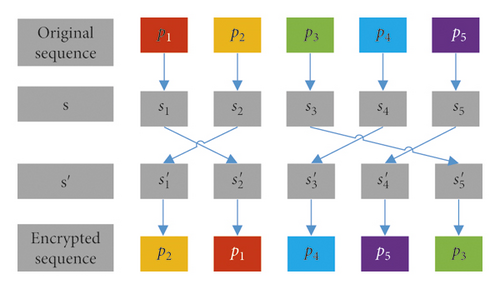
In this paper, the scrambling method is used to scramble the pixel position and the bit position. In this pixel position scrambling method, the parameter N′ in Josephus problem is generated by the hyperchaotic system and the index sequence is obtained. The pixel sequence is scrambled by the rule of s = {1, 2, 3, …, M}⟶. In the bit position scrambling method, the bit position in pixel is disordered by the fixed step size Josephus problem. The pixels in the image can be converted to 8-bit binary numbers. So, the total number M is 8, and the index sequence generated by the Josephus problem is s′ = f(8, N). Finally, the bits of the pixel are scrambled by the rules of s = {1, 2, 3, 4, …, 8}⟶.
3.3. Pixel Permutation
This paper uses a 2-bit binary number addition and subtraction method to perform a permutation operation on the pixels. In the 2-bit binary numbers, there is a special addition and subtraction rule regardless of the carry and borrow in the addition and subtraction process. Only the last two binary digits in the operation result are retained. For example, ‘10’ + ‘11’ = ‘01’ and ‘01’ − ‘10’ = ‘11’. There are 32 possible cases when using this addition and subtraction rules. These 32 cases are shown in Table 1.
| + | 00 | 01 | 10 | 11 | − | 00 | 01 | 10 | 11 |
|---|---|---|---|---|---|---|---|---|---|
| 00 | 00 | 01 | 10 | 11 | 00 | 00 | 11 | 10 | 01 |
| 01 | 01 | 10 | 11 | 00 | 01 | 01 | 00 | 11 | 10 |
| 10 | 10 | 11 | 00 | 01 | 10 | 10 | 01 | 00 | 11 |
| 11 | 11 | 00 | 01 | 10 | 11 | 11 | 10 | 01 | 00 |
When permuting two pixels with the 2-bit binary number addition and subtraction rules, the pixels should first be converted into two 8-bit binary numbers, and then the 8-bit binary numbers are split into 2-bit binary numbers. For example, using 225 and 108 for two-bit binary number addition and subtraction, first 225 and 101 should be converted into 8-bit binary digits “11100001” and “01101100”, respectively, and then the two numbers are split into 2-bit binary numbers for addition. The result of the calculation is “00001101”. We convert this number into a decimal number, and the result is 13. The two-bit binary addition and subtraction operations are reciprocal process.
3.4. Encryption Process
-
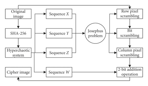
Step 1. A 256-bit binary sequence H is obtained by inputting the original image into the SHA-256 function, and the initial values of the hyperchaotic system are calculated by formula (2)
-
Step 2. Four pseudorandom sequences X, Y, Z, and W are obtained by iterating the hyperchaotic system. And in the chaotic system, the values of the first 1000 iterations are discarding to remove the transient effect.
-
Step 3. The sequence X is converted into a new matrix X1 by formula (3), and then we input each row sequence in the matrix X1 as the parameter N′ into the Josephus problem function to scramble each row pixel sequence in the original image. The cipher image I1 is obtained:
-
Step 4. Converting the sequence Y into a new matrix Y1 by formula (4), each element in matrix Y1 is in the interval [1,29]. The elements are used in matrix Y1 as the parameter N to scramble the pixel corresponding to its position in cipher image I1 to achieve pixel bit scrambling. The cipher image I2 is obtained:
(4)
-
Step 5. The sequence Z is converted into a new matrix Z1 by formula (5), and then we input each column sequence in the matrix Z1 as the parameter N′ into the Josephus problem function to scramble each column pixel sequence in cipher image I2. The cipher image I3 is obtained:
-
Step 6. Converting the sequence W into a new matrix W1 by formula (6), each element in matrix W1 is in the interval [0, 255]. A cipher image C is obtained by using a 2-bit binary number addition operation to encrypt the cipher image I3 with matrix W1:
The flowchart of the encryption process is shown in Figure 3. The decryption process of the encryption algorithm is the inverse process of encryption, which will not be described again.
4. Simulation Results and Security Analysis
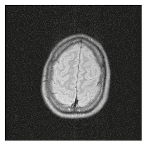
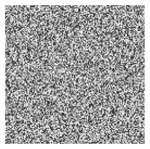
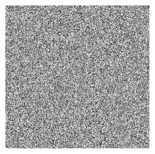
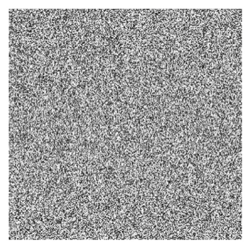
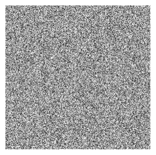
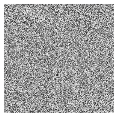
The simulation experiment platform is Matlab R2018a, and the computer configuration environment is Windows 7, 4.00 GB RAM, Intel (R) Core (TM) i3-4130 CPU @3.4 GHz. This encryption algorithm is used to encrypt any size of the digital image. The original images cameraman 128 × 128, cameraman 256 × 256, brain 256 × 256, white 256 × 256, black 256 × 256, and their cipher images encrypted by this encryption algorithm are shown in Figure 4. The hash sequence used as the initial key is generated from the original image. The other part of the key is . The examples of cipher images listed in Figure 4 have completely lost the characteristics of the original image, and the encryption algorithm works well. Moreover, the algorithm is lossless and the decrypted image is identical with the original image.




4.1. Key Analysis
4.1.1. Key Space Analysis
This encryption algorithm uses the SHA-3 algorithm to generate the encryption key. And the initial values of the hyperchaotic system are generated by the key. Among them, the key space of SHA-3(256) is 2128, and the key spaces of the four initial values of the hyperchaotic system are 1040. Therefore, the key space of the encryption algorithm is 3.4028 × 1078.
4.1.2. Encryption Key Sensitivity Analysis
The expected values of NPCR and UACI are 100% and 33.4635%, respectively. Taking the cameraman 256 × 256 image as an example, when the key is changed by 10−12, the values of NPCR and UACI between the cipher image and the original cipher image are shown in Table 2. It can be seen from the comparison that the algorithm has strong sensitivity to key encryption.
| Initial values | NPCR (%) | UACI (%) |
|---|---|---|
| x 1 + 10−12 | 99.6215 | 33.3213 |
| y 1 + 10−12 | 99.6093 | 33.4764 |
| z 1 + 10−12 | 99.6002 | 33.7886 |
| w1 + 10−12 | 99.6307 | 33.6475 |
4.1.3. Decryption Key Sensitivity Analysis




When the key changes slightly, the indicators of the difference between the decrypted image and the original image are shown in Table 3. By comparison, the algorithm has strong sensitivity to key decryption. When the key changes slightly, the image cannot be decrypted.
| Initial values | NPCR | UACI | MSE | PSNR |
|---|---|---|---|---|
| x1 + 10−10 | 99.5895 | 33.9695 | 11341 | 7.5841 |
| y1 + 10−10 | 99.5819 | 33.2737 | 11509 | 7.5201 |
| z1 + 10−10 | 99.5560 | 33.4204 | 11582 | 7.4928 |
| w1 + 10−10 | 99.6200 | 33.4349 | 115891 | 7.4903 |
4.2. Differential Attack Analysis
The differential attack analysis refers to making minor changes to the original image and encrypting it, then analyzing the cipher image and analyzing its sensitivity to plaintext. NPCR (number of pixels change rate) and UACI (unified average changing intensity) are used to measure the ability of resisting differential attacks. Table 4 lists the values of NPCRs and UACIs between the cipher images and the cipher images when the original image changes by 1 bit. The data in Table 4 are close to the theoretical values. This reflects that there is a strong correlation between the cipher image encrypted by this encryption algorithm and the original image. Even if the original image changes slightly by 1 bit, the cipher image encrypted by this encryption algorithm will undergo a thorough change. This algorithm is effective against differential attacks.
| Images | NPCR | UACI |
|---|---|---|
| Cameraman 128 ∗128 | 99.6216 | 33.2842 |
| Cameraman 256 ∗256 | 99.6109 | 33.3735 |
| Cameraman 512 ∗512 | 99.5941 | 33.4795 |
| Brain 128 ∗128 | 99.5544 | 33.3126 |
| Brain 256 ∗256 | 99.5789 | 33.3460 |
| Brain 512 ∗512 | 99.6094 | 33.4677 |
| White 128 ∗128 | 99.6033 | 33.7762 |
| White 256 ∗256 | 99.6506 | 33.4553 |
| White 512 ∗512 | 99.6109 | 33.5130 |
4.3. Histogram Analysis
The histogram is an indicator of statistics in the image, which reflects the total pixel numbers of each value in the image [30]. The histograms of the original cameraman 256 × 256 image and brain 256 × 256 image and their cipher images are listed in Figure 6. By comparing and analyzing the histograms of the original images and the cipher images, it can be seen that the distribution of the pixel values of the original images is relatively centralized, which has certain statistical characteristics and has no resistance to brute force attacks. However, the pixels of cipher image are distributed more uniform, which breaks the rule of distribution of pixels and does not have statistical characteristics. The attacker cannot use statistical characteristics to restore the original information of the image, so it can resist statistical attacks well.
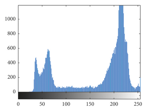
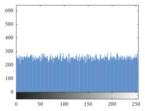
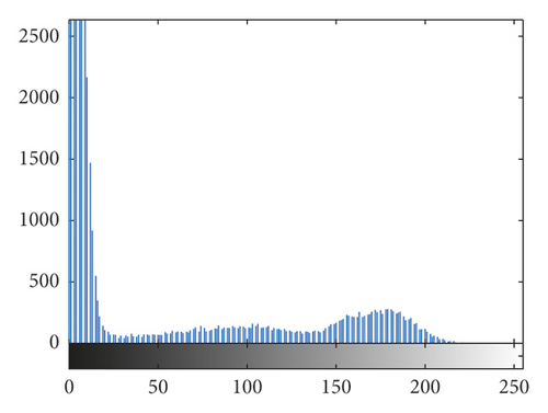
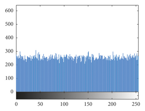
The histogram obeys the chi-square distribution with 255 degrees of freedom. Given a significant level of α, make , namely, , accept the hypothesis. When a significant levels α = 0.01, 0.05, and 0.1, there are . The chi-square distribution of some images is shown in Table 5. The commonly used significant level is α = 0.05, and all the cipher images in Table 5 passed the test. By comparison, it can be seen that the algorithm greatly changes the histogram distribution of the image and has a good ability to break the statistical characteristics of the plain images.
| Images | Plain images | Cipher images | Results |
|---|---|---|---|
| Lena 256 × 256 | 39851.3281 | 244.8906 | Passed |
| Cameraman 256 × 256 | 161271.875 | 215.1563 | Passed |
| Baboon 256 × 256 | 79056.9063 | 204.2656 | Passed |
| Boat 256 × 256 | 100853.492 | 254.9766 | Passed |
| Brain 256 × 256 | 1044635.67 | 264.0469 | Passed |
4.4. Information Entropy Analysis
Table 6 lists some information entropies of the images encrypted by the proposed encryption algorithm. By comparison, the cipher images have good information entropies, which is close to the ideal value of 8, and the cipher images have good randomness.
| Images | Entropies | |
|---|---|---|
| Original images | Cipher images | |
| Cameraman 128 ∗128 | 6.8794 | 7.9873 |
| Cameraman 256 ∗256 | 6.9046 | 7.9976 |
| Cameraman 512 ∗512 | 6.9102 | 7.9994 |
| Brain 128 ∗128 | 4.9891 | 7.9854 |
| Brain 256 ∗256 | 5.0330 | 7.9971 |
| Brain 512 ∗512 | 5.4498 | 7.9993 |
| White 128 ∗128 | 0 | 7.9891 |
| White 256 ∗256 | 0 | 7.9973 |
| White 512 ∗512 | 0 | 7.9993 |
| Black 256 ∗256 | 0 | 7.9973 |
In formula (13), k represents the total blocks. S1, S2,…,Sk are nonoverlapping blocks with TB pixels randomly selected in the image, and H(Si) means the entropy of the chosen pixels in Si. When k = 30 and TB = 1936, the results of the local Shannon entropy are shown in Table 7. It can be seen from the results that the cipher image possesses high randomness.
| Images | Original images | Cipher images |
|---|---|---|
| Cameraman 256 ∗256 | 5.5319 | 7.9037 |
| Brain 256 ∗256 | 4.6936 | 7.8998 |
| White 256 ∗256 | 0 | 7.9033 |
| Lena 256 ∗256 | 6.5355 | 7.9040 |
4.5. Correlation Analysis
For the original images, the values of adjacent pixels in most regions are very close. The correlation between the values of adjacent pixels in the image is very strong. Figure 7 shows the correlation analysis of the cameraman plain image and cipher image in three directions. Breaking the strong correlation between adjacent pixels is of great significance to resist statistical attacks. The calculation method of correlation coefficient between adjacent pixels is shown in formula (14).
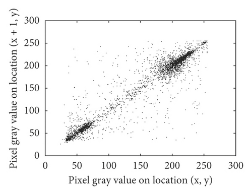
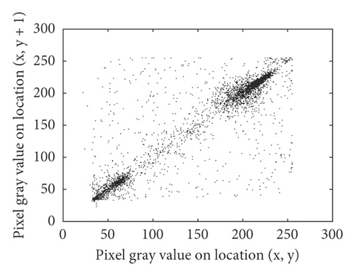
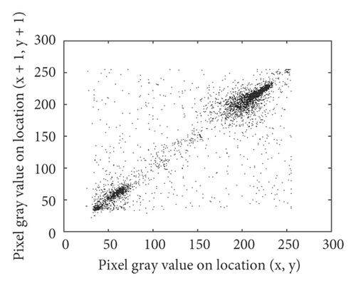


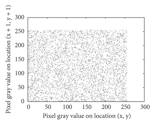
We randomly selected 5000 pairs of pixels to calculate the correlation coefficients of the original image and cipher image in horizontal, vertical, and diagonal directions. The statistical results are shown in Table 8. Statistical results show that in the original image, the correlations between randomly selected pixels are very strong, while in the cipher image, the correlation coefficients between pixels are close to 0. The proposed algorithm can better disturb the correlations between pixels, so it can better resist statistical attacks.
| Images | Correlation | |||||
|---|---|---|---|---|---|---|
| Original image | Encrypted image | |||||
| Horizontal | Vertical | Diagonal | Horizontal | Vertical | Diagonal | |
| Cameraman 128 ∗128 | 0.9530 | 0.9084 | 0.8812 | −0.0162 | 0.0015 | 0.0053 |
| Cameraman 256 ∗256 | 0.9573 | 0.9134 | 0.9066 | −0.0046 | 0.0011 | 0.0159 |
| Cameraman 512 ∗512 | 0.9906 | 0.9799 | 0.9710 | 0.0082 | 0.0019 | 0.0088 |
| Brain 128 ∗128 | 0.9829 | 0.9772 | 0.9637 | −0.0049 | 0.0004 | −0.0057 |
| Brain 256 ∗256 | 0.9857 | 0.9832 | 0.9779 | −0.0095 | −0.0035 | −0.0002 |
| Brain 512 ∗512 | 0.9969 | 0.9961 | 0.9934 | −0.0046 | 0.0073 | 0.0063 |
| White 128 ∗128 | — | — | — | 0.0002 | 0.0043 | −0.0002 |
| White 256 ∗256 | — | — | — | 0.0164 | −0.0011 | 0.0003 |
| White 512 ∗512 | — | — | — | 0.0055 | 0.0037 | 0.0056 |
| Black 256 ∗256 | — | — | — | 0.0112 | −0.0027 | 0.0040 |
4.6. Noise Attack Analysis
In the process of information transmission, it is often interfered by various kinds of noise, resulting in signal distortion. Common noise interferences include Gaussian noise, Poisson noise, and salt and pepper noise. The recovery ability of cipher disturbed by noise is one of the standards to evaluate the performance of encryption algorithm. Here, the salt and pepper noise with intensity of 0.01, 0.05, and 0.1 are interfered to the cipher, and the decrypted images are shown in Figure 8.
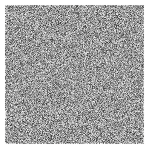
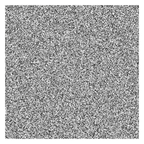
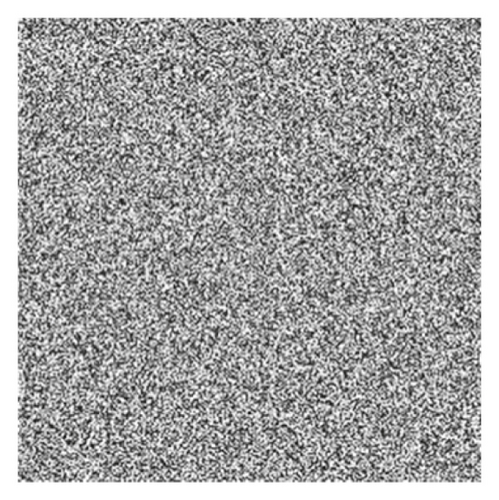


Correlations, NPCR, UACI, MSE, and PSNR are used to measure the recovery degree of the algorithm suffered from noise attack, and the details are shown in Table 9. According to the data in Table 9, the encryption algorithm has a strong recovery ability against the noise interference and can resist the noise attack very well.
| Noisy intensity | Correlations | NPCR | UACI | MSE | PSNR | ||
|---|---|---|---|---|---|---|---|
| Horizontal | Vertical | Diagonal | |||||
| 0 | 0.9573 | 0.9134 | 0.9066 | 0 | 0 | 0 | Inf |
| 0.01 | 0.9330 | 0.8939 | 0.8710 | 1.0391 | 0.3646 | 123.4764 | 27.2150 |
| 0.05 | 0.8324 | 0.8083 | 0.7852 | 4.8996 | 1.7195 | 585.6302 | 20.4546 |
| 0.1 | 0.7301 | 0.7138 | 0.7092 | 9.9579 | 3.4740 | 1172 | 17.4417 |
4.7. Data Loss Attack Analysis
Data loss attacks are attacks that intercept cipher images and delete some data. A certain amount of data are lost after the cipher image is attacked. If the recovery ability of the decryption algorithm is bad, the decrypted image of the cipher image after losing information cannot provide enough effective information. The test and analysis of data loss attacks refers to deleting some pixels of cipher image, then comparing, and analyzing the decrypted image with the original image through corresponding decryption algorithm, and its statistic recovery degree. Figure 9 shows the cipher images and corresponding decrypted images after data loss attacks.
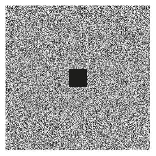
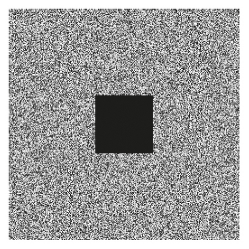


Correlations, MSE, PSNR, NPCR, and UACI are as indicators to measure the similarity of the two images. Table 10 lists the indicators of decrypted cameraman images after data loss attacks. Through comparison, it can be seen that the algorithm has recovery ability when it is attacked by data loss and has resistance ability to data loss attacks.
| Images | Correlations | NPCR | UACI | MSE | PSNR | ||
|---|---|---|---|---|---|---|---|
| Horizontal | Vertical | Diagonal | |||||
| Original image | 0.9573 | 0.9134 | 0.9066 | 0 | 0 | 0 | 0 |
| 1/64 | 0.9170 | 0.9032 | 0.8626 | 1.5564 | 0.5450 | 185.8057 | 25.4402 |
| 1/16 | 0.8127 | 0.7787 | 0.7647 | 6.2302 | 2.1481 | 723.7883 | 19.5347 |
| 1/4 | 0.5053 | 0.4704 | 0.4504 | 24.9039 | 8.5963 | 2887.4 | 13.5257 |
4.8. Classical Attack Analysis
There are four classical types of attacks: cipher-only attack (COA), known-plaintext attack (KPA), chosen-cipher attack (CCA), and chosen-plaintext attack (CPA). Among these four classical types of attacks, the COA refers to the attack performed under the cipher is known; the KPA refers to the attack under attacker masters a certain plaintext and the corresponding cipher; the CCA refers to when the attacker uses this encryption algorithm to construct the cipher corresponding to plaintext; the CPA refers to when the attacker knows the plaintext corresponding to a certain number of ciphers. In these four attack methods, if the encryption algorithm can effectively resist CPA, it must be able to resist the other three classical types of attack methods.
Attacker mostly use special image, such as white and all black to attack the image encryption methods and find the key. In this proposed algorithm, the scramble process and the pixel permutation process all related to the hyperchaotic system, and the initial values of the hyperchaotic system are very sensitive to the plain images; this has been proven in the key analysis and differential attack analysis, and so this algorithm can resist the CPA very well. The proposed algorithm can effectively resist the four classic attacks. Figure 4 shows the encryption results of all-black and all-white images of size 256 × 256. Tables 6 and 8 show the information entropy and three kinds of correlation of images.
4.9. Performance Comparison Analysis
This section lists and analyzes the security analysis of some image encryption algorithms in the references. The comparison analysis of the literature results can illustrate the security of the encryption algorithm very well. Table 11 lists some security analysis indicators of the encryption algorithm. It can be shown in Table 11 that the proposed encryption algorithm has good encryption performance and can be applied in the field of image encryption.
| Method | NPCR (%) | UACI (%) | Entropy | Correlations | ||
|---|---|---|---|---|---|---|
| Horizontal | Vertical | Diagonal | ||||
| [24] | 99.5590 | 33.4439 | 7.9971 | 0.0047 | −0.0066 | 0.0031 |
| [28] | 99.6047 | 33.5050 | 7.9963 | −0.0074 | 0.0069 | −0.0191 |
| [31] | 99.5620 | 31.1169 | — | 0.0002 | 0.0027 | 0.0031 |
| [17] | 99.60 | 33.4495 | 7.9031 | 0.0094 | 0.0023 | −0.0031 |
| [32] | 99.6445 | 33.6711 | 7.9975 | 0.0072 | −0.0113 | −0.0065 |
| [33] | 99.6124 | 33.6435 | 7.9976 | 0.0010 | −0.0048 | −0.0080 |
| [34] | 99.6114 | 33.4682 | 7.9972 | 0.0014 | 0.0027 | −0.0004 |
| Proposed | 99.6109 | 33.3735 | 7.9976 | −0.0046 | 0.0011 | 0.0159 |
4.10. Randomness Test of Cipher Image
SP800 is a series of guidelines on information security issued by the National Institute of Standards and Technology (NIST). In the NIST standard series of documents, although NIST SP is not a formal statutory standard, in actual work, it has become a de facto standard and authoritative guide widely recognized by the United States and the international information security community. This paper selects 14 test methods given in SP800-22 Revision la to test the random characteristics of cipher images encrypted by the proposed algorithm. The test results of the 14 test indicators and cipher random performance are shown in Table 12. When the test result is greater than 0.01, it means that the test object is random. Therefore, the image encrypted with this encryption algorithm has good random performance.
| Test items | Encrypted cameraman image | Encrypted Lena image | Encrypted white image |
|---|---|---|---|
| The frequency (monobit) test | 0.0145 | 0.3445 | 0.0145 |
| Frequency test within a block | 0.5579 | 0.2092 | 0.5579 |
| The runs test | 0.9938 | 0.4367 | 0.9938 |
| Tests for the longest-run-of-ones in a block | 0.2798 | 0.7677 | 0.2798 |
| The binary matrix rank test | 0.0223 | 0.1924 | 0.0225 |
| The discrete Fourier transform (spectral) test | 0.9600 | 0.3087 | 0.9600 |
| The nonoverlapping template matching test | 0.0775 | 0.0478 | 0.0775 |
| The overlapping template matching test | 0.3450 | 0.5307 | 0.3450 |
| Maurer’s “universal statistical” test | 0.1878 | 0.0182 | 0.1878 |
| The serial test | 0.0161 | 0.4132 | 0.0161 |
| 0.8952 | 0.6253 | 0.8952 | |
| The approximate entropy test | 0.8776 | 0.9952 | 0.8776 |
| The cumulative sums (CUSUMs) test | 0.4752 | 0.8580 | 0.4752 |
| 0.9431 | 0.6384 | 0.9431 | |
| The random excursions test | 0.3075 | 0.0178 | 0.3075 |
| 0.4309 | 0.0364 | 0.4309 | |
| 0.9371 | 0.0595 | 0.9371 | |
| 0.8469 | 0.0869 | 0.8469 | |
| 0.8645 | 0.2959 | 0.8645 | |
| 0.1806 | 0.6863 | 0.1806 | |
| 0.2538 | 0.7197 | 0.2538 | |
| 0.4315 | 0.4917 | 0.4315 | |
| The random excursions variant test | 0.6441 | 0.2875 | 0.6441 |
| 0.5550 | 0.3591 | 0.5550 | |
| 0.6597 | 0.3490 | 0.6597 | |
| 0.8183 | 0.3757 | 0.8183 | |
| 0.7190 | 0.3885 | 0.7190 | |
| 0.8103 | 0.1848 | 0.8103 | |
| 0.8203 | 0.0682 | 0.8203 | |
| 0.9415 | 0.0334 | 0.9415 | |
| 0.6567 | 0.0097 | 0.6567 | |
| 0.4849 | 0.2926 | 0.4849 | |
| 0.2126 | 0.9798 | 0.2126 | |
| 0.0649 | 0.7537 | 0.0649 | |
| 0.0187 | 0.7909 | 0.0187 | |
| 0.0049 | 0.9650 | 0.0049 | |
| 0.0005 | 0.8222 | 0.0005 | |
| 0.0009 | 0.7611 | 0.0009 | |
| 0.0091 | 0.6836 | 0.0091 | |
| 0.0349 | 0.5373 | 0.0349 |
4.11. Complexity Analysis
4.11.1. Speed Analysis
The simulation platform and the computer configuration environment are shown in Section 4. Table 13 shows the encryption time to encrypt common images using the proposed algorithm. It can be seen that the proposed algorithm can encrypt the original image very fast.
| Images | Encryption speed (seconds) |
|---|---|
| Lena 256 ∗256 | 1.112 |
| Cameraman 256 ∗256 | 1.256 |
| White 256 ∗256 | 1.239 |
| Boat 256 ∗256 | 1.316 |
4.11.2. Computational Complexity Analysis
When the height and width of the original image are M and N, respectively, the computational complexity of generating the hyperchaotic system is O(4 ∗M ∗N), the computational complexity of two Josephus scramble process is O(2 ∗M ∗N), the computational complexity of bit scramble is O(8 ∗M ∗N), and the computational complexity of pixel permutation is O(M ∗N).
4.12. Test Images of USC-SIPI Miscellaneous Database
In order to further verify the performance of this scheme. The proposed scheme has been tested on the USC-SIPI miscellaneous database. Performance evaluations include differential attack, correlation coefficients, and information entropy. The results are shown in Table 14.
| Image | Information entropy | NPCR | UACI | Correlation coefficient | |||
|---|---|---|---|---|---|---|---|
| Horizontal | Vertical | Diagonal | Diagonal | ||||
| 5.1.09 | 7.99724 | 99.6399 | 33.4279 | 0.0049 | 0.0116 | 0.0012 | −0.0029 |
| 5.1.10 | 7.99723 | 99.6048 | 33.4674 | 0.0029 | 0.0030 | 0.0016 | 0.0180 |
| 5.1.11 | 7.99653 | 99.5941 | 33.4989 | −0.0019 | 0.0090 | −0.0018 | −0.0094 |
| 5.1.12 | 7.99717 | 99.5850 | 33.4592 | −0.0267 | −0.0017 | −0.0018 | −0.0012 |
| 5.1.13 | 7.99692 | 99.6567 | 33.3297 | −0.0013 | 0.0074 | 0.0093 | −0.0124 |
| 5.1.14 | 7.99761 | 99.5819 | 33.5271 | 0.0072 | 0.0022 | 0.0019 | 0.0026 |
| 5.2.08 | 7.99928 | 99.6281 | 33.5026 | −0.0026 | 0.0183 | −0.0028 | −0.0099 |
| 5.2.09 | 7.99935 | 99.6181 | 33.4418 | −0.0017 | 0.0228 | 0.0177 | 0.0132 |
| 5.2.10 | 7.99929 | 99.6098 | 33.4395 | 0.0072 | 0.0131 | −0.0072 | 0.0053 |
| 7.1.01 | 7.99934 | 99.6208 | 33.3999 | 0.0200 | −0.0252 | −0.0005 | 0.0198 |
| 7.1.02 | 7.99923 | 99.5880 | 33.4919 | 0.0063 | 0.0164 | −0.0153 | 0.0212 |
| 7.1.03 | 7.99927 | 99.6063 | 33.4398 | 0.0234 | −0.0156 | 0.0029 | 0.0358 |
| 7.1.04 | 7.99941 | 99.6037 | 33.5254 | 0.0015 | 0.0278 | 0.0150 | 0.0141 |
| 7.1.05 | 7.99929 | 99.5987 | 33.4558 | 0.0073 | 0.0027 | 0.0167 | −0.0143 |
| 7.1.06 | 7.99933 | 99.6014 | 33.3711 | 0.0228 | −0.0036 | −0.0148 | −0.0021 |
| 7.1.07 | 7.99922 | 99.6101 | 33.4604 | 0.0021 | −0.0022 | 0.0025 | −0.0014 |
| 7.1.08 | 7.99924 | 99.6159 | 33.4180 | 0.0108 | −0.0074 | −0.0048 | 0.0103 |
| 7.1.09 | 7.99926 | 99.6128 | 33.4841 | 0.0031 | −0.0033 | −0.0148 | −0.0007 |
| 7.1.10 | 7.99928 | 99.6056 | 33.4488 | 0.0088 | −0.0112 | 0.0056 | −0.0012 |
| Boat 0.512 | 7.99922 | 99.6407 | 33.4799 | −0.0011 | −0.0035 | 0.0005 | −0.0003 |
| Gray 21.512 | 7.99919 | 99.6181 | 33.4631 | −0.0047 | 0.0035 | 0.0011 | 0.0024 |
| Ruler 0.512 | 7.99927 | 99.6178 | 33.4648 | 0.0016 | 0.0042 | 0.0021 | 0.0039 |
5. Conclusions
By analyzing and improving the Josephus problem, an image encryption algorithm based on the hyperchaotic system and variable-step Josephus problem is proposed in this paper. This method combines pseudorandom sequences generated by the hyperchaotic system with the Josephus problem, adds rules for the Josephus problem, and adds a method for scrambling pixel positions. The experimental results of the encryption algorithm show that the algorithm has a large key space to resist brute attacks and also can resist statistical attacks, differential attacks, data loss attacks, and other typical attacks. It can be widely used in the security transmission of images.
Conflicts of Interest
The authors declare that they have no conflicts of interest.
Acknowledgments
The work for this paper was supported by the Key Research and Development Program of Henan Province (grant nos. 202102210177 and 192102210134) and the National Natural Science Foundation of China (grant nos. 61602424 and U1804262).
Open Research
Data Availability
The data used to support the findings of this study are included within the article.


