Study on Thermal Unstable Vibration of Rotor under Journal Whirl with Large Amplitude in Journal Bearing
Abstract
To investigate the thermal unstable vibration caused by journal whirls with large amplitude in journal bearing, an analysis model of lubricant film thickness is established. The journal surface temperature distribution is solved, and the reason for journal surface temperature difference appearance and its influence on rotor vibration are analyzed. Taking a turbogenerator as an example, the journal surface temperature difference and the induced rotor thermal bending under synchronous whirl in the bearing are calculated. Meanwhile, an engineering vibration fault with its treatment is presented. Results show that, the journal surface circumferential temperature difference is caused by viscous shearing within lubricant film under journal whirls with large amplitude in journal bearing. The direction of temperature difference is related to the direction of unbalanced force acting on journal. The temperature difference causes rotor thermal bending, which can be converted to a thermal unbalance on the rotor. The rotor vibration is caused by both thermal and initial unbalance. When the rotor is running below or at the critical speed, the vibration is on the increase until it leads to instability of the rotor eventually. When the rotor is running above the critical speed, the rotor vibration fluctuates periodically. Reducing the initial (mechanical) unbalances decreases the rotor vibration and the journal surface circumferential temperature difference.
1. Introduction
Rotor vibration problem of rotating machinery can be extremely frustrating and may lead to greatly reduced reliability. The factors causing rotor vibration are various, including but not limited to: poor stability of bearing system [1, 2], mass unbalance of rotor [3, 4], asymmetric loading and asymmetric aerodynamic forces [5, 6]. In recent years, the unstable vibration in rotor systems caused by rotor thermal deformation has gradually increased. The rub between dynamic and static components is one of the most common causes for unstable vibration faults. The asymmetric temperature difference appears on shaft surface when rub occurs. It results in rotor thermal bending, which leads to unstable vibration [7–9]. The previous studies mainly concentrate on rub between seals and shaft. However, there is another kind of unstable vibration fault which is similar to rub [10–12]. Unfortunately, no rub point can be found when cylinders are opened. The causes of the faults are still under exploring.
Morton effect is a synchronous vibration phenomenon that results from journal surface temperature difference caused by viscous shearing within lubricant film. The journal surface temperature difference results in temporary rotor thermal bending, which leads to an increase in rotor vibration. The journal surface temperature distribution in journal bearing is uniform in traditional views [13]. However, de Jongh, Morton [14] and Tong et al. [15] indicated that journal surface temperature is unevenly distributed by theoretical and experimental studies. The temperature difference is caused by viscous shearing within lubricant film. Panara et al. [16] found the phenomenon that synchronous vibration instability of overhung rotor due to viscous shearing within lubricant film in engineering. Suh et al. [17, 18] suggested that there is a large journal surface temperature difference when the journal whirls in journal bearing. It causes temporary rotor thermal bending and leads to vibration instability of the rotor. Kirk et al. [19] proposed an analysis model for overhung rotor to study the synchronous thermal instability caused by viscous shearing within the lubricant. They pointed out that the instability of a rotor is determined by both thermal and mechanical unbalance. Most of the previous studies focused on the thermal unstable vibration of overhung rotors. It is considered that overhung rotors are sensitive to the temperature difference caused by journal whirls, and are easy to suffer from such faults. The journal whirls with large amplitude due to large unbalanced force acting on journal. The average lubricant film thickness of each point on journal surface is unevenly distributed, which can also cause thermal bending. However, little attention has been devoted to the issue at present.
In this study, considering the problem of journal whirls with large amplitude, an analysis model of lubricant film thickness is established. This study has solved the journal surface temperature distribution, and analyzed the journal surface circumferential temperature difference caused by journal whirl and its influence on rotor vibration. Meanwhile, an engineering vibration fault with its treatment is presented.
2. Journal Surface Temperature Distribution Modeling
2.1. Lubricant Film Thickness under Journal Synchronous Whirl
Figure 1 depicts the synchronous whirl elliptic orbit. The journal whirls in an elliptic orbit around its static equilibrium position Ojs in the journal bearing, under the action of unbalanced force. Points Ob and Oj are bearing center and journal center, respectively, as shown in Figure 1.
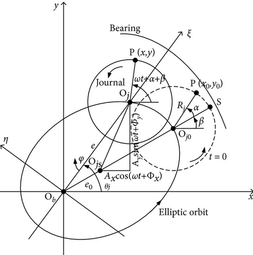
where Ax, Ay, Φx and Φy are amplitude parameters and phase parameters for elliptic orbit at x- and y-direction, respectively.
where e0 is static eccentricity, ω is whirl/journal angular speed, and Rj is journal radius.
where N is the number of grid time point in a whirl cycle, i = 1, 2, …, N.
2.2. Journal Surface Temperature Distribution
where , means the temperature difference between lubricant film temperature and ambient temperature.
where T0 is lubricant supply temperature.
3. Results and Discussion
3.1. Calculation and Analysis on Journal Surface Temperature Difference
Taking a turbogenerator as an example, the journal surface temperature distribution under journal synchronous whirls in the front bearing of the generator is calculated. Table 1 lists the parameters for journal and lubricant for calculation.
| Parameters | Value |
|---|---|
| Journal properties | |
| Journal radius Rj (mm) | 250 |
| Bearing radius clearance Cb (mm) | 0.5 |
| Lubricant properties | |
| Label (turbine oil) | #46 |
| Supply temperature T0 (°C) | 40 |
| Density ρ (kg/m3) | 860 |
| Specific heat capacity c (J/(kg•K)) | 1943 |
| Viscosity μ (Pa•s) | 0.0396 |
| Ambient temperature Ta (°C) | 20 |
| Calculation parameters | |
| Working speed n (rpm) | 3000 |
| Static eccentricity ratio ε0 | 0.5 |
| x-Direction amplitude Ax/Cb | 0.15 |
| y-Direction amplitude Ay/Cb | 0.10 |
| x-Direction phase Φx | π/6 |
| y-Direction phase Φy | π/6 |
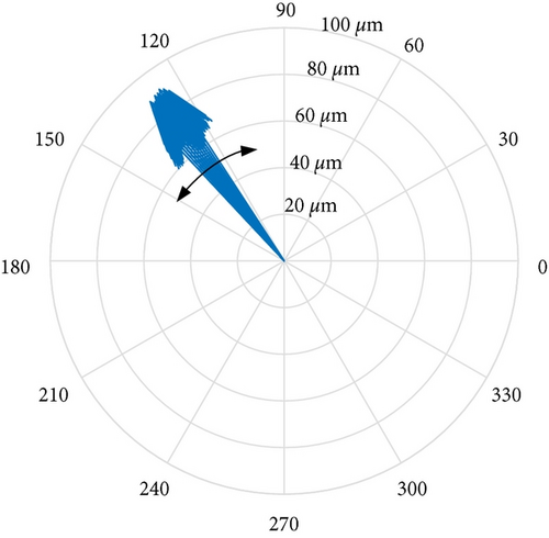
Figure 2 depicts the average lubricant film thickness distribution and the journal surface temperature distribution under different journal whirl conditions. Figure 2 indicates that: (1) the journal surface temperature distribution is uniform under no journal whirl condition. While it is nonuniform under journal whirl conditions. Taking the whirl amplitude in Table 1 as an example, the maximum journal surface temperature difference reaches 5.02℃. (2) Repositioning the direction of unbalanced force acting on the journal by 180° (can cause a change of initial phases for journal whirl of 180°) results in a change of the direction of journal surface temperature difference of about the same angle.
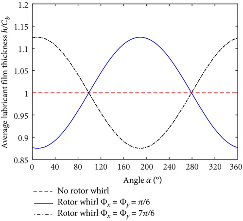
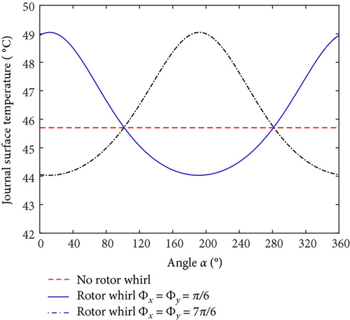
Figure 3 depicts the maximum lubricant film thickness difference and the maximum journal surface temperature difference under different whirl amplitudes (Ax = 1.5Ay). It can be observed from Figure 3 that the maximum lubricant film thickness difference and the maximum journal surface temperature difference increase with growing whirl amplitude. When the vibration reaches an excellent level (Ax < 40 μm), the maximum journal surface temperature difference is lower than 2.5℃. It is higher than 10.6℃ when the vibration exceeds the value for tripping (Ax > 125 μm).
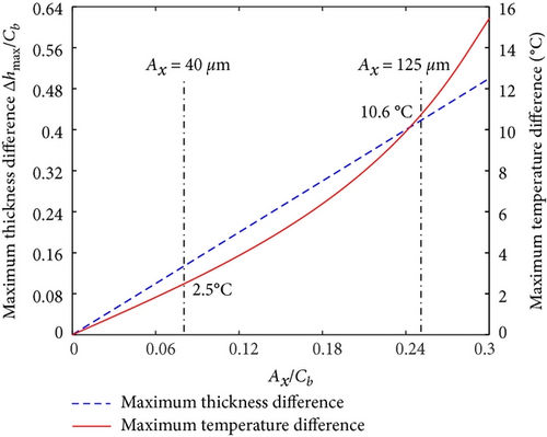
It can also be observed from Figure 3 that the maximum lubricant film thickness difference increases linearly. However, the maximum journal surface temperature difference increases nonlinearly. Its growth rate is higher under large whirl amplitude. As shown in Equation (10), the journal surface temperature is noninear with lubricant film thickness. Therefore, the journal surface temperature cannot be directly calculated by average lubricant film thickness.
3.2. Experimental Study and Comparative Analysis
An experiment was carried out to investigate the journal temperature distribution in journal bearing in Ref. [22]. The test rotor was supported by two tilting-pad journal bearings. In the nondriving end (NDE) journal, four calibrated temperature sensors were installed at 1.0 mm below the journal surface and spaced 90° apart. The testing speed was 12500 rpm.
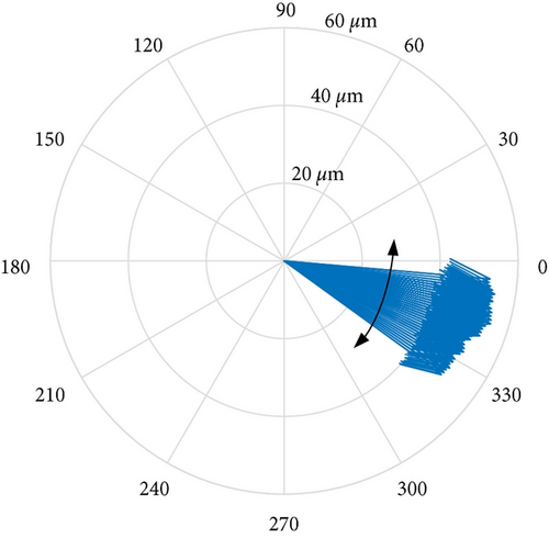
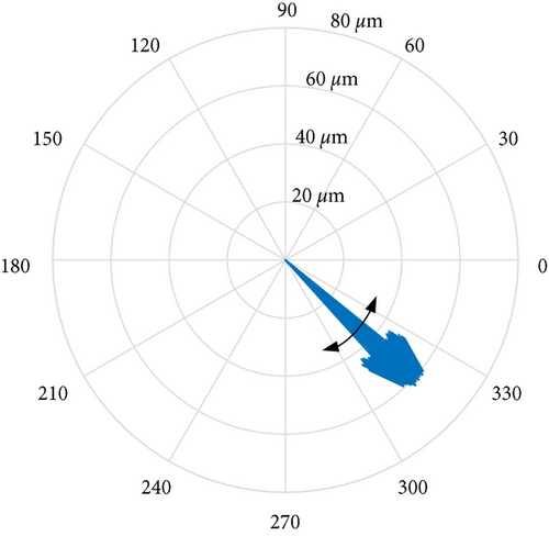
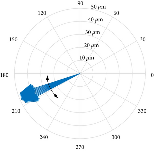
Figure 4 depicts the measurement results of journal surface temperature distribution under balanced state, and an unbalance weight applied on the shaft at a defined location at 0° and 180°, respectively. Under the balanced state, the vibration amplitude was only around 2 μm peak-to-peak at the testing speed. The journal surface temperature distribution was basically uniform, as shown in Figure 4(a). When the unbalance weight was applied at 0° or 180°, the journal whirled in the NDE bearing. The journal surface temperature differences were 6.6℃ and 6.8℃, respectively. However, the direction of temperature difference vector rotated over around 180° (see Figures 4(b) and 4(c)).
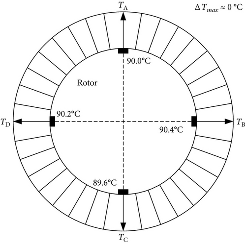
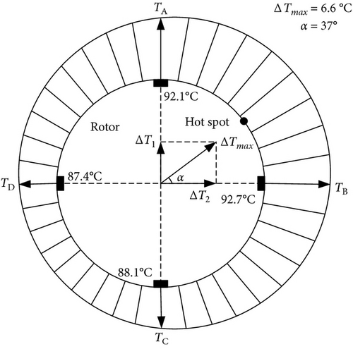
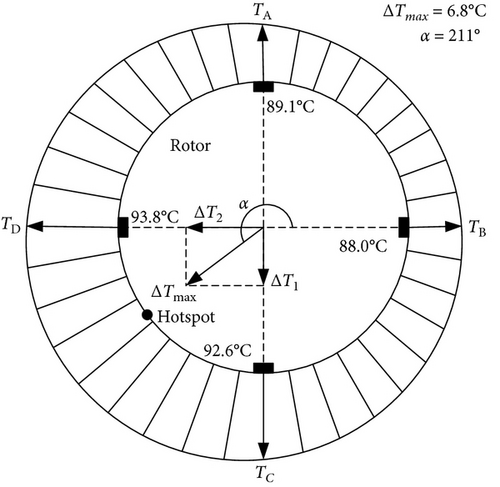
When the journal whirls with large amplitude in journal bearing, the lubricant film thickness distribution is nonuniform. Because of the different lubricant film thickness, the extrusion strength acting on lubricant film is different. It results in different heat generated by viscous shearing. When the heat transfers into the journal, the journal surface circumferential temperature difference occurs.
The phenomena shown by calculation are in accordance with experimental studies. The results show that the lubricant film thickness distribution on journal surface is nonuniform when the journal synchronously whirls in journal bearing. It causes a journal surface circumferential temperature difference. The value of journal surface temperature difference is related to the whirl orbit. The direction is associated with the direction of unbalanced force acting on journal surface.
3.3. Rotor Vibration Influenced by Temperature Difference
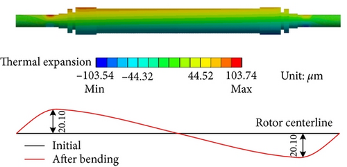
The journal surface circumferential temperature difference causes rotor thermal bending. Figure 5 depicts the simplified model of a generator rotor. Table 2 lists the sizes of generator rotor segments, and Table 3 lists the properties of rotor material. Both ends of the rotor are supported by journal bearings. The first-order critical speed (900 rpm) of the generator rotor is low, and the second-order critical speed (2600 rpm) is close to its working speed (3000 rpm). The vibration at working speed is mainly second-order mode shape. Thus, the vibrations at both ends of the rotor are antisymmetric (equal in amplitude but opposite in phase). A temperature difference of 5.02°C is imposed on the journal surfaces at both ends, with a difference of 180° in the direction. The rotor thermal deformation due to journal surface temperature differences is calculated. As shown in Figure 6, the rotor thermal bending at both ends reach 20.10 μm. The thermal bending shape is similar to the second-order mode shape. The working speed of the rotor is close to its second-order critical speed. Hence, the rotor is sensitive to unbalances. A small bending deformation has a great impact on rotor vibration.

| No. | 1 | 2 | 3 | 4 | 5 | 6 | 7 | 8 |
|---|---|---|---|---|---|---|---|---|
| Diameter (mm) | 500 | 500 | 500 | 600 | 980 | 700 | 1100 | 1000 |
| Length (mm) | 1218 | 311 | 200 | 350 | 200 | 120 | 850 | 3275 |
| Properties | Value |
|---|---|
| Density (kg/m3) | 7850 |
| Young’s modulus (GPa) | 210 |
| Poisson’s ratio | 0.269 |
| Isotropic thermal conductivity (W/(m•K)) | 50.2 |
| Coefficient of thermal expansion (/°C) | 11.59 × 10⁻⁶ |
The rotor thermal bending can be converted to a thermal unbalance Ut, which is determined by the vibration due to the initial unbalance U. The thermal and initial unbalance can be added vectorially to produce the resultant unbalance, which can change the rotor vibration. Figure 7 depicts the relationship between thermal unbalance, initial unbalance and resultant unbalance. Assuming that the initial unbalance is U0, the thermal unbalance caused by U0 at time t0 is Ut0, and the resultant unbalance is U1.
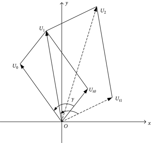

When the rotor is running below the critical speed, the lagging angle of the rotor vibration γ is less than 90°. As shown in Figure 7(a), the resultant unbalance U1 > U0. In the same way, the thermal unbalance Ut1 at time t1 can be obtained, then the resultant unbalance U2 > U1. In this process, the resultant unbalance, the rotor thermal bending and the vibration are on the increase, which will lead to instability of the rotor eventually. When the rotor is running at the critical speed, the phenomenon is similar to the above.
When the rotor is running above the critical speed, the lagging angle γ exceeds 90°. As shown in Figure 7(b), the resultant unbalance U2 < U1 < U0. In this process, the resultant unbalance and the vibration become smaller. The rotor thermal bending is gradually restored. After an interval, the vibration gradually increases again due to the initial unbalance, which will result in that the rotor vibration fluctuates periodically at a constant speed.
4. Case Study
A turbogenerator unit suffered from abnormal vibration fault of its generator. Its first- and second-order critical speed was 1052 rpm and 2736 rpm, respectively. The working speed was 3000 rpm.
4.1. Vibration Phenomenon
On-site vibration test was carried out firstly after the abnormal vibration fault had occurred. Figures 8 and 9 depict the trend analysis diagram and frequency spectrum of shaft vibrations at the front bearing (denoted as bearing A) and rear bearing (denoted as bearing B) of the generator, respectively. Figure 10 depicts the changes of vibration vectors.
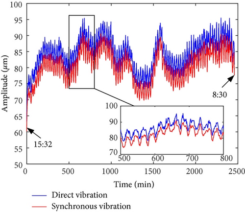
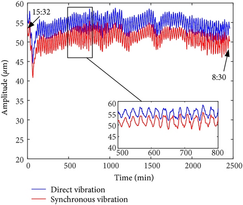
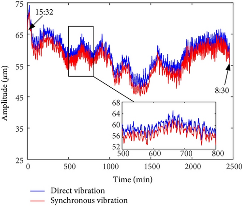

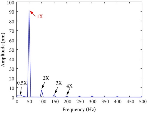
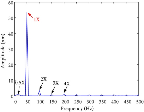
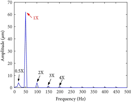
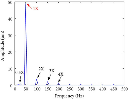
The test results showed that the shaft vibrations fluctuated periodically in constant speed operation. The synchronous component (1X, equaled to rotation frequency of the rotor) was extremely dominant in frequency spectrum. The fluctuation cycle was about 24 minutes. The direct vibration amplitude (peak-to-peak, App) of x-direction shaft vibration at bearing A fluctuated between 63.3 μm and 95.5 μm, with a fluctuation range of 32.2 μm. The 1X component accounted for 95.3%. Similarly, the periodic fluctuations also occurred on y-direction shaft vibration at bearing A, x- and y-direction shaft vibrations at bearing B. Meanwhile, the phases of vibration vectors also fluctuate periodically.
4.2. Analysis on Vibration Cause
The gaps between lubricant baffles and journals exceeded the vibration amplitudes. Thus, the lubricant baffles would not rub against the journals.
In order to find out the abnormal vibration cause, shaft vibrations and journal surface temperature at bearing A were measured on site. Table 4 lists the 1X component amplitudes (peak-to-peak, App) of shaft vibrations at bearings A and B. Figure 11 depicts the journal surface temperature distribution (before dynamic balance) at bearing A. The starting point 0° was the location of the cursor. Figure 12 depicts the journal orbit (before dynamic balance) at bearing A under synchronous vibration. The orbit center was the static equilibrium position of the journal.
| Test conditions | 1X component amplitudes (μm∠°) | Maximum temperature differences (°C) | |||
|---|---|---|---|---|---|
| Bearing A | Bearing B | ||||
| x-Direction | y-Direction | x-Direction | y-Direction | ||
| Before dynamic balance | 91∠126 | 53∠355 | 62∠316 | 49∠203 | 4.6 |
| Trial counterweights | Bearing A side: 420 g∠60°, bearing B side: 420 g∠240° | ||||
| After adding trial counterweights | 45∠306 | 44∠95 | 45∠121 | 38∠300 | 3.5 |
| Balancing counterweights | Remove trial counterweights firstly; then bearing A side: 270 g∠70°, bearing B side: 270 g∠250° | ||||
| After dynamic balance | 20∠42 | 23∠68 | 11∠172 | 18∠259 | 1.6 |
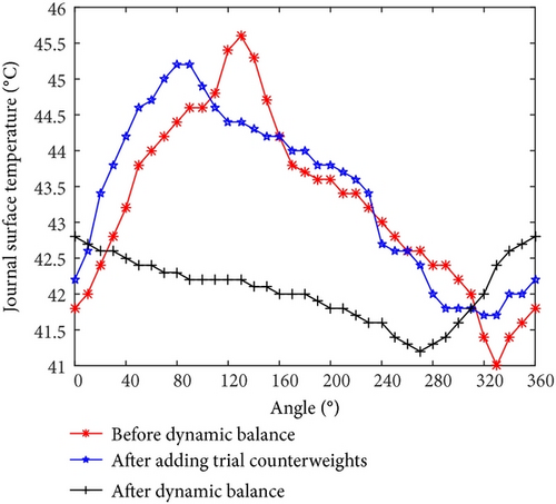
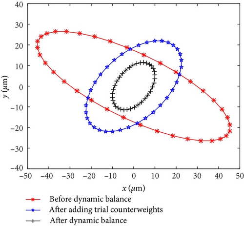
The on-site test results showed that the journal surface temperature distribution was nonuniform at bearing A. It can be confirmed that the journal surface temperature difference was caused by journal whirl with large amplitude. In other words, the periodic fluctuations of shaft vibrations were closely related to the journal whirl with large amplitude. The 1X components were extremely dominant in vibration frequency spectrums (see Figure 9). The characteristics are consistent with those of unbalance faults. The root cause for the vibration fault was a mass unbalance on the rotor.
4.3. Treatment for Vibration Fault
| Measuring points | Bearing A | Bearing B | ||
|---|---|---|---|---|
| x-Direction | y-Direction | x-Direction | y-Direction | |
| Influence coefficients (μm∠°/g∠°) | 0.324∠246 | 0.177∠79 | 0.253∠70 | 0.156∠288 |
Meanwhile, considering the vector optimization method, the balancing counterweight scheme was obtained as follows: removing the trial counterweights firstly, then adding a counterweight of 270 g∠70° at bearing A side, and a counterweight of 270 g∠250° at bearing B side.
The unit vibrations had reached a good level after on-site dynamic balance. The unit vibrations were stable with little fluctuation.
It can be observed from Figure 11 and Table 4 that the rotor vibration amplitudes decreased after adding trial counterweights and dynamic balance, indicating that the rotor unbalance reduced. Based on the regularity in Figure 3, the journal surface temperature difference would decrease. Meanwhile, the rotor vibration phases changed, indicating that the position of rotor unbalance changed. According to the calculation and experimental results shown in Sections 3.1 and 3.2, the direction of journal surface temperature difference would change. The maximum journal surface temperature difference reached 4.6°C before dynamic balance. While it was only 1.6°C after on-site dynamic balance. The whirl amplitude was larger under large vibration amplitude, and the journal surface temperature difference was also higher. Results show that reducing the initial (mechanical) unbalances not only reduces the shaft vibrations, but also decreases the journal surface circumferential temperature difference.
5. Conclusion
- (1)
The journal surface circumferential temperature difference is caused by viscous shearing within lubricant film under journal whirls with large amplitude in journal bearing. The whirl amplitude is larger under large vibration amplitude, and the journal surface temperature difference is also higher. The direction of temperature difference is related to the direction of unbalanced force acting on journal.
- (2)
The journal surface temperature difference can cause rotor thermal bending, which can be converted to a thermal unbalance on rotor.
- (3)
The rotor vibration is caused by both thermal and initial unbalance. When the rotor is running below or at the critical speed, the vibration is on the increase until it leads to instability of the rotor eventually. When the rotor is running above the critical speed, the rotor vibration fluctuates periodically.
- (4)
Reducing the initial (mechanical) unbalances not only reduces the shaft vibrations, but also decreases the journal surface circumferential temperature difference.
Nomenclature
-
- Dimensions:
-
- M = mass, L = length, t = time, T = temperature
-
- Ax, Ay:
-
- Amplitude parameters for elliptic orbit (L)
-
- A0, A1:
-
- Vibrations before and after adding counterweights
-
- c:
-
- Lubricant specific heat capacity (L2 t−2 T−1)
-
- Cb:
-
- Bearing radius clearance (L)
-
- e:
-
- Time-varying eccentricity (L)
-
- e0:
-
- Static eccentricity (L)
-
- h:
-
- Lubricant film thickness (L)
-
- :
-
- Average lubricant film thickness in a whirl cycle (L)
-
- H:
-
- Convection heat transfer coefficient (M t−3 T−1)
-
- n:
-
- Working speed (t−1)
-
- N:
-
- Number of grid time point in a whirl cycle
-
- Ob:
-
- Bearing center
-
- Oj:
-
- Journal center
-
- Oj0:
-
- Journal center at t = 0
-
- Ojs:
-
- Journal center at static equilibrium position
-
- P:
-
- A general point on journal surface
-
- P, Q:
-
- Counterweights added in dynamic balance
-
- Rj:
-
- Journal radius (L)
-
- S:
-
- Thinnest lubricant film thickness point on journal surface at t = 0
-
- t:
-
- Time (t)
-
- T:
-
- Lubricant film temperature (T)
-
- :
-
- Average journal surface circumferential temperature in a whirl cycle (T)
-
- :
-
- Temperature difference between lubricant film temperature and ambient temperature (T)
-
- T0:
-
- Lubricant supply temperature (T)
-
- Ta:
-
- Ambient temperature (T)
-
- Tb:
-
- Bearing temperature (T)
-
- Tj:
-
- Journal surface circumferential temperature (T)
-
- ΔT:
-
- Lubricant film temperature rise (T)
-
- U0:
-
- Initial unbalance (M L)
-
- U1, U2:
-
- Resultant unbalance (M L)
-
- Ut0, Ut1:
-
- Thermal unbalance (M L)
-
- α:
-
- Angle between points P and S
-
- α:
-
- Influence coefficient
-
- β:
-
- Angle between point S and horizontal position at t = 0
-
- γ:
-
- Lagging angle of rotor vibration
-
- ε:
-
- Time-varying eccentricity ratio
-
- ε0:
-
- Static eccentricity ratio
-
- θj:
-
- Angle to journal center
-
- μ:
-
- Lubricant viscosity (M L−1 t−1)
-
- φ:
-
- Circumferential angle
-
- ω:
-
- Whirl/journal angular speed (t−1)
-
- Φx, Φy:
-
- Phase parameters for elliptical orbit
-
- ξ, η:
-
- Local coordinates
-
- ρ:
-
- Lubricant density (M L−3).
Conflicts of Interest
The authors declare that they have no conflicts of interest.
Acknowledgments
The authors would like to extend their sincere thanks to staffs at National Engineering Research Center of Turbogenerator Vibration, Southeast University, China, for the support and experimental tests.
Open Research
Data Availability
The data used to support the findings of this study are available from the corresponding author upon request.


