Research on the Radial Accuracy of Ultrasonic Vibration-Assisted Single Point Incremental Forming Parts
Abstract
With the more and more complexity demands of the market, the geometric accuracy of the part has become the main factor restricting the development of single point incremental forming technology (SPIF). For this reason, with the truncated cone as the target part, the radial accuracy error generation mechanism was analyzed from the aspects of sheet springback and residual stress distribution. Four factors and three levels of surface response experiments were designed using the Box-Behnken Design (BBD) for tool head diameter, layer spacing, sheet thickness, and wall angle. The single and interactive influence law of the process parameters on the radial accuracy was obtained. In response to the above research results, the ultrasonic vibration was introduced into the process of SPIF to reduce springback by reducing residual stress. The influence of vibration parameters on the accuracy was obtained through experiments. The results showed that ultrasonic vibration could effectively improve and control the accuracy of the part.
1. Introduction
Sheet metal single point incremental forming technology (SPIF) is a new plastic forming technology with advantages of low cost, short cycle, flexible, and high degree of digital. It can meet the market demands of diversification and complication. It can be used in the fields of medical, aerospace, and automotive car [1]. However, due to excessive local stress causing the excessive concentration of strain and the suspended characteristics of the sheet, the part is prone to defects such as instability, wrinkling, cracking, and the like. In addition, the forming process involves numerous process parameters. It makes it difficult to fully meet the forming accuracy requirements of the parts and restricts its wide range of industrial applications [2].
Therefore, scholars have made many efforts in controlling deficiencies and improving accuracy. Hirt et al. [3] proposed a compound-forming method combing SPIF with deep drawing technology. Experimental results showed that the accuracy of the part had greatly improved. Duflou et al. [4] used a laser moving with tool head to preheat the forthcoming formed position. It had gotten significant results in increasing the wall angle, improving forming accuracy and reducing forming load. Guzmán et al. [5] studied the relationship between force and accuracy. He proposed a method to improve the accuracy by reducing the forming force. Hussain et al. [6] proposed the concept of stress ratio. The defects were reduced by controlling the related parameters of the stress ratio. Based on the basic structure of a simple Model Predictive Control (MPC) algorithm designed for SPIF in previous work [7], an enhanced MPC algorithm had been developed especially for Two Point Incremental Forming (TPIF) with a partial die by Lu et al. [8]. Radu et al. [9] found that the accuracy error mainly comes from the springback of the part after the tool head and the holding device are unloaded. This springback is caused by the release of residual stress that is unevenly distributed after deformation. In addition, the “pillow effect” typically occurred at the bottom circle of the truncated cone in SPIF [10]. In order to improve the poor geometric accuracy, other attempts have been presented. It includes experimental investigation of process parameters [11], hybrid ISF processes [12–14], the use of partially cut-out blanks [15], and a multistage strategy [16].
In recent years, scholars have focused on the object of springback [17], bulge and surface accuracy [18, 19]. The radial accuracy error is the main geometric error of the part, which directly affects whether the part is qualified [20, 21]. Due to a large number of process parameters involved in accuracy, no comprehensive and in-depth research results on the accuracy of the parts have been found in the publicly reported research. For this reason, the mechanism of accuracy error was deeply analyzed from two aspects: elastoplastic delamination when the sheet is deformed and residual stress distribution after unloading. Then through the BBD experiment, the single and interaction effects of process parameters on accuracy were further revealed. In view of the springback mechanism of the part, the ultrasonic vibration technology was introduced into SPIF to change the elastoplastic delamination and residual stress distribution to optimize the forming accuracy of the part.
2. Method
2.1. The Definition of Radial Accuracy Error
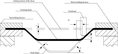
SPIF was proposed by the Japanese scholar Shigeo Matsubara in the 1990s. The basic principle is based on the “rapid prototyping technology” and “layered manufacturing.” The forming principle is shown in Figure 1. The part mode is dispersed into a series of discrete contour outline layer along the height direction. Forming tool continuously extruded layer by layer with the manner of contour line or helix so that the metal sheet local plastic deformation occurred continuously. And the final shape was obtained. D is the diameter of the forming tool, α is the wall angle, Δz is the layer spacing, and t is the sheet initial thickness. The black area with an upward opening is the forming sheet in the figure. The dashed line below the black area represents the final part, at which time the sheet thickness has become t0.
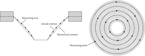
A truncated cone with 25 layers was taken as the research target. The radial accuracy error is shown in Figure 2. The dashed line indicates the theoretical contour of the part, and the solid line is the actual contour. The two contours have geometrical deviations in the radial direction of the truncated cone. The deviation value is the radial accuracy error. This value is obtained by averaging the accuracy errors of the five measuring areas. The measuring areas are equidistantly distributed along the side wall direction. And each area contains five layers of forming trajectories. In order to improve the measurement accuracy, the average of the accuracy of the three measuring points is taken as the accuracy of the area. These measuring points are obtained at equal angles in each area.
2.2. Generation Mechanism of Radial Accuracy Error
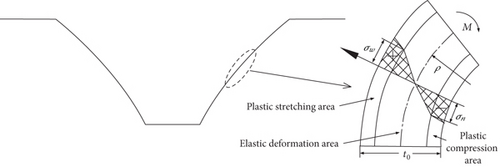
Figure 3 is the stress situation of the part when it generates springback after the tool head and the holding devices are unloaded. The left part is the springback of the entire part. And the right part is the stress situation of a small piece of sheet on the side wall of the left part. The sheet is inward bent, and the section of the part is followed by a plastic stretching area, an elastic deformation area, and a plastic compression area. t0 is the thickness of the part. ρ is the curvature radius of the neutral layer of the part. M is the bending moment. σw is the stress of the plastic stretching area, and σn is the stress of the plastic compression area.
2.3. Response Surface Experiment on Forming Accuracy
The response surface method (RSM) is selected as the research method. Before the ultrasonic vibration is introduced into the forming process, the method is first used to analyze the influence of parameters other than the vibration parameters on the forming radial accuracy. This method not only can obtain the radial accuracy error of the part under different process parameters and the significant degree of each process parameter to the accuracy but also can obtain the mutual coupling influence of process parameter on the radial accuracy error.
2.3.1. Experimental Equipment
The three-axis vertical CNC milling machine was adopted as the SPIF experimental platform. The forming tool was a hemispherical tool head made of X210CrW12 tungsten high-speed steel. Its high rigidity and hardness and wear resistance can effectively guarantee the surface quality of the part and avoid the interference of tool head deformation on the accuracy of the part. Since the feed speed of the tool head has little effect on the forming accuracy, the feed speed was set to 500 mm/min in order to improve the forming efficiency. AL1060 aluminum alloy was used as the forming sheet with a dimension of 140 mm × 140 mm. The truncated cone had a target depth of 25 mm, and L-HM46 was used as the lubricant.
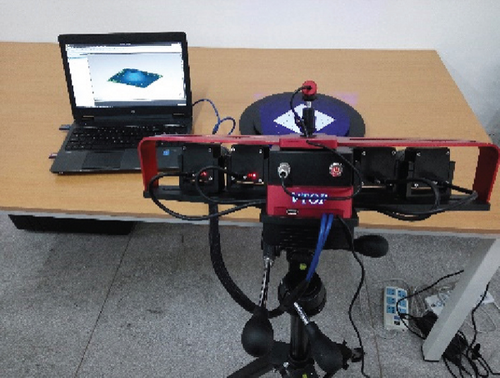
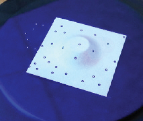
The V-TOP high-accuracy blue light scanner was used as the accuracy measuring equipment, as shown in Figure 4. This device can realize the overall accuracy error analysis and automatic splicing of the part. It has a high scanning precision and a quick scanning speed. It can get accurate point cloud data. The inner and outer surfaces of the part must be sprayed with the developer and attached marking points before scanning. In this way, the scanner can perform multiple scans and data splicing on the geometric appearance of the part. Finally, the exact actual part dimension was obtained, as shown in Figure 5. The actual part dimension was measured using the reverse check software Geomagic Qualify 2013. Then the measured dimensions and design dimensions were visually compared and analyzed.
2.3.2. Experimental Scheme and Measurement Results
It can be known from the past researches that the tool head diameter, the layer spacing, the plate thickness, and the forming angle have a large influence on the radial accuracy [22, 23]. Therefore, the four process parameters were selected to design the BBD experimental scheme with 4 factors and 3 levels. The design factors and levels are shown in Table 1. The experimental scheme and measurement results are shown in Table 2.
| Factors | Levels | Unit | ||
|---|---|---|---|---|
| -1 | 0 | 1 | ||
| A: tool head diameter | 6 | 8 | 10 | mm |
| B: layer spacing | 0.5 | 1 | 1.5 | mm |
| C: sheet thickness | 0.6 | 0.8 | 1 | mm |
| D: forming angle | 45 | 50 | 55 | Degree |
| Number | A (mm) | B (mm) | C (mm) | D (°) | Radial accuracy error (εj/mm) |
|---|---|---|---|---|---|
| 1 | 8.00 | 1.00 | 0.80 | 50.00 | 0.56002 |
| 2 | 8.00 | 1.00 | 1.00 | 55.00 | 0.80323 |
| 3 | 10.00 | 0.50 | 0.80 | 50.00 | 0.97015 |
| 4 | 6.00 | 1.00 | 0.80 | 55.00 | 0.74722 |
| 5 | 10.00 | 1.00 | 0.80 | 45.00 | 0.99506 |
| 6 | 8.00 | 1.50 | 0.80 | 55.00 | 0.83006 |
| 7 | 8.00 | 0.50 | 0.80 | 55.00 | 0.81606 |
| 8 | 8.00 | 0.50 | 0.60 | 50.00 | 0.41306 |
| 9 | 8.00 | 1.50 | 0.60 | 50.00 | 0.59305 |
| 10 | 8.00 | 1.00 | 0.80 | 50.00 | 0.58106 |
| 11 | 6.00 | 1.00 | 0.80 | 45.00 | 0.35906 |
| 12 | 10.00 | 1.00 | 0.80 | 55.00 | 1.19906 |
| 13 | 8.00 | 1.00 | 0.60 | 45.00 | 0.44305 |
| 14 | 6.00 | 1.00 | 1.00 | 50.00 | 0.32906 |
| 15 | 10.00 | 1.00 | 1.00 | 50.00 | 1.19706 |
| 16 | 8.00 | 0.50 | 0.80 | 45.00 | 0.35006 |
| 17 | 6.00 | 0.50 | 0.80 | 50.00 | 0.18406 |
| 18 | 8.00 | 1.50 | 1.00 | 50.00 | 0.65306 |
| 19 | 10.00 | 1.00 | 0.60 | 50.00 | 0.80906 |
| 20 | 8.00 | 1.50 | 0.80 | 45.00 | 0.59606 |
| 21 | 10.00 | 1.50 | 0.80 | 50.00 | 0.80406 |
| 22 | 8.00 | 1.00 | 0.80 | 50.00 | 0.58524 |
| 23 | 8.00 | 0.50 | 1.00 | 50.00 | 0.47305 |
| 24 | 6.00 | 1.50 | 0.80 | 50.00 | 0.74206 |
| 25 | 8.00 | 1.00 | 0.60 | 55.00 | 0.74306 |
| 26 | 8.00 | 1.00 | 0.80 | 50.00 | 0.59306 |
| 27 | 8.00 | 1.00 | 1.00 | 45.00 | 0.50306 |
| 28 | 8.00 | 1.00 | 0.80 | 50.00 | 0.63258 |
| 29 | 6.00 | 1.00 | 0.60 | 50.00 | 0.59706 |
2.4. Ultrasonic Vibration-Assisted Single Point Incremental Forming
Ultrasonic vibratory plastic forming technology is superior to ordinary plastic forming in regard to both difficult-to-form materials and precision forming and is specifically expressed in two aspects: first, it can significantly reduce the yield stress and flow stress; second, it can improve the lubrication effect and change the friction mechanism. Therefore, the ultrasonic vibration plastic forming technology was introduced into the SPIF to change the size and distribution of the residual stress of the part, thereby reducing the springback and improving the accuracy. UV-SPIF is the abbreviation for the technology.
2.4.1. Forming Principle
The technical principle of UV-SPIF is shown in Figure 6. It can be seen that the principle differs from the principle of the SPIF in that the tool head is replaced with an ultrasonic vibration spindle tool. This has led to a change in the contact way between the tool and the sheet, essentially changing the deformation mechanism of the material.
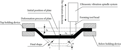
When the tool head is driven by the ultrasonic vibratory spindle, the sheet can be formed along the trajectory by the tool head with ultrasonic vibration. The vibration direction is shown in Figure 6. In this case, the contact state of the tool head and the sheet are not continuous rolling contact under SPIF, but instead high-frequency impact point pressure contact under UV-SPIF. In addition, compared to SPIF, the contact type, stress condition, lubrication state, and plastic flow law of the metal are changed. Behind these changes is the change in the size and distribution of the residual stress, which in turn affects the accuracy of the formed part.
2.4.2. Experimental Equipment
The Qinchuan MVC510 vertical CNC machine tool was used as the experimental platform to build the experimental device. The experimental process is shown in Figure 7. The spindle system and the sheet clamping system were designed and developed.
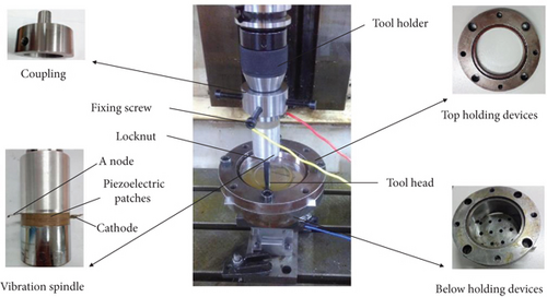
The spindle system consisted of a tool holder, a coupling, and a vibration spindle. The connection between the vibration spindle and the tool holder was realized through the coupling. And the connection between the coupling and the vibration spindle was achieved by four fixing screws. The vibration spindle was composed of a transducer, amplitude transformer, and spindle shell. The transducer and amplitude transformer were mounted inside the spindle shell as internal components. The anode and cathode of the vibration spindle were connected to the ultrasonic generator through wires. A stepless frequency modulation ultrasonic generator was selected as the vibration generator. The vibratory frequency of the generator is continuously adjustable from 13 kHz to 75 kHz, and the adjustment is accurate to 0.1 kHz.
The sheet holding system consists of top holding devices and below holding devices, and the two were bolted to tighten the sheet. In addition, in order to prevent the tool head from loosening due to vibration and affecting the forming accuracy, the tool head was pretensioned by a locknut.
3. Results and Discussion
3.1. Response Surface Results and Analysis
The relationship between the process parameters and the radial accuracy error was studied by analysis of variance (ANOVA). The analysis results are shown in Table 3. It can be seen that the P value of the model is less than 0.05. This means that the established second-order model of radial accuracy is reliable and efficient. And the F value of the lack of fit is 2.95, and its P value is greater than 0.05, so the lack of fit is not significant. This means that the relationship between radial accuracy and process parameters can be better analyzed and predicted by this model. In addition, the fitting coefficient R2 of this model is 0.9857. The closer the value is to 1, the higher the predictive power of the model. The signal-to-noise ratio accuracy is 33.849, which is greater than 4. It further illustrates the adaptability of the model.
| Source | SS | df | MS | F value | P value |
|---|---|---|---|---|---|
| Model | 1.63 | 14 | 0.12 | 69.12 | <0.0001 |
| A | 0.76 | 1 | 0.76 | 449.50 | <0.0001 |
| B | 0.085 | 1 | 0.085 | 50.60 | <0.0001 |
| C | 0.011 | 1 | 0.011 | 6.41 | 0.0239 |
| D | 0.30 | 1 | 0.30 | 176.96 | <0.0001 |
| A2 | 0.14 | 1 | 0.14 | 84.84 | <0.0001 |
| B2 | 0.010 | 1 | 0.010 | 6.16 | 0.0264 |
| C2 | 3.582 × 10⁻³ | 1 | 3.582 × 10⁻³ | 2.12 | 0.1671 |
| D2 | 0.042 | 1 | 0.042 | 24.63 | 0.0002 |
| AB | 0.13 | 1 | 0.13 | 77.73 | <0.0001 |
| AC | 0.11 | 1 | 0.11 | 63.80 | <0.0001 |
| AD | 8.479 × 10⁻³ | 1 | 8.479 × 10⁻³ | 5.03 | 0.0417 |
| BC | 1.000 × 10⁻¹⁰ | 1 | 1.0000 × 10⁻¹⁰ | 5.9300 × 10⁻⁸ | 0.9998 |
| BD | 0.013 | 1 | 0.013 | 7.98 | 0.0135 |
| CD | 6.400 × 10⁻⁹ | 1 | 6.4000 × 10⁻⁹ | 3.7950 × 10⁻⁶ | 0.9985 |
| Residual | 0.024 | 14 | 1.686 × 10⁻³ | — | — |
| Lack of fit | 0.021 | 10 | 2.079 × 10⁻³ | 2.95 | 0.1547 |
| Pure error | 2.823 × 10⁻³ | 4 | 7.058 × 10⁻⁴ | — | — |
| Cor total | 1.66 | 28 | — | — | — |
| Std. dev. | 0.041 | — | — | R2 | 0.9857 |
| Mean | 0.66 | — | — | Adj R2 | 0.9715 |
| C.V.% | 6.23 | — | — | Pred R2 | 0.9250 |
| PRESS | 0.12 | — | — | Adeq precision | 33.849 |
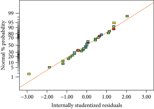
Figure 8 is a normal distribution diagram of the radial accuracy regression model. The distribution of the points is similar to a straight line, indicating that the data is reliable without major deviation. This proves the credibility of this variance analysis and the validity of the regression model.
The coupling effects of various factors were analyzed using Minitab’s DOE tool, as shown in Figures 9(a)–9(f). The results of these analyses were based on the other two factors at zero level. Figures 9(a)–9(c) are response surface diagrams of the radial accuracy error under the coupling of the tool head diameter and the layer spacing, the plate thickness, and the forming angle. It can be seen that as the diameter of the tool head increases, the radial accuracy error also increases. This is because increasing the diameter of the tool head is equivalent to increasing the amount of deformation. The higher amount of deformation causes the sheet to produce a greater springback, resulting in an increase in radial accuracy error. However, when the layer spacing is large and the sheet thickness is small and the forming angle is large, the radial error increases slowly as the tool head diameter increases. In Figure 9(a), when the layer spacing is increased to 1.5 mm, the tool head diameter is no longer the first factor affecting radial accuracy. Therefore, its effect on radial accuracy is no longer significant. In Figure 9(b), when the sheet thickness is less than 0.75 mm, the springback of the part is reduced. The deformation caused by the tool head with a diameter of 9 mm or less is mainly plastic, so the influence of the tool head on the radial error is not significant. In Figure 9(c), when the forming angle is increased, this is equivalent to the horizontal feed remaining unchanged, increasing the radial feed, that is, increasing the layer spacing. The mechanism is the same as the analysis in Figure 9(a).
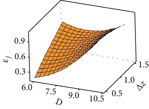
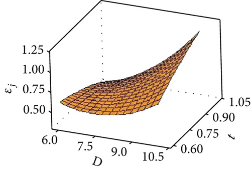

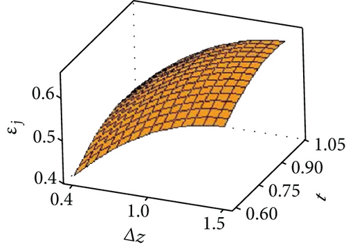
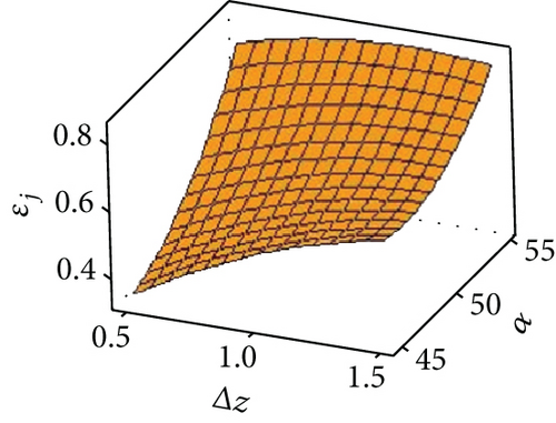
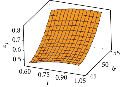
Figures 9(d) and 9(e) are the response surface diagrams of the radial accuracy error under the coupling of the layer spacing, plate thickness, and forming angle. Figure 9(f) is a response surface diagram of the radial accuracy error under the coupling of the sheet thickness and the forming angle. It can be seen from Figures 9(d) and 9(f) that the mutual coupling of the factors in the two groups of plate thickness and layer spacing and plate thickness and forming angle is small. Different sheet thicknesses do not interact for different layer spacings and forming angles. The radial accuracy error of the part increases as the layer spacing and forming angle increase. It can be seen from Figure 9(e) that there is an interaction between the layer spacing and the forming angle. This is because the size of the forming angle is determined by the layer spacing and the horizontal feed.
3.2. Experimental Results and Analysis of UV-SPIF
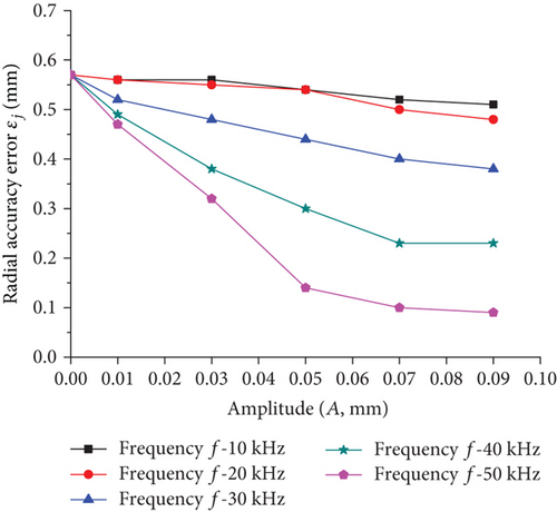
To quantitatively study the influence of the frequency and amplitude on the radial accuracy, a stepless frequency modulation ultrasonic generator was selected as the vibration generator. Experiments have been conducted to measure its longitudinal amplitude. The results show that when the power of the ultrasonic generator are 246 W, 606 W, 1203 W, 1795 W, and 2234 W, the corresponding amplitudes are10 μm, 30 μm, 50 μm, 70 μm, and 90 μm [24]. The influence of vibration parameters on the accuracy was studied experimentally when the tool head diameter was 8 mm, the layer spacing was 1 mm, the sheet thickness was 0.8 mm, and the forming angle was 50°.
Figure 10 shows the effect of frequency on radial accuracy error under different amplitude conditions. It can be seen that the radial accuracy error decreases as the frequency increases. However, when the frequency is in the range of 10 kHz~30 kHz, the frequency has little effect on the accuracy. When the frequency exceeds 30 kHz, the accuracy error is drastically reduced. This is because the vibrational energy causes the material to have a softening effect, so that the residual stress is greatly reduced. It can be seen from the slope of the curve that when the amplitude is large, the higher the frequency, the more significant the material softening effect.
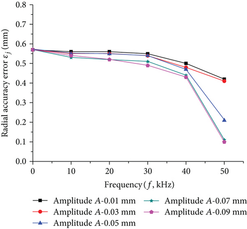
Figure 11 shows the effect of amplitude on radial accuracy error under different frequency conditions. It can be seen that the radial accuracy error also decreases as the amplitude increases. When the frequency is small, the effect of amplitude on the accuracy error is not significant. This is because the vibration energy is not sufficient to cause a softening effect on the material. The effect of increasing the amplitude at this time is only equivalent to slightly increasing the layer spacing. Once the frequency exceeds 30 kHz, the change in amplitude will have a significant softening effect on the material. It can be seen that in order to improve the accuracy of the part by amplitude, it is necessary to increase the frequency above 30 kHz.
4. Conclusion
- (1)
The radial accuracy error of the part comes from the residual stress inside the material after the tool head and the holding device are unloaded. After unloading, the tensile stress and compressive stress are, respectively, exhibited on both sides of the sheet. These two stresses interact with the elastic layer inside the material to cause the sheet to produce a bending springback with a bending moment of M
- (2)
Tool head diameter, layer spacing, sheet thickness, and wall angle all have a certain interaction when affecting the radial accuracy error. An increase in process parameters generally results in an increase in the amount of deformation of the sheet. Therefore, the accuracy error generally increases as the process parameters increase
- (3)
The technology of VU-SPIF can effectively reduce the accuracy error value and improve the forming quality of the part. This is because the vibrational energy causes the material to have a softening effect, so that the residual stress is greatly reduced. In addition, to increase the accuracy by the amplitude, the frequency must be increased to 30 kHz or more
Conflicts of Interest
The authors declare that they have no conflicts of interest.
Acknowledgments
The authors would like to acknowledge the National Natural Science Foundation of China (Grant Nos. 51475366 and 51805433) and the Science & Technology Planning Project of Shaanxi Province (Grant No. 2016JM5074).
Open Research
Data Availability
The data used to support the findings of this study are available from the corresponding author upon request.


