Three-Dimensional Impact Time and Angle Control Guidance Based on MPSP
Abstract
A new nonlinear guidance law for air-to-ground missile cooperation attacks is proposed in this paper. This guidance law enables missiles with different initial conditions to attack targets simultaneously, and it can also precisely satisfy the terminal impact angle conditions in both flight-path angle and heading angle. The guidance law is devised using the model predictive static programming (MPSP) method, and the control saturation constraint is incorporated in the MPSP algorithm. The first-order-lag acceleration of the missile is taken as the state variable to realize the convergence of the terminal acceleration to zero. Moreover, a collision avoidance strategy for three-dimensional missile cooperative flight is proposed. The simulation results show that the guidance law can make the missiles hit the target accurately at the same time with the ideal impact angles and can realize the control saturation constraints of the missiles. This can increase the attack effects and is significant for collaborative attacks.
1. Introduction
When a missile strikes a target, its damage to the target can increase at a particular attack angle. For example, in the applications of anti-tank missiles, it is best to use the top attack, because the top of the tank is usually the weakest. Similarly, when anti-ship missiles attack ships, the right attack angle can increase the attack effects. In these cases, the missile’s terminal flight-path angle and heading angle will usually be specified. The impact time is another important aspect of improving the missile effectiveness, especially for cooperation attacks, where missiles should hit the target simultaneously. There are many self-defense measures against anti-ship missiles in modern warfare ships, such as surface-to-air missiles, ECM systems, and CIWS (close-in weapon system). It is difficult to hit a ship through these defense systems. However, CIWS has one-by-one engagement characteristics, so salvo attack is an effective way to solve this problem, in which several missiles strike the target simultaneously. In conclusion, it is necessary to control the impact time and angle to make this cooperation attack mission successful.
There are many published articles on impact angle control. In [1], Ryoo et al. studied the closed solution of optimal guidance laws to control the impact angle and terminal instability and presented a generalized form of optimal impact-angle control guidance laws. To realize the impact angle constraint on the still target, Jeong et al. presented a new biased proportional navigation guidance law in [2]. Lu et al. established the closed-loop nonlinear adaptive control law to realize the terminal impact angle control and applied it to the terminal guidance of the hypersonic glider in [3]. In [4], Xu et al. presented a missile integrated guidance scheme with impact angle constraint based on the idea of reverse propulsion and VSC theory. In [5], Pamadi and Ohlmeyer proposed two different guidance laws to achieve impact angle control. The first one is a trajectory shaping control law GENEX, and the second one, FITS, is a predictive guidance method. In [6], Sang et al. proposed a guidance law that minimizes miss distance and satisfies impact angle constraint. This method is based on Lyapunov stability theory and applied parameter optimization. In [7], using model predictive static programming (MPSP), Oza and Padhi proposed a guidance law that can satisfy terminal impact angle constraints accurately. In [8], Zhang et al. introduced a two-phased look angle control guidance scheme with the terminal impact angle constraints.
In recent years, there have been more and more articles on impact time control. In [9], Jeon et al. combined the proportional navigation guidance law and the feedback of the impact time error to achieve the impact time control. In [10], Shiyu and Rui proposed a collaborative guidance method combining coordination algorithm and local guidance law, and the impact-time-control guidance law obtained in [9] was used. In [11], Zhang et al. designed a steady impact-time-control guidance law for multi-missiles. A guidance law based on sliding mode control, which enables a missile to hit a stationary target at a given impact time, was proposed by Kumar and Ghose in [12]. Besides, there are other articles on impact time control, [13, 14].
However, only a few papers have been written on the guidance laws for controlling impact time and impact angle simultaneously. In [15], Zhang et al. propose a guidance law controlling both impact angle and impact time. This guidance law is a combination of biased proportional navigation guidance (BPNG) and an additional command for the impact time. A new impact time and angle control guidance law based on sliding mode was proposed by Harl and Balakrishnan in [16]. In [17], to get a state feedback command with terminal constraints of impact time and angle, Kim et al. introduced a polynomial function, which has three unknown coefficients. In [18], to make full use of the vulnerability of warships, Kang and Kim proposed a linear quadratic differential game guidance law to make the impact angle and time of the missile controllable. A collaborative attack guidance law which can control impact time and angle based on sliding mode control was proposed by Yang et al. in [19]. In [20], Harrison proposed a new method to derive the optimal missile guidance law and proposed a three-dimensional hybrid guidance law that constrains the impact angle and time. Kumar and Ghose proposed a guidance strategy based on impact angle control to meet the impact time constraint in [21].
Nevertheless, most of the existing articles consider the two-dimensional case. There are few articles that consider both impact time control and terminal impact angle constraints at the three-dimensional level.
- (1)
The control saturation constraint is considered in the MPSP algorithm, the specific derivation process is given, and the effectiveness of the algorithm is verified by simulation
- (2)
A collision avoidance strategy for three-dimensional missile cooperative flight is derived, and its effectiveness is verified
- (3)
The proposed guidance law achieves three-dimensional impact time and angle control simultaneously, and it is an effective means of cooperation attack. The utility of MPSP in impact time and angle control problem can be confirmed
- (4)
By treating the first-order-lag acceleration commands as state variables, the terminal acceleration command converges to zero, which is beneficial to reduce the miss distance caused by random interference
This paper is arranged as follows. The mathematical model and presentation of the problem is described in Section 2. The MPSP theory is described in Section 3. The implementation of the algorithm is described in Section 4, and the numerical simulations are provided in Section 5. Finally, Section 6 gives the conclusion.
2. Problem Statement
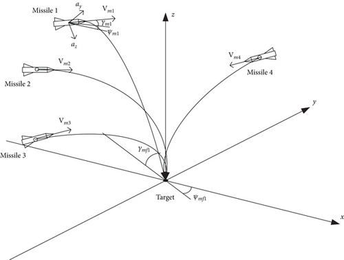
As shown in Figure 1, consider a scenario of a three-dimensional multi-missile coordinated attack. Several air-to-ground missiles are launched from different directions and positions, and the target can be considered stationary. The missiles need to attack the target simultaneously at tf time, and each missile needs to reach its required impact angle γmfi and ψmfi.
| Parameters | |
|---|---|
| PN guidance constant, N | 4 |
| Normalizing velocity | 600 m/s |
| Normalizing angle, (γ∗, ψ∗) | (50 deg, 50 deg) |
| Normalizing coordinates, (x∗, y∗, z∗) | (5 km, 5 km, 5 km) |
| Normalizing acceleration | g = 9.81 m/s2 |
| Autopilot first-order lag, τ | 0.3 s |
| Mass of missile | 150 kg |
| Thrust force, T | 0 N |
| Surface area, sm | 0.0324 m2 |
The mission objective is that all missiles hit the target at a same terminal time tf. Besides, missiles should have a specific terminal impact angle. Here, the control variable is defined as . The terminal constraints can be written as .
3. Model Predictive Static Programming (MPSP) with Control Saturation Constraints
In this section, we introduce the formula derivation of the model prediction static programming (MPSP) [22] algorithm, which can solve the two-point boundary value problem. In addition, the control saturation constraints, namely, input inequality constraints, are considered in the algorithm.
The MPSP algorithm starts with initial control guesses. In general, initial control guesses cannot satisfy terminal constraints. Therefore, the control history can be updated with a dynamic error. Iteration is kept until .
The new control variables can be calculated by Eq. (30) and Eq. (31). We research the impact time and angle control problem based on this technology.
4. Implementation of the Guidance Law
4.1. Terminal Impact Time and Guess History Selection
To achieve the cooperation attack, we need to choose a same impact time of missiles. We use the PN guidance law to calculate each missile’s impact time then choose the maximum as the impact time for all missiles. The PN guidance law is briefly introduced here.
Now, we have the common impact time tf. First, let all missiles attack the target at impact time tf without impact angle constraint, and select zero as the guess history. Then, the result without impact angle constraint can be regarded as the guess history with impact angle constraint.
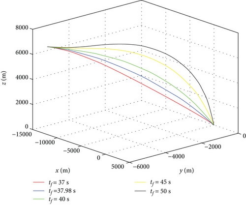
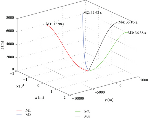
Then, we analyze the feasibility of the selected final impact time. According to the simulation conditions in Section 5, missile 1 is taken as an example for analysis. Guided by the PN guidance law, missile 1 flies 37.98 s to hit the target, which has the longest flight time of the four missiles. The lateral acceleration of the missile is the control, which can make the trajectory straighter or more curved. The more curved the trajectory is, the longer the flight distance of the missile will be and the longer the flight time will be. Similarly, the straighter the trajectory, the shorter the flight time. However, the trajectory can only be straightened limitedly, but theoretically it can be bent indefinitely. In fact, there is aerodynamic drag, so the flight time can only be increased in a limited range. Even so, the missile’s ability to increase flight time is significantly stronger than that to reduce flight time. Figure 2 shows the trajectories of missile 1 with flight times of 37 s, 37.98 s, 40 s, 45 s, and 50 s, respectively, from which we can draw the same conclusion. For missile 1, it is obviously reasonable to choose a final time of 37.98 s, and for missiles 2, 3, and 4, 37.98 s is a larger final time, which is also reasonable. In conclusion, it is feasible to select the maximum impact time as the final impact time of all missiles.
4.2. Collision Avoidance Strategy
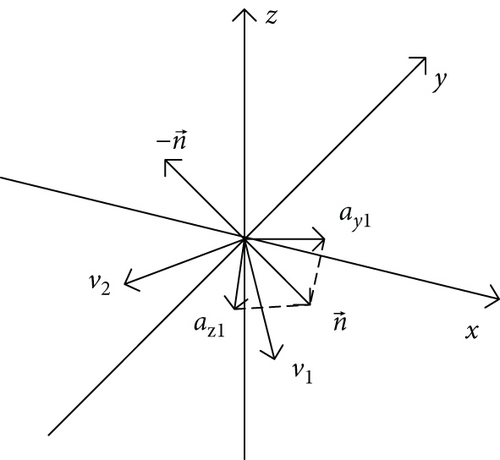
To avoid the collision of missiles in flight, we deduce a collision avoidance strategy. The following is a detailed derivation process.
To verify the effectiveness of the collision avoidance strategy, we design a collision situation and then use the collision avoidance strategy to simulate it. The results are shown in Figure 4.
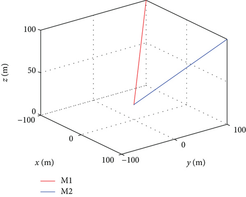
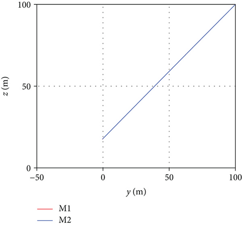
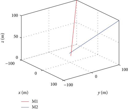
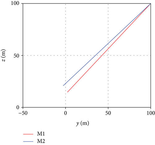
In Figure 4, the above two pictures are the situations without collision avoidance, while the following two pictures are the situations with collision avoidance. It can be seen that the proposed collision avoidance strategy is effective.
When there is a risk of collision between multiple missiles, the direction vector of the acceleration of each missile’s anti-collision command is obtained firstly, which is the vector sum of the acceleration vectors of the anti-collision command produced by this missile with all other missiles. Finally, the acceleration vector is decomposed into az and ay directions of the missile. Thus, the collision avoidance command acceleration of each missile is obtained.
It should be noted that the missile will eventually hit the target at the same time; that is to say, the distance between the missiles in the final stage will certainly be less than the set threshold Rm. Therefore, collision avoidance judgment is not carried out in the whole flight process. When the distance between the missile and the target rmt is less than a certain preset value Rt(Rt > Rm), collision avoidance judgment is no longer carried out. In this study, we chose Rm = 200(m) and Rt = 1000(m). In the final flight stage without collision avoidance judgment, we set different terminal angles of each missile to ensure that the missiles would not collide before hitting the target.
4.3. Guidance Law Implementation
- (1)
Use the PN guidance law to obtain impact time tf of missiles
- (2)
Guess the initial control history. It is zero without impact angle constraint. In the case of with impact angle constraint, the guess history is the result of without impact angle constraint
- (3)
Use the RK4 method to simulate system dynamics for the given guess history, and the collision avoidance strategy is added to the simulation
- (4)
Compute Bk, k = N − 1, …, 1, matrices using Eq. (13)
- (5)
Compute Aλ and Bλ, then compute new control Un using Eq. (30) or (31)
- (6)
Go to step 3 until the algorithm converges
5. Numerical Simulations
In this section, simulation results are given to show the effectiveness of the proposed guidance law in cooperation attacks. We first present the simulation results of the PN guidance law. Then we consider two cases, only impact time control and impact time and angle control, without considering the control saturation. Finally, the simulation results considering the control saturation are given. Table 1 lists the other simulation parameters and the parameters used by the PN guidance law (drag parameters; see Imado et al. [25]). In this paper, we present a simulation study of four missiles attacking the stationary target. The initial conditions of the simulation are shown in Table 2.
| V (m/s) | γ (°) | ψ (°) | (x, y, z) (km) | (az, ay) (m/s2) | |
|---|---|---|---|---|---|
| Missile 1 | 578 | 0 | 10 | (-12, -6, 7) | (0, 0) |
| Missile 2 | 578 | -5 | -20 | (-11.5, 2, 7.5) | (0, 0) |
| Missile 3 | 578 | 0 | -170 | (12, 5, 6) | (0, 0) |
| Missile 4 | 578 | -10 | -150 | (12, 3, 8) | (0, 0) |
| Target | 0 | \ | \ | (0, 0, 0) | \ |
5.1. Result of the PN Guidance Law and the Choice of Impact Time
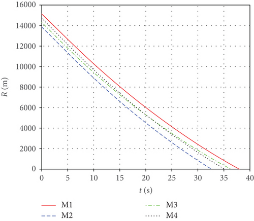
In this subsection, the PN guidance law is used for simulation and the results are presented. The time step Δt = 0.01 s, and the initial conditions are shown in Table 2. Simulation results are shown in Figures 5 and 6. Figure 5 shows the cooperation attack trajectories of the four missiles under different initial conditions, from which it can be seen that the attack time of each missile is quite different. The missiles hit the target at 37.98 s, 32.62 s, 35.16 s, and 36.38 s, respectively. We chose the maximum impact time 37.98 s as the terminal impact time tf for all missiles, which is used in the MPSP algorithm. Figure 6 shows the relative distances between missiles and the target. We can see that the PN guidance law does not have the ability to make missiles hit the target at the same time.
5.2. Case with Impact Time Constraint
This subsection gives the simulation results for impact time control. The initial conditions are shown in Table 2, and the terminal constraints are shown in Table 3. We choose the time step Δt = 0.01 s, and the weighting matrix Rk = 1, k = 1, 2, …N − 1. The convergence criterion for this simulation study is a miss distance of 1 m, and acceleration tolerance error is 1 m/s2.
| tf (s) | V (m/s) | γ (°) | ψ (°) | (x, y, z) (km) | (az, ay) (m/s2) | |
|---|---|---|---|---|---|---|
| Missile 1 | 37.98 | / | / | / | (0, 0, 0) | (0, 0) |
| Missile 2 | 37.98 | / | / | / | (0, 0, 0) | (0, 0) |
| Missile 3 | 37.98 | / | / | / | (0, 0, 0) | (0, 0) |
| Missile 4 | 37.98 | / | / | / | (0, 0, 0) | (0, 0) |
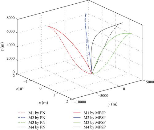
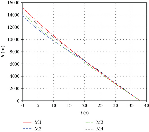
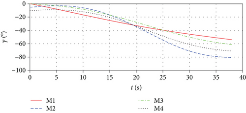
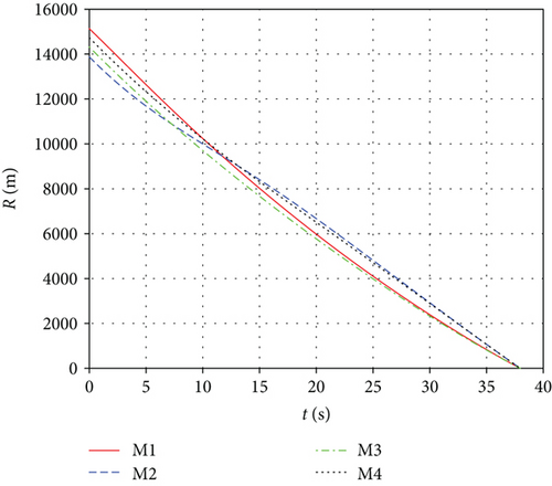
Figure 7 shows the missile trajectories with impact time control by MPSP guidance. Figure 8 shows the relative distances between missiles and the target. From Figures 7 and 8, it can be observed that although the initial conditions of the missiles are different, the missiles can hit the target at the specified impact time 37.98 s simultaneously. Figure 9 presents the histories for the flight path angles γ and heading angles ψ, only with impact time constraint. The terminal angle is not controlled because there is terminal impact angle constraint. Figure 10 shows the histories of missiles’ first-order-lag lateral acceleration. We can see that the lateral acceleration converges to zero at the terminal time, which can increase the anti-interference ability of missiles and is beneficial to reduce the miss distance caused by random interference. In addition, the control histories are used as guess histories in the case of with impact time and angle constraints.
5.3. Case with Impact Time and Angle Constraint
In this subsection, results for impact time and angle control are presented. As we mention in Section 1, good impact angles will enhance the effect of a cooperation attack. Now, we let the missiles attack the stationary target and constrain the impact time and angle; terminal constraints and initial conditions are shown in Tables 4 and 2, respectively. The target is assumed to face -40 degrees. In this condition, one missile strikes vertically, one strikes from the front at a -60-degree flight path angle, and the other two can strike horizontally from both sides. When the flight path angle is -90 deg, it makes no sense to constrain the heading angle, which is why the heading angle is not restricted under such circumstances. The time step Δt = 0.01 s. We want to have a lower acceleration in the later stage; therefore, we chose the control weighting matrix as , k = 1, 2, …N − 1. The convergence criterion for this simulation study is a miss distance of 1 m, 10−3deg allowable error in angle, and 1 m/s2 allowable error in acceleration.
| tf (s) | V (m/s) | γ (°) | ψ (°) | (x, y, z) (km) | (az, ay) (m/s2) | |
|---|---|---|---|---|---|---|
| Missile 1 | 37.98 | / | 0 | 50 | (0, 0, 0) | (0, 0) |
| Missile 2 | 37.98 | / | -60 | -40 | (0, 0, 0) | (0, 0) |
| Missile 3 | 37.98 | / | 0 | -130 | (0, 0, 0) | (0, 0) |
| Missile 4 | 37.98 | / | -90 | / | (0, 0, 0) | (0, 0) |
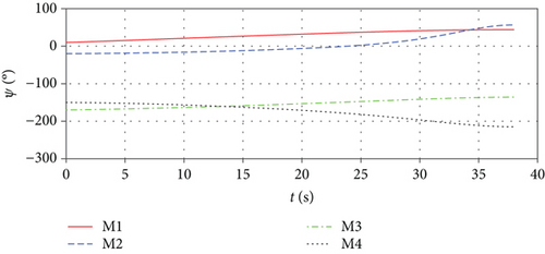
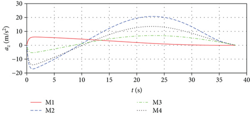
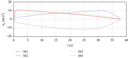
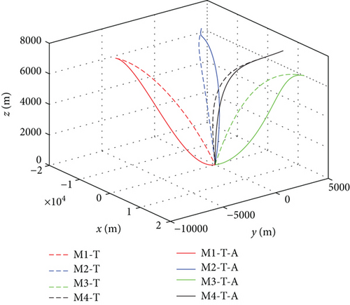
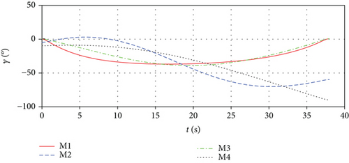
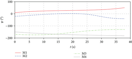
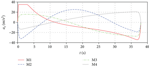
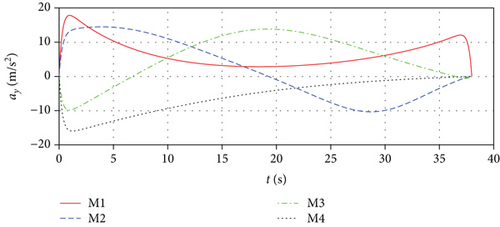
Figure 11 shows the missile trajectories with impact time and angle control by MPSP guidance; Mi-T i = 1, 2, 3, 4 means missile trajectories with impact time control, and Mi-T-A i = 1, 2, 3, 4 means missile trajectories with impact time and angle control. Figure 12 shows the relative distances between missiles and the target. Figure 13 presents the histories for the flight path angles γ and heading angles ψ with impact time and angle control. We can observe that the impact angles converge to the desired values at the expected impact time 37.98 s, which verifies the validity of the proposed guidance law. Because both the initial and final flight path angles of missiles 1 and 3 are zero, the missile acceleration az is larger at the beginning and end than at the middle, as shown in Figure 14. But we can still get the final acceleration to zero by constraining the terminal acceleration, which is beneficial to reduce the miss distance caused by random interference.
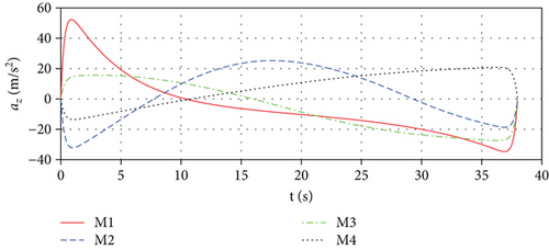

During an attack, the missile’s acceleration is generally limited; hence, we need to verify the effectiveness of the algorithm when the acceleration exceeds the boundary. Of course, the acceleration is over the boundary for a period of time, not all of the time. We chose the acceleration limit as 35 m/s2, which may be greater in a real situation. The histories of missiles’ lateral acceleration are shown in Figure 15, and the algorithm still converges. The missile can still strike the target accurately at the required impact time and angle. Comparing Figure 15 with Figure 14, we can find that when the acceleration exceeds the limit, the entire acceleration is adjusted to accommodate the new situation. We can see that the algorithm is effective when the acceleration exceeds the boundary.
6. Conclusions
In this paper, a new guidance law for air-to-ground missile cooperation attacks is presented based on the MPSP technique, which can simultaneously constrain the impact time and angle. The main feature of this guidance is the ability to guide missiles with different initial conditions to attack the target at the same time at a specific flight path angle and heading angle. Control saturation restrictions are considered in the MPSP algorithm, which widens the application scope of the MPSP algorithm. Moreover, by taking the first-order-lag acceleration as a state variable, the missile acceleration converges to zero at the end, which can increase the anti-interference ability of missiles and is beneficial to reduce the miss distance caused by random interference. In this paper, a collision avoidance strategy applied to three-dimensional missile cooperative guidance flight is proposed, which can successfully avoid missile collision. It can be seen from the simulation results that the guidance law can successfully complete the cooperation attack.
Conflicts of Interest
The authors declare that there is no conflict of interests regarding the publication of this paper.
Acknowledgments
This work is supported by Aeronautical Science Foundation of China (no. 20150151002).
Open Research
Data Availability
The data used to support the findings of this study are included within the article.


