Fast Attitude Maneuver of a Flexible Spacecraft with Passive Vibration Control Using Shunted Piezoelectric Transducers
Abstract
This paper is concerned with designing a bang-bang control input to perform a quick rotational maneuver of a rigid spacecraft hub connected with flexible appendages. The control design is based on only the rigid body mode making it very simple to design and at the same time achieve the quickest maneuver possible. The induced vibrations are suppressed using piezoelectric transducers bonded to the appendages and connected to an electric circuit with the objective of converting the vibrational energy to electrical energy and then dissipating it using passive electric elements, such as a resistance and an inductor. The proposed control design method is applied to a spacecraft containing a rigid hub and flexible appendages. The attitude control torque is produced using either the reaction wheels contained inside the rigid hub or jet thrusters mounted outside it. The control design process starts with deriving the nonlinear partial differential equations of motion for the spacecraft using Hamilton’s principle which accounts for the electromechanical coupling and the presence of resistive or resistive-inductive circuits. To simplify the analysis, the nonlinear ordinary differential equations of motion are then obtained using the assumed mode method. The effectiveness of the control design method is numerically tested on a spacecraft that is required to perform a quick attitude maneuver and, simultaneously, suppress the induced vibrations. The simulations show a quick and accurate maneuver has been achieved combined with very low levels of vibrations resulting from the reduced coupling between flexible and rigid motions as well as the damping added as a result of the passive shunt circuit. Furthermore, the resistance-inductance shunt circuit is shown to be more effective in damping the vibrations than the resistance shunt circuit.
1. Introduction
In recent years, there has been a considerable interest in modelling and control of flexible spacecrafts. This is due to the use of lightweight materials for the purposes of speed and fuel efficiency. Furthermore, these spacecrafts are required to maneuver as quickly as possible without significant structural vibrations during and/or after a maneuver.
Many researchers have used active control techniques to design controllers for both the attitude maneuver as well as the vibration suppression of flexible spacecrafts. Bang and Oh [1] have designed nonlinear predictive controller as well as robust output feedback for the attitude maneuver and vibration suppression of a flexible spacecraft. Their principal idea is to establish a reference trajectory and design a feedback control law which forces the system output variables to follow that trajectory. Yan and Wu [2] have achieved high-precision attitude stabilization for the flexible spacecraft in the presence of disturbances, including vibrations, by combining extended disturbance observer (EDO) with a backstepping feedback controller. The EDO observer is used to estimate the space environmental disturbances, unmodeled dynamics, and the disturbances caused by the elastic vibrations of flexible appendages. The design of an adaptive output feedback control law for the rotational maneuver and vibration suppression of a flexible spacecraft, with a model that includes unstructured uncertainties, is proposed by Singh and Zhang [3]. Okubo and Kuwamoto [4] have addressed the issue of agile attitude maneuver control of flexible spacecraft using control moment gyroscopes. The attitude maneuver as well as the induced vibration suppression is achieved using an integrated feedback/feedforward control law. The development of feedforward and feedback control strategies for active vibration suppression and attitude control of a flexible spacecraft using modified component synthesis vibration suppression (CSVS) method has been proposed by Hu et al. [5]. A robust output feedback controller to solve the attitude tracking control problem of a flexible spacecraft in the presence of disturbances is considered by Ye and Xiao [6]. Liu et al. [7] have presented an improved mixed H2/H∞ control technique combined with pole assignment theory to achieve attitude stabilization and vibration suppression, simultaneously, for a flexible spacecraft. An output feedback control law based on Lyapunov stability theory to achieve both attitude as well as vibration control of a highly flexible spacecraft has been proposed by Bang et al. [8].
Other researchers have utilized piezoelectric materials as both sensors and/or actuators in an active manner to suppress the vibrations during spacecraft attitude maneuver. One of the advantages of using piezoelectric materials in a control system is the little added mass and the relatively high control authority. Hu and Friswell [9] have developed a control system for rotational maneuver and vibration suppression of a flexible spacecraft that is based on sliding control method for attitude maneuver and voltage feedback control utilizing piezoceramics for vibration suppression. In a similar manner, Hu and Ma [10] have approached the problem of attitude control and vibration suppression using two separate control loops. The first loop applies optimal sliding mode (OSM) control for the attitude maneuver while the second loop uses positive position feedback (PPF) compensator along with piezoceramics as sensors and actuators to add damping in certain critical flexible modes to suppress the vibrations. In other articles, Hu and Ma [11, 12] have addressed the problem of attitude and vibration controls of a flexible spacecraft separately. The attitude controller is designed using variable structure output feedback control while the vibration suppression control acting on the flexible panels is achieved using piezoceramics as sensors and actuators. Song and Agrawal [13] have solved the problem of vibration reduction of flexible spacecraft during attitude maneuver by using pulse width pulse frequency (PWPF) modulator for thruster firing and smart materials as sensors and actuators employing positive position feedback (PPF) for active vibration suppression. They verified the effectiveness of both control methods experimentally.
In all the preceding articles, the researchers have employed active control techniques to achieve both the attitude control as well as the vibration suppression tasks. The disadvantage of using active control methods including piezoelectric materials as sensors and actuators is the additional hardware required. For example, piezoelectric actuators require high voltage amplifiers for their operations in addition to the control processing units.
Many researchers have also applied optimal control theory to design controllers that can be used to perform a spacecraft large angle maneuver that minimizes a specified objective function. The objective function may include the maneuver final time, maneuver energy consumption, and/or state variables in order to achieve quick maneuver, efficient maneuver, and/or vibration suppression. Turner and Junkins [14] have solved a two-point boundary-value problem to find the solution for the optimal single-axis reorientations of flexible vehicle with minimum torque history and state variables. The time-optimal, single-axis, rest-to-rest rotational maneuver of an elastic spacecraft has been considered by Singh et al. [15]. They used a linear, elastic, undamped, nongyroscopic system model and designed a bang-bang control input having a number of control switches that depends on the number of flexible modes included in the model. Singh and Vadali [16] have presented the design of nonrobust and robust time-optimal controllers for linear flexible systems using the frequency domain. The bang-bang control input is generated from the output of a time-delay filter subject to a step input. Then, the control switching and final times are calculated from a parameter optimization problem that minimizes the final maneuver time and subject to the constraints that the time-delay filter cancels all of the poles of the system.
In all of the previous articles, although the solutions resulting from the optimal control problems are exact, the calculations involved to reach such solutions are tedious and takes a lot of time to calculate.
In this paper, a flexible spacecraft is considered with the objective of performing a quick maneuver while, simultaneously, suppressing the vibrations through shunted piezoelectric transducers connected to passive elements, i.e., a resistance and an inductance. The quick maneuver is achieved by applying torque on the spacecraft rigid body created by either reaction thrusters or motor connected to reaction wheels. The torque time function is designed based on only the rigid body mode alone. The main advantage of considering the rigid body mode alone for the attitude maneuver is to execute the maneuver in the least time possible compared to that when the flexible modes are included. Furthermore, the control torque has a bang-bang (on-off) profile that can be characterized by only one switching time and a final time, where an analytical solution for the values of these times do exist in the literature [17]. The induced vibrations resulting from neglecting the flexible modes in the control design are dissipated in the shunted piezoelectric transducers which are also connected to electric circuit containing a resistor and/or an inductor. This strategy is based on the characteristic of piezoelectric materials to convert mechanical energy to electrical energy which are then transferred and dissipated partially in the electric circuit.
The rest of the paper is organized as follows: Section 2 presents the derivation of the equations of motion for a flexible spacecraft with attached piezoelectric transducers and shunt circuit in the form of nonlinear partial differential equations with natural and boundary conditions based on Hamilton’s principle. These equations are then transformed to nonlinear ordinary differential equations using the assumed mode method. The system model is then transformed into first-order nonlinear time-invariant state-space format in Section 3. Two types of electric circuits are considered in this paper. They are the resonant circuit with resistance and inductance elements and resistive circuit with only resistance element. The calculations for the optimal values of the electric circuit elements, i.e., resistance and inductance for both circuits that results in the maximum energy dissipation, are shown in Section 4. The design of the time-optimal control input torque created by either the jet thrusters or reaction wheel are laid out in Section 5 using either open-loop or closed-loop control torque inputs as well as proportional-derivative control for comparison. Section 6 presents the numerical simulations resulting from the integration of the nonlinear equations of motion for the flexible spacecraft undergoing rotational maneuver with specified command angle. This is followed by the conclusions presented in Section 7.
2. Mathematical Modeling
2.1. System Description and Assumptions
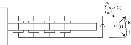
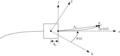
The spacecraft configuration model is shown in Figure 1. It is composed of a rigid hub with two symmetric flexible panels. The hub houses the reaction wheel which is used as a maneuvering actuator that tends to rotate the spacecraft due to total angular momentum conservation. The spacecraft hub can also be rotated using on-off thrusters installed symmetrically on the surface of the hub to generate a torque used for the rotational maneuver of the spacecraft. Each panel contains 2nt piezoelectric patches bonded symmetrically on both sides of the panel and having geometric details as shown in Figures 2 and 3. For the purpose of vibrational energy dissipation, the piezoelectric patches are connected to a resistive-inductive shunt circuit as shown in Figure 4.
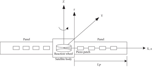
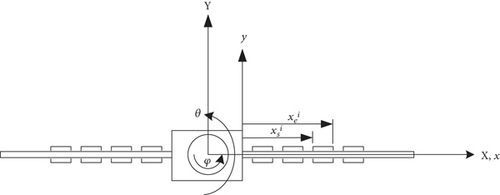
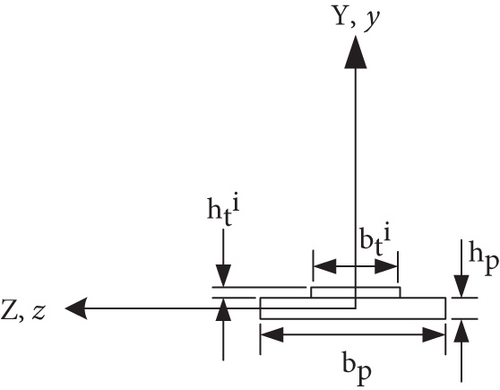
Two coordinate systems are used in this study and are shown in Figures 1, 2, and 3. The first one is the XYZ coordinate system which is a fixed reference frame in space whose origin coincides with the center of gravity of the spacecraft. The second coordinate system is the xyz coordinate system that is fixed to the spacecraft and its origin is located at the center of the left edge of the right panel.
For system modeling, the dynamics of the panels are assumed to behave as Euler-Bernoulli beams where the axial deformations and cross-section rotations are neglected. In addition, the motion considered is a pure rotation of the spacecraft about the Z axis.
2.2. Derivation of the Equations of Motion
The mathematical model is developed that describes the rotational maneuver of the spacecraft hub as well as the transverse displacements of the spacecraft panels along with the shunt circuit. First, the equations of motion in the form of nonlinear partial differential equations are derived using Hamilton’s principle. Then, these equations are transformed into a set of nonlinear ordinary differential equations using the assumed mode method along with Lagrange’s equations.
The first term, in Eq. (17), represents the voltage generated by each piezoelectric patch due to the curvature of the deformed panel, whereas the second term represents the voltage produced by the charge buildup due to the inherent capacitance of the piezoelectric material. V(t) represents the shunt voltage and is defined in Eq. (18).
| i | αiLp |
|---|---|
| 1 | 3.92660261 |
| 2 | 7.06858275 |
| 3 | 10.21017612 |
| 4 | 13.35176878 |
| 5 | 16.49336143 |
| ≥6 | (i + 0.25)π |
3. Modelling in State Space
4. Shunt Circuit Tuning
In this study, several piezoelectric patches are connected in parallel to a single shunt circuit, as shown in Figure 4. Two types of circuits are considered, resistive-inductive circuit (R-L) and resistive circuit (R). The optimal values of inductance (Lopt) and resistance (Ropt) for both circuits that result in the maximum energy dissipation, thereby, achieving maximum vibration suppression is calculated next.
It is assumed that all the piezoelectric patches have the same dimensions and material properties. The optimal tuning values for R and L are calculated using the tuning procedures proposed by Hagood and von Flotow [21].
4.1. Resonant Circuit Tuning
4.2. Resistive Circuit Tuning
5. Time-Optimal Control Design
5.1. Open-Loop Control Design
In this section, we would like to design the torque inputs, τθ and τφ, assuming to have a bang-bang form (on-off) with the objective of performing a quick, rest-to-rest, rotational maneuver with a predefined desired angle. The control design is based on the rigid body mode of the spacecraft alone so that the minimum time is achieved for the maneuver. Consequently, the maneuver will experience excessive vibrations due to neglecting the flexible modes in the control design. The induced vibrations are suppressed by dissipating the vibrational energy using the tuned shunt circuits discussed earlier.
The time-optimal control design is based on the linear model formed by neglecting the nonlinear terms in Eqs. (27)–(30) and by setting the inputs, f(x, t) and V(t), to zeros. Furthermore, Eq. (30) can be used to eliminate q(t) from Eq. (27).
5.1.1. Control Input τθ(τφ = 0)
5.1.2. Control Input τφ(τθ = 0)
From optimal control theory, it is known that the control input structure is of the bang-bang type, which can be characterized by its switching times. Many researchers (see, e.g., reference [16]) have utilized this characteristic to develop numerical techniques that can transfer the time-optimal control problem into parameter optimization problem in terms of the control switching times. They have also noted that as the number of flexible modes in the model increases, the number of control switching times also increases, thereby, making the optimal control problem more difficult, or even impossible, to solve, especially, when the number of modes becomes quite large. On the contrary, the problem becomes very simple when only the rigid-body mode is considered for the control design. In this case, the control input structure is a bang-bang control input that can be characterized by only one switching time (ts) and a final time (tf) as shown in Figure 6.
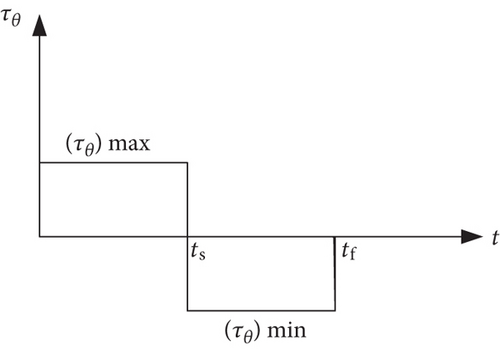
It is assumed that the thrusters can supply a torque input with maximum and minimum magnitudes equal to and , respectively. Similarly, the electric motor for the reaction wheel can provide a torque input with maximum and minimum values equal to and , respectively.
5.2. Necessary and Sufficient Conditions for Optimality
In this section, the necessary and sufficient conditions [22] for the time-optimal control design in the previous sections are laid out.
Where the 2 × 1 vector λ is the costate vector.
Since the system, in Eq. (56), is undamped having one degree of freedom, the time-optimal control solution for a rest-to-rest maneuver has, in most cases, only one switch (ts), and the solution is symmetric about that switch [22].
5.3. Closed-Loop Control Design
In the previous section, the designed time-optimal control torque is calculated based on the switching times and, therefore, it is an open-loop type of control. In this section, a feedback time-optimal control input (τθ) is designed. The control input torque, in this case, is a function of the system states, thereby, requiring sensors to be added to the satellite system. The added cost is for the benefit of added control accuracy and improved control system performance against disturbances and parameter variations. It is assumed that all the states required for feedback are available to the control system.
And y1 and y2 are the last elements of the (n + 1) × 1 vectors ϱ and , respectively.
In the numerical simulation, the switching function and the control torque τθ is calculated by integrating the state equations, Eq. (44) and then calculating the states y1 and y2 to construct the switching function, Eq. (67), in order to compute the control torque τθ. Finally, the computed input torque τθ is applied to the nonlinear equations of motion, Eqs. (27)–(30).
It is noted that the previous feedback time-optimal control design which is based on the rigid-body mode in the modal coordinates requires all the states of the system to be available. In practice, this is achieved using either sensors or by estimating the states using state observer. To overcome this obstacle, we will attempt to use the rigid-body mode, in the physical coordinates, in the feedback time-optimal control design. This is due to the fact it is much easier to measure the angular velocity and angular displacement of a spacecraft rather than the whole states of the system.
6. Numerical Simulations
The objective of this section is to perform numerical simulations for the spacecraft maneuver using the procedures outlined in the previous sections. The parameter values for the components of the spacecraft are given in Table 2.
| Spacecraft body | Panel (aluminum) | Transducers (PZT-4) | |||
|---|---|---|---|---|---|
| Parameter | Value | Parameter | Value | Parameter | Value |
| Rs | 0.3 m | Lp | 3 m |
|
m |
| Js | 720 kg·m2 | bp | 0.2 m |
|
m |
| Jr | 1 kg·m2 | hp | 0.003 m | bt | 0.2 m |
| ns | 2 | Ep | 73.1 GPa | ht | 0.001 m |
|
|
100 N·m | ρp | 4.275 kg/m | ρt | 2.25 kg/m |
|
|
−100 N·m | np | 2 |
|
134.9 GPa |
|
|
100 N·m |
|
132 GPa | ||
|
|
−100 N·m | h31 | −702.2 × 10⁶ N/C | ||
| d31 | −0.118 × 10⁻⁹ C/N | ||||
|
|
171.3 × 10⁶ m/F | ||||
|
|
5.84 × 10⁻⁹ F/m | ||||
|
|
10.66 × 10⁻⁹ F/m | ||||
In the simulation, two panels are assumed to be connected to the spacecraft body, and a grid of identical piezoelectric transducers is attached to each panel. It constitutes of four patches along the panel width (z-direction) and twenty-three patches along its length (x-direction). The dimensions of each piezoelectric patch is assumed to be 0.05 m × 0.05 m × 0.001 m. Therefore, there is no gap between adjacent patches along the panel width and 0.01 m gap between adjacent patches along the panel length.
The designed time-optimal control input is intended to perform a rest-to-rest maneuver and rotate the spacecraft from an arbitrary initial angular position (θ(0) = 0°) to a desired final position (θ(tf) = 30°) using either the spacecraft body torque, τθ, or the reaction wheel torque, τφ, with minimum time.
The MATLAB® function ode23t is used to numerically integrate the nonlinear equations of motion, Eq. (34), using trapezoidal rule. In this function, the absolute and relative tolerances are set to 10−6. The number of admissible functions that are used in the simulations is equal to ten.
Calculations of the optimal values of the shunt circuit elements, Ropt and Lopt, require the estimate of the open- and short-circuit natural frequencies of the system. This can be done by solving the eigenvalue problem associated with the linearized model of the spacecraft system. The linear model can be obtained by neglecting the nonlinear terms in Eqs. (27)–(30). The short-circuit natural frequencies can be calculated from the eigenvalue problem associated with the linear model by setting all the inputs, including the voltage (V(t)), to zero, whereas the open-circuit natural frequencies are calculated using the same eigenvalue problem as that for the short-circuit in addition to setting the charge vector (q(t)) to zero.
The calculated lowest ten open- and short-circuit natural frequencies, excluding the zero frequency for the rigid- body mode, are shown in Table 3.
| Mode number | Open circuit (rad/s) | Short circuit (rad/s) |
|---|---|---|
| 1 | 2.5809 | 2.5654 |
| 2 | 9.4118 | 9.3751 |
| 3 | 26.5285 | 26.4436 |
| 4 | 51.7010 | 51.4763 |
| 5 | 83.5376 | 83.2849 |
| 6 | 130.2304 | 129.7114 |
| 7 | 174.9599 | 174.2704 |
| 8 | 238.3717 | 237.7104 |
| 9 | 335.6923 | 333.4387 |
| 10 | 448.1666 | 444.7829 |
The optimal values of the resistance (Ropt) and the inductance (Lopt) for both the resonant as well as the resistive shunt circuits are calculated using Eqs. (35), (36), and (43) with their calculated values shown in Table 4. Furthermore, these circuits are tuned to target the first vibrational mode because it is assumed to contribute the most in the system response.
| Resonant | Resistive | |
|---|---|---|
| (rad/s) | 2.5809 | |
| (rad/s) | 2.5654 | |
| δopt | 1.00605 | — |
| ropt | 0.153926 | — |
| K | 0.110163 | — |
| (F) | 3.370095 × 10⁻⁷ | |
| Ropt (Ω) | 1.112737 × 10⁴ | 6.576392 × 10⁴ |
| Lopt (H) | 2.784116 × 10⁴ | — |
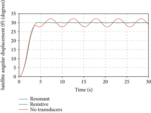
To demonstrate the effect of the tuned shunt circuits on the spacecraft response, numerical simulations for three cases: resonant shunt circuit, resistive shunt circuit, and no transducers are shown. The desired maneuver is a rest-to-rest rotational maneuver of 30° assuming a maximum available torque of 100 N·m from either the spacecraft thruster or the reaction wheel motor. The resulting time-optimal control switching and final times for the thruster torque (τθ) are calculated using Eqs. (54) and (55) to give 2.0897 sec and 4.1795 sec, respectively. Therefore, the total maneuver time is 4.1795 sec, which is the least maneuver time possible corresponding to the specified spacecraft parameters and the maximum torque available. If the reaction wheel motor torque (τφ) is used instead of the thruster torque (τθ), then the same maneuver can be achieved with the same switching and final times by only reversing the torque direction (i.e., applying negative torque from times 0 to ts and positive torque from times ts to tf).
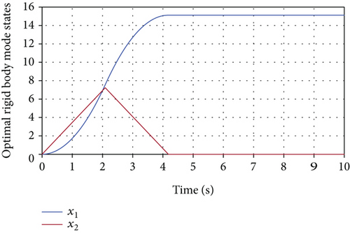
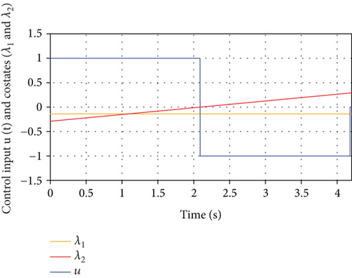
The necessary and sufficient conditions of optimality, outlined in Section 5.2, are utilized to verify the optimality of the resulting control input for the rigid-body mode. Using the system parameters in Table 2 along with the value of the target maneuver, one can easily calculate the values of ϕ = 0.0346266 and in Eqs. (57) and (58). Equations (56), (57), (58), and (64) can be used to solve for the time-optimal control input, states, and costates. The resulting time-optimal states for the rigid body mode are shown in Figure 7, whereas the time-optimal control input, normalized by umax, and the costate variables are shown in Figure 8. As seen in Figure 8, the switching function, represented by the costate (λ2(t)) vanishes only at the control input switching time (ts = 2.08972 sec) which proves that the control input and costates satisfy all the necessary and sufficient conditions of optimality, Eq. (64), and are, therefore, optimal. The next step is to apply the time-optimal control torque for the rigid-body mode to whole spacecraft represented by Eq. (34).
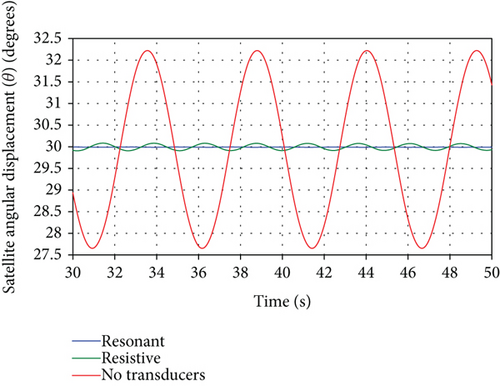
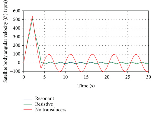
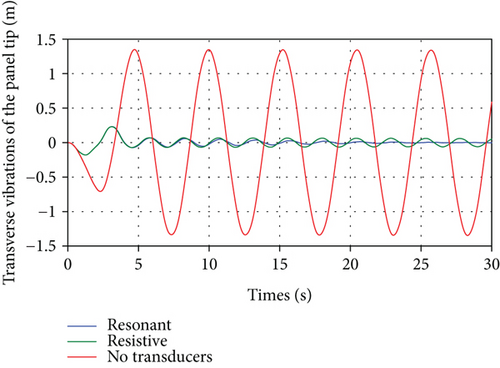
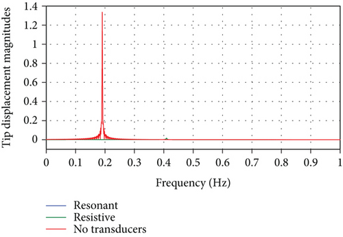
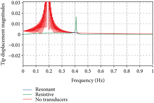
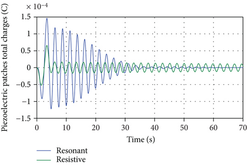
The resulting spacecraft orientation angle time histories, θ(t), for the aforementioned three cases are shown in Figure 9. It can be noted that the influence of the panel vibrations on the spacecraft attitude leading to sustained oscillations can be eliminated completely by using the resonant shunt circuit and partially by using the resistive shunt circuit. The degree of effectiveness of both shunt circuits can be seen by the zoomed portion of the attitude response shown in Figure 10 showing superior vibration suppression by the resonant shunt compared to resistive shunt. Similarly, Figure 11 depicts the time histories for the spacecraft angular velocity, in rpm, for the three cases. The effectiveness of the passive piezoelectric shunts can also be seen in the simulation of the transient as well as the steady-state responses of the panel tip transverse vibrations, shown in Figure 12. Both shunt circuits are able to dissipate the vibrational energy significantly by adding damping to the system compared with the case when no transducers are used. Moreover, the resonant (R-L) circuit provides more effective vibration control than its resistive (R) circuit counterpart as indicated by the faster vibrational amplitude decay. Similar conclusions can be drawn by observing the frequency response of the panel tip vibrations, calculated by performing DFT transform of the time response, shown in Figure 13 and with its zoomed portion in Figure 14, demonstrating the effectiveness of the shunt circuits on the system dynamic response. As to the electric behavior of the electromechanical system, the total electric charges, generated by the piezoelectric patches, during the spacecraft maneuver is shown in Figure 15. It can be seen that the total charges generated by the resonant shunt circuit is more than that generated by the resistive counterpart indicating more vibrational energy dissipation and, thereby, achieving more accurate spacecraft maneuver.
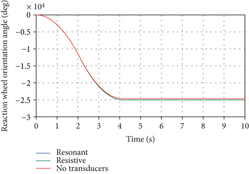
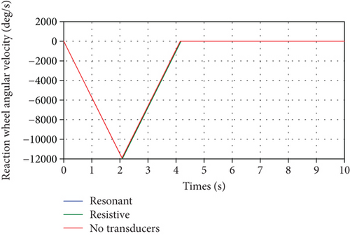
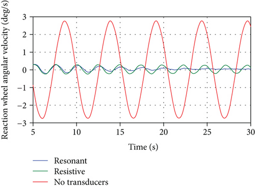
As mentioned earlier, the spacecraft maneuver can also be performed by applying torque (τφ) to the reaction wheel through its motor. This torque has the same form as the spacecraft body torque (τθ) but with control values having opposite sign. The resulting spacecraft orientation angle, θ(t), is exactly the same as that shown in Figure 9. Moreover, the reaction wheel angular displacement relative to the spacecraft body, φ(t), and its time rate are shown in Figures 16 and 17, respectively. Finally, Figure 18 displays the zoomed part of Figure 17 to show the effectiveness of both shunt circuits on the reaction wheel angular velocity.
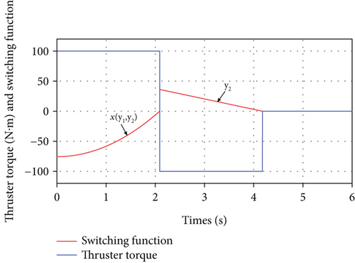
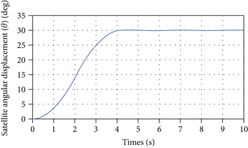
In the feedback time-optimal control torque design simulation based on the rigid-body mode in the modal coordinate, discussed in Section 5.3, only the resonant case is shown. The switching function, Eq. (67), and the resulting control torque, τθ, Eq. (66), are shown in Figure 19, whereas the spacecraft orientation angle, θ(t), is shown in Figure 20. It can be seen that the feedback time-optimal thruster control design using resonant shunt circuit is able to dissipate the vibrational energy resulting from neglecting the flexible modes to achieve accurate rotational maneuver. Furthermore, the thruster switching and final times are 2.0897 sec and 4.1795 sec, respectively, which are the same as the ones calculated in the open-loop case.
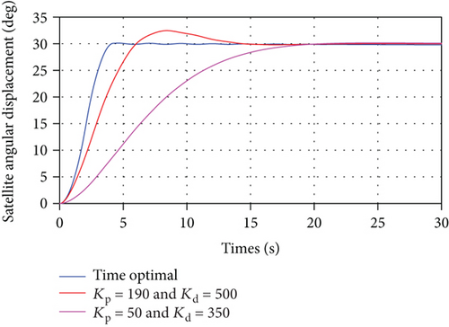
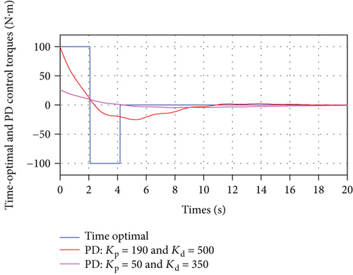
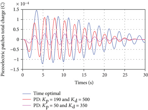
In the feedback time-optimal control torque design based on the rigid-body mode in the physical coordinates, Eq. (69), the coefficient multiplying the control torque, τθ, is equal to 0.0012. The switching and final times for a 30o maneuver calculated using Eqs. (54) and (55) are 2.0897 sec and 4.1795 sec, respectively, which are exactly the same values obtained using the rigid-body mode in the modal coordinates. Furthermore, the resulting rigid-body mode solution satisfies all the necessary and sufficient conditions of optimality. Therefore, the rigid-body model in Eq. (69) can be used in both the open-loop and the closed-loop time-optimal control design. To show the effectiveness of the proposed time-optimal closed-loop control design method, it is compared with PD controller, with a control law given in Eq. (70). The challenge in this comparison is that the PD control design depends on the selection of the values of the proportional and derivative gains, Kp and Kd, respectively. Based on some trial and error procedure, two cases of PD control design are compared with the proposed closed-loop time-optimal control design method. The values of Kp and Kd for the first case are 190 and 500, respectively, whereas they are 50 and 350, respectively, for the second case. The value of Kp in the first case results in an initial control torque equals to that for the time-optimal control torque (i.e., 100 N·m) so that a fair comparison is made with regard to the final maneuver time. The values of the second PD controller case results in a low level of vibrations in the transient response. Using the spacecraft parameter values shown in Table 2 and the tuned parameters for the resonant and resistive shunt circuits shown in Table 4, the response of the nonlinear system in Eq. (34) is calculated and displayed in Figures 21, 22, and 23. The spacecraft angular displacement resulting from the application of the time-optimal control torque as well as the two PD control torques are shown in Figure 21. It is seen that the final steady state is reached by the time-optimal control response faster by 245% and 375% compared with that for the first case and second case PD responses, respectively. The time-optimal and PD control torques are shown in Figure 22. It can be noticed that the two PD control torques are applied for a longer time than that for the time-optimal control torque. The total generated piezoelectric charge resulting from the application of the time-optimal control and the two PD controls are shown in Figure 23. The time-optimal control response experiences more generated charge and, thereby, more vibration suppression compared with that for the two PD control responses.
7. Conclusion
The mathematical modeling, in the form of nonlinear partial differential equations, for a spacecraft consisting of a rigid body connected with flexible panels with bonded piezoelectric transducer patches is developed. The transducers are connected to either resonant or resistive shunt circuits to add damping to the system to suppress the flexible panel vibrations during and after a maneuver. The model is then transformed to nonlinear ordinary differential equations using the assumed mode method. This model is then used to design a time-optimal control torque to perform a fast, rest-to-rest, rotational maneuver using either the rigid body thrusters or the reaction wheel motor. The control design is based on only the rigid body mode to achieve the fastest maneuver possible. In addition, the resulting control structure is bang-bang with only one switching time. The induced vibrations resulting from neglecting the flexible modes of the panels are suppressed using piezoelectric transducers along with the shunt circuit. Two types of shunt circuits, namely, the resonant (R-L in series) and the resistive (R) circuits, are used in this study. The values of the parameters used in the shunt circuits, namely, resistance (R) and inductance (L), are tuned so that maximum vibration suppression is achieved. Numerical simulations show the ability of the resonant circuit to eliminate the system vibrations completely while the resistive counterpart reduces the vibrational amplitudes significantly when compared with the case when no transducers are used. Furthermore, the passive shunt circuits do not require energy for its operation and, therefore, has the advantage over any active vibration control method. However, the resonant shunt circuit may require large values for the inductance, especially when targeting low-frequency modes. Many researchers have proposed solutions to circumvent this problem such as by using synthetic inductors [24]. Finally, a feedback time-optimal thruster torque is synthesized using the rigid body mode in both modal and physical coordinates. This form of control input provides better accuracy as well as system performance over its open-loop counterpart. The resulting switching times, control torque, and satellite orientation angle are very similar to their open-loop counterpart. The numerical simulations show the effectiveness of the time-optimal feedback control design compared with that resulting from the proportional and derivative feedback control design.
Conflicts of Interest
The author declares that there is no conflict of interest regarding the publication of this paper.
Acknowledgments
The author would like to acknowledge the support provided by the Deanship of Scientific Research at King Saud University through the Research Center at the College of Engineering.


