Dynamics Analysis of Deployable Structures considering a Two-Dimensional Coupled Thermo-Structural Effect
Abstract
The deployment accuracy of deployable structures is affected by temperature and flexibility. To obtain the higher accuracy, various measures such as the optimization design and the control process are employed, and they are all based on deployment dynamics characteristics of deployable structures. So a precise coupled thermo-structural deployment dynamics analysis is important and necessary. However, until now, only a one-dimensional thermal effect is considered in the literatures because of simplicity, which reduces the accuracy of the model. Therefore, in this paper, a new model coupling mechanical field with a temperature field is presented to analyze the deployment dynamics of a deployable structure with scissor-like elements (SLEs). The model is based on the absolute nodal coordinate formulation (ANCF) and is established via a new locking-free beam element whose formulation is extended to account for the two-dimensional thermally induced stresses due to the heat expansion for the first time. Namely, in the formulation, the thermal influences are along two-dimensional directions, the axial direction and the transverse direction, rather than along a one-dimensional direction. The validity and precision of the proposed model are verified using a flexible pendulum example. Finally, the dynamics of a linear deployable structure with three SLEs modeled by the element is simulated under a temperature effect.
1. Introduction
Over the past three decades, deployable structures have been extensively used in space missions because they own the properties of high stiffness, low mass, and small folding volume [1–4]. And with the rapid development of aerospace industry, higher demands for these structures have been proposed. One of the most important is higher deployment accuracy, which is affected by thermal and flexible effects [5].
In order to achieve higher accuracy, the precise deployment dynamics characteristic of deployable structures is essential because it is fundamental to the optimization design [6] and the control process [7]. However, due to the high cost of the imitated space environment on the ground, it is difficult to predict the dynamic capability of these structures by experiment. So some practical methods are developed for dynamic analysis of these flexible structures. The most classical approach is the floating frame of reference formulation [8], but it is deficient in dynamic stiffening and will lead to an imprecise simulation result. To overcome this drawback, Shabana presented a new approach called the absolute nodal coordinate formulation (ANCF) [9], which can satisfy the dynamic stiffening automatically [10, 11] and leads to a constant mass matrix and zero centrifugal and Coriolis forces [12]. Because of these advantages, several beam elements [11, 13–16], plate elements [17], and brick elements [18] applied to analyze various objects of study have been developed within this formulation. A two-dimensional shear beam element proposed by Omar and Shabana [11] to consider the shear deformation effect is among them. However, in a later research, it was found out that this beam element deriving elastic forces on the basis of the nonlinear elastic theory suffers from volumetric Poisson’s locking, thickness locking, and shear locking, which influence the accuracy and computational efficiency of ANCF greatly [19, 20]. In order to avoid the Poisson’s locking, an exact description of elastic forces is presented by Sopanen and Mikkola [21], but the simplest way is setting the Poisson ratio to zero directly. Possible alternatives to solve other locking problems are selective reduced integration [22–24] and the redefinition of elastic forces based on the Hellinger-Reissner principle [20, 25].
As the absolute nodal coordinate formulation grows and is verified in many fields [26, 27], some researchers start to apply it in space deployable structures. Li et al. [28] use ANCF to simulate the deployment dynamics of the deployable antenna reflector. Tian et al. [29] simulate the deployment dynamics of two types of deployable structures based on ANCF and find a good agreement between simulations and experiments. In these simulations, all of researchers do not take into account the temperature effect and only investigate the deployable systems under the normal temperature. Li and Wang [30] fill the gap by discussing the deployable driving torque at the lowest and highest temperature within ANCF, but their model is based on a simple Euler–Bernoulli beam element and only the axial thermal effect is pondered. As mentioned above, however, a precise dynamics analysis is important and necessary for deployable structures. Besides, several high-profile examples have verified that the temperature effect has a great influence on deployable structures [31, 32]. So the multidimensional coupled thermo-structural effect on the deployment process of deployable structures must be considered.
To this end, a new model coupling mechanical field with a temperature field of a deployable structure with scissor-like elements (SLEs) based on ANCF is presented. The model is established by a new planar locking-free shear deformable beam element inspired from the gradient-deficient element which alleviates the thickness locking. In order to simulate the deployment dynamics characteristic accurately, the formulation of the shear deformable beam element is extended to contain the thermal stress due to heat expansions. Note that the temperature field is uniform and the heat expansions are along two-dimensional directions; that is to say, the thermal loads are applied in an axial direction and a transverse direction, which is a great improvement compared with that of Li and Wang [30]. Also, the heat expansion coefficients are equal in two-dimensional directions because of the isotropic material in the model. This formulation is verified by ANSYS with a simple pendulum driven by gravity. In the end, on the basis of the new model, the simulation results of deployment dynamics of the deployable structure considering the coupled thermo-structural effect are calculated out and compared with results of only flexible analysis of the same structure to discuss the temperature effects.
This paper is organized as follows. The coupled thermo-structural formulation of the locking-free shear deformable beam element with two-dimensional thermal loads is discussed in Section 2. In Section 3, the formulation is demonstrated and a model of the deployable structure consisting of SLEs is established with the formulation. Also, the coupled thermo-structural analysis of other deployable structures comprising rods can be created by using this formulation. The simulation results of the deployable structure with SLEs are illustrated in Section 4. Finally, some valuable conclusions are drawn in Section 5.
2. A Locking-Free Shear Deformable Beam Element under the Thermo Effect
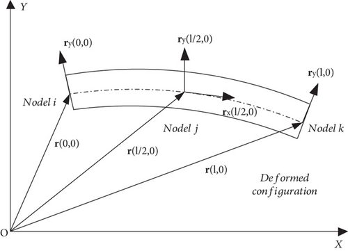
In this paper, using a two-dimensional shear deformable beam element [11] to model the rods is appropriate because motions and forces of the deployable structure with SLEs are in plane and no torsion occurs. However, the beam element suffers from the locking phenomena. So a new locking-free shear deformable beam element is presented in Figure 1. In the improved beam kinematics, an additional slope vector rx is added in the middle of the gradient-deficient element [19].
3. Validation
A simple example that a rectangular pendulum moves from the horizontal rest position under the effect of gravity (g = 9.8 m/s2), as shown in Figure 2, is examined to validate the proposed model with a two-dimensional thermal load based on ANCF. And the thermal load is applied by changing the temperature from 0°C to 200°C suddenly. And other simulation parameters such as the material property and geometry size of the pendulum are given in Table 1.

| Characteristic parameters | Values |
|---|---|
| Length L (m) | 1 |
| Cross-sectional area A (m2) | 0.02 × 0.02 |
| Material density ρ (kg/m3) | 7750 |
| Elasticity modulus E (N/m3) | 2 × 10⁸ |
| Poisson’s ratio ν | 0 |
| Thermal expansion coefficient αT (K−1) | 2.85 × 10⁻⁵ |
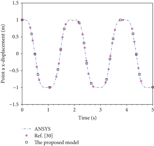
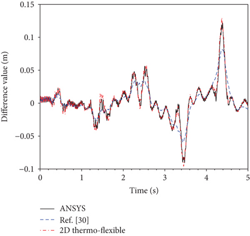
Figure 3 shows the curves of displacement of point a which are evaluated by ANSYS, the 1D thermo-structural model [30], and the proposed model, respectively. The two models are in good agreement with ANSYS within a large overall motion. It demonstrates that the proposed beam element is free of locking phenomena. Further, in order to observe the difference among three results clearly, a margin calculation is carried out. The difference between ANSYS and the flexible model, the difference between the 1D thermo-structural model and the flexible model, and the difference between the proposed model and the flexible model are compared in Figure 4. Here, the flexible model implies no temperature effect. It is clear from the difference value present in Figure 4 that the proposed model is in good agreement with ANSYS, whereas the 1D thermo-structural model has a huge gap with ANSYS. So the proposed model has higher precision. Therefore, the development of the new two-dimensional thermo-structural model is significant.
4. Numerical Results
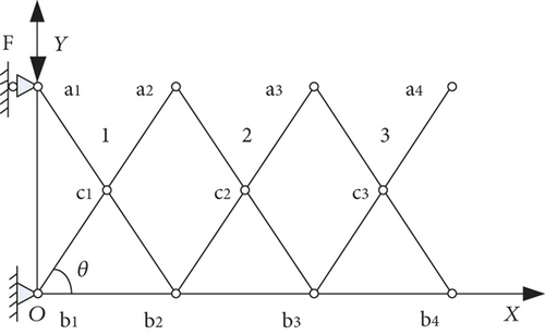
In this section, a deployable structure with three scissor-like elements considering the coupled thermo-structural effect is discussed. As shown in Figure 5, a scissor-like element is assembled by two rods which can be treated as beams with a pin, and the three scissor-like elements are connected to a deployable system with pins. A driving force equal to 50 N is applied at point a1. The material property and geometry size of the structure are given in Table 2. And the motion simulation is carried out within the time interval t ∈ [0, 3]s, where the system is uniformly revelational to the temperature profile presented in Figure 6 with a maximum temperature of 150°C and a minimum temperature of −150°C [30]. In order to demonstrate the temperature influence on the dynamics of the mechanism, the simulation results are compared with the same system only considering the flexible effect.
| Characteristic parameters | Values |
|---|---|
| Length L (m) | 2 |
| Cross-sectional area A (m2) | 0.02 × 0.02 |
| Material density ρ (kg/m3) | 2750 |
| Elasticity modulus E (N/m2) | 7 × 10¹⁰ |
| Poisson’s ratio ν | 0 |
| Thermal expansion coefficient αT (K−1) | 2.3 × 10⁻⁵ |
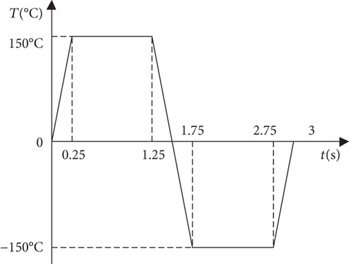
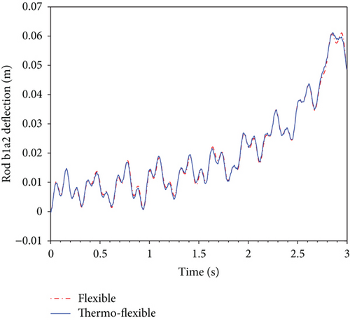
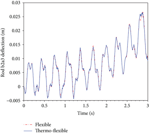
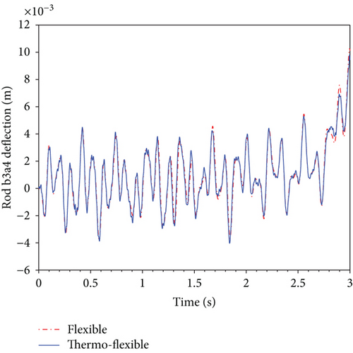
Figure 7 shows the deflection curves of rod b1a2, rod b2a3, and rod b3a4 in the changing temperature field as shown in Figure 6 and in the constant temperature field. Referring to Figure 7, it can be seen that the time-dependent temperature leads to many small vibrations which can be observed 2.7 s after clearly when the two curves differ greatly at the moment. These small vibrations which will influence the deployment accuracy greatly arise because thermally induced transverse strain results in varying moment of inertia related to the cross-sectional area besides the change of the length of rods resulting from thermally induced axial stress. Another notable point from the pictures is that the temperature influence on the deflection of the rods seems to weaken in this time period of 2 s to 2.5 s. A probable reason is that the lowest temperature effect on the deployable structure partly offsets the highest temperature effect in the earlier period.
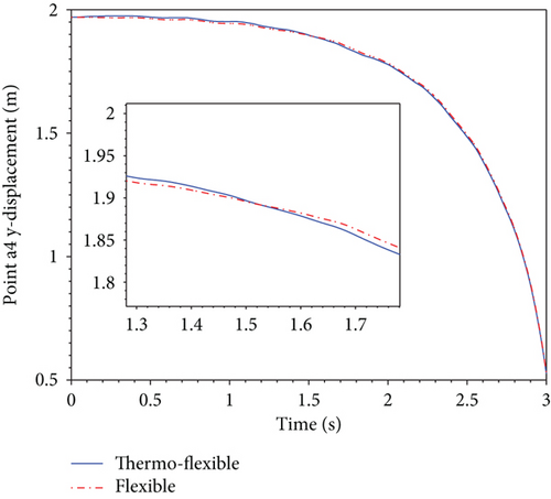
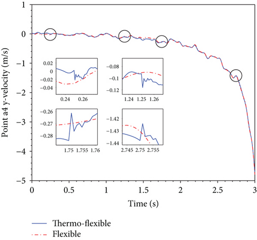
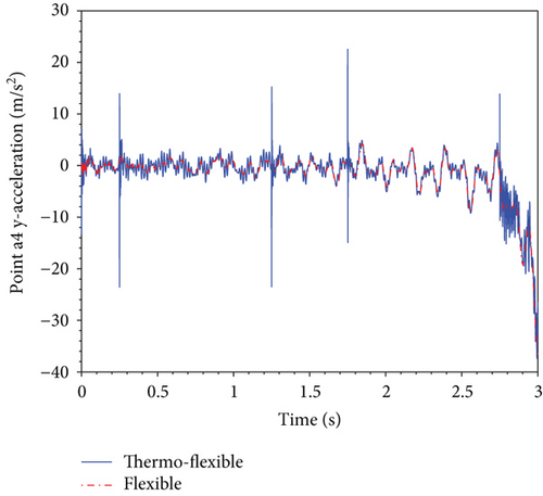
The motion diagrams of a representative point a4 selected to stand for the dynamics characteristics of the deployable structure are shown in Figure 8. Referring to Figure 8, the temperature impacting on deployment displacement and velocity is not obvious, but there is a huge influence on deployment acceleration of point a4. The thermal effect results in additional vibrations emerging in acceleration, which can be observed by comparing the thermo-flexible curve with the flexible curve. Besides, referring to Figures 6 and 8(c), it is found that acceleration vibrations become larger perspicuously at inflection points of the temperature profile such as 0.25 s, 1.25 s, 1.75 s, and 2.75 s. These vibrations may lead to unexpected collision and impact which might result in the invalidation of the deployable structure or even mission failure.
5. Conclusions
- (1)
In order to establish the precise model coupling of the mechanical field with the temperature field of the mechanism, the formulation of a new locking-free beam element with the additional slope vector is extended to account for the thermally induced stresses in two-dimensional directions, that is, the axial direction and transverse direction
- (2)
It shows that the new beam element is free of locking phenomena as a result of a good agreement between the calculating results of the simple pendulum and the simulation results of the ANSYS within a large overall motion. Then, the validity and the precision of the proposed thermo-structural model are demonstrated through the further margin calculation: the difference of the proposed model is approximately identical to the difference of ANSYS, whereas the difference of the 1D thermo-structural model has a relatively large gap with the difference of ANSYS. Therefore, the proposed model is more precise than the 1D thermal-structural model. On the other hand, it also demonstrates that the development of the new two-dimensional thermo-structural model is significant
- (3)
In the final simulations of the deployable structure, by contrasting the thermo-flexible deflection with the flexible deflection, it is found that the main influence of temperature is that the change of temperature leads to many vibrations: for the deflection of rods, many small vibrations arise because thermally induced transverse strain results in varying moment of inertia related to the cross-sectional area besides the change of the length of rods resulting from thermally induced axial stress. On the other hand, for the deployment dynamics characteristics, temperature has a huge impact on deployment acceleration. The thermal effect will result in additional vibrations emerging in acceleration of an arbitrary point on the deployable structure, and these vibrations will become larger perspicuously at inflection points of temperature change
Conflicts of Interest
The authors declared no potential conflicts of interest with respect to the research, authorship, and/or publication of this article.
Acknowledgments
This work was supported by the National Natural Science Foundation of China (grant number 51175422).
Appendix
Open Research
Data Availability
The data that support the findings of this study are available from the corresponding author upon reasonable request.


