Aerothermodynamic Effects and Modeling of the Tangential Curvature of Guide Vanes in an Axial Turbine Stage
Abstract
By tangential curvature of the stacking line of the profiles guide vanes can be designed, which have on both ends an obtuse angle between suction side and sidewall. This configuration, according to literature, is capable of reducing secondary loss. This type of vanes develops considerable radial components of the blade force and effects a displacement of the meridional flow towards both sidewalls. In this paper we work with a finite-volume-code for computations of the three-dimensional Reynolds averaged Navier-Stokes equations for an axial turbine stage with radial and two types of tangentially curved guide vanes. With computational results, mathematical formulations are developed for a new flow model of deflection of such blades that are formally compatible with the assumption of a rotation-symmetrical flow and with the existing throughflow codes, in order to predict the deflection angle over the blade height for the tangential leaned and curved blades.
1. Introduction
The classic design method for the blading of axial turbines, applied for many decades, stipulates that the profiles constituting the blade body are stacked in radial direction. Such stacked profiles can be different forms in the case of twisted blades. When such blading profiles are arranged with the profile centers of inertia on a radial line, the stacking line, bending stress by centrifugal force is avoided in rotor blades. The normal of the surface elements of blades designed accordingly is directed essentially to be tangential-axial, so that the pressure forces of the blades have no or quite small radial components; these are usually neglected in the aerodynamic calculation. Consequently only the radial pressure gradient and the centrifugal force resulting from the circumferential component of the flow velocity are acting in radial direction on the fluid particles passing through the turbine stage. Minor additional radial forces may result from streamline curvature and inclination. They enter as important parts into the equation of radial equilibrium, which is one of the basic equations for the fluid-dynamic design of axial turbomachines.
The classic blade design results in difficulties, particularly in the case of long blades as in the LP-part of condensing steam-turbines (e.g., [1]), because the large radial pressure gradient in the gap between stator and rotor causes a considerable variation of the degree of reaction over the blade length (e.g., 0% at the hub and 80% at the tip), which complicates blade design and reduces efficiency.
Consequently the idea was born by Deich et al. [2], to produce additional blade forces in radial inward direction by circumferential inclination of the stator blades in order to counteract the centrifugal forces and so to reduce the radial pressure gradient. The idea proved successful and caused extensive research on different blade forms with nonradial surface elements (e.g., [3–6]).
It was found in addition that a blade inclination in the sidewall area, which produces an obtuse angle between blade suction side and sidewall, can reduce secondary loss, while an acute angle will increase it. A pure inclination of the stacking line in circumferential direction (lean) will therefore create a positive effect on secondary loss at one end of the blade and a negative effect at the other end. Such inclined blade has been discussed by several authors; see, for example, Deich et al. [2, 7–9]; Han et al. [10, 11]; Harrison [12]; Hourmouziadis and Hübner [13]; Suslov and Filippov [14]; Wang et al. [15], an experiment research, and Deich et al. [2, 7–9]; Hourmouziadis and Hübner [13]; Pioske and Gallus [16]; Smith Jr. and Yeh [5]; Suslov and Filippov [14], a numerical research, as well as the references therein.
In order to realize the loss reducing obtuse angle between suction side and sidewall on both ends of the blade a curvature (bow) of the stacking line of the profiles is necessary. For stator blades this can be realized without mechanical trouble. This design appears favourable especially for short blades, as in height pressure (HP) and middle pressure (MP), part of steam-turbines, since there secondary loss together with clearance loss amounts to 20–40% of the total aerodynamic loss, while a reduction of the radial pressure gradient, not realizable with this type of blade, is not important. The research work of the flow in axial turbine stages with curved stator blades is therefore an important research topic for actual turbomachinery and aeroengines. And some results of the curvature blades can be found in Deich et al. [7–9]; Filippov and Wang [17, 18]; Wanjin et al. [11]; Harrison [12]; Hourmouziadis and Hübner [13]; Jiang et al. [19]; Vogt and Zippel [20]; Wang and Zheng [21]; Wolf and Romanov [22], an experiment research, and Filippov et al. [18, 23]; Hourmouziadis and Hübner [13]; Jiang et al. [19]; Pioske and Gallus [16]; Suslov and Filippov [14]; Wang and Zheng [21], a numerical research, where the curvature form of such researches is however mostly a simple curvature (circle) form.
Experimental researches and numerical computations are available as tools to obtain a detailed knowledge of the 3D-flow field and to understand the effect of geometric modifications. Simulation offers the opportunity of a very detailed insight in the complete flow field which is hardly accessible by experimental means. In addition it is ideally suitable for systematic research of geometry variations, as necessary in the present case. However, the quality of simulation results will be influenced by numerical iteration procedure, turbulence model, mesh-structure, wall-flow model, and so forth in a way that is difficult to control. It is therefore highly recommendable to validate the results of simulation with the aid of experimental data, as has been possible in the present case.
- (i)
effects of blade curvature on the flow in the stator,
- (ii)
effects of the stator blade curvature on the flow in the rotor (which remained unchanged in geometry),
- (iii)
effects of the blade curvature on stage characteristic,
- (iv)
new modeling of the radial blade force and the deflection angle over the blade height for the tangential leaned and curved blades that are formally compatible with the assumption of a rotation-symmetrical flow and with the existing throughflow codes.
Definition of Curved Blade. The research is restricted to stator blades curved of both ends as follows. The stacking line of the profiles is curved in circumferential direction as, for example, in Figure 1.
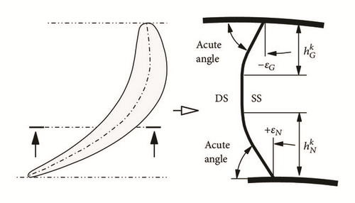
The curvature is defined by the angle ε between the stacking line and the sidewall at the blade end and by the extension hk of the nonradial part of the stacking line. These values can be different at both ends of the blade.
(i) Positive Tangential Blade Curvature. If an acute angle between the pressure side DS and the sidewall is realized, the curvature is defined as positive.
(ii) Negative Tangential Blade Curvature. A blade with negative curvature shows acute angles between suction side SS and sidewall.
2. Computational Methods
The applied numerical procedure solves the 3D-time-dependent Reynolds averaged Navier-Stokes equations with the finite volume method and comprises different turbulence models. Some validations showed a very good quality of the results. For turbomachinery as well as aeroengine applications the program contains a procedure for circumferential averaging of flow parameters in planes between blade rows, for example, between stators and rotor, in order to make a steady-state calculation feasible in both blade rows. A suitable averaging plane was provided in the grid design. The calculation used the Baldwin-Lomax turbulence model [24] and a three-level full multigrid method for convergence acceleration. Our simulation results showed a difference of mass flow in the inlet and outlet plane of less than about 0.02%. Details on the computational methods of this code are available in some literatures, for example, [25–30].
2.1. Governing Equations
2.2. Method of the Spatial Discretization
The spatial fluxes of the applied basic equations of (1) and (2) are actually discretized using the finite volume scheme. The finite volumes scheme has been usually spread using numeric technology in particular for flow problems, because the integral form of the conservative equations can be interpreted by direct discretization for a volume cell of the grids with the structured as well as unstructured grids very flexibly and easily [25, 27, 29, 30].
2.2.1. Numerical Fluxes
For the Navier-Stokes equation, the friction-affected dissipation is normally not sufficient in the solution and therefore is the above term of the artificial dissipation necessarily by the numeric solution of the Navier-Stokes equation. The unexpected difficulty with this approximation hence comes from the fact that the solution and the convergence can be strongly dependent on the coefficients [25, 27]. This approximation will be used with either explicit or implicitly temporal integration.
2.3. Turbulence Model
Since there is still no universal and general turbulence model, the turbulence model will govern the results simulated [24, 25, 27]. In this study, Baldwin-Lomax turbulence model, which is suitable for the wider class of interference model to achieve enough accurate and reliable results for a turbomachinery, is chosen for the fully turbulence condition. The added blended wall function implemented in the Baldwin-Lomax turbulence model leads to the boundary layer at the solid walls with further refinement by y+ value with y+ ≈ 1.
3. Computational Conditions
As a starting point data from an experimental research of a single stage air turbine with different types of curved guide vanes were made available to us by the department for power, nuclear turbine construction, and aircraft engines of State St. Petersburg Technical University (Russia). They comprised stage characteristics as well as detailed flow measurements with aerodynamic probes. Comparison of these data with the results of numerical simulation of the same geometries, reported in [36], showed good agreement and served as validation of the simulation technique chosen. A number of stator configurations with different types of bow was derived from the geometry of the experimental turbine and investigated numerically.
3.1. Single Stage Experimental Air Turbine
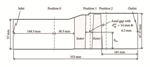
Figure 2 shows the meridional section of the turbine, the test results of which have been used for the validation of the numerical simulation procedure. For the measuring planes positions 0, 1, and 2 data of probe measurements were available. The extension of the meridional section in Figure 2 shows, too, the field of the numerical calculation.
3.2. Geometrical Data of the Researched Blades
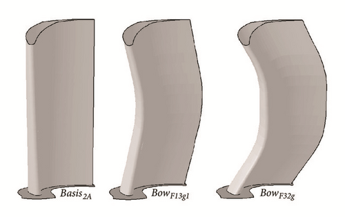
The experimental investigations were made for a radial guide vane Basis2A and a curved guide vane Bow2B, both combined with the same rotor. Characteristic data of the center-line profiles are given in Table 1. For the numerical research 8 different stator blade rows have been calculated with a systematic variation of curvature by tangential displacement of the unchanged profiles of the radial stator Basis2A. Results are given here for the basis blading and the two most characteristic bow stators. Data describing the curvature are shown in Table 2; the parameters describing the curvature are ε and the relative extension according to Figure 1. Figure 3 shows a 3D representation of the three guide vanes.
| Notation | Unit | Basis2A | Bow2B | Rotor |
|---|---|---|---|---|
| Blade height | [mm] | 65.6 | 65.6 | 66.87 |
| Middle diameters | [mm] | 363.98 | 363.98 | 364.24 |
| Blade chord | [mm] | 31.159 | 32.101 | 20.26 |
| Max. camber | [mm] | 7.047 | 5.254 | 6.063 |
| Stagger-angle | [deg.] | 43.00 | 36.00 | 57.20 |
| Inlet angle | [deg.] | 80.00 | 90.00 | 42.00 |
| Outlet angle | [deg.] | 15.37 | 13.95 | 21.33 |
| Rel. pitch | [—] | 0.4898 | 0.4745 | 0.7433 |
| Blade number | [—] | 74 | 74 | 76 |
| δsp | [mm] | — | — | 0.5 |
| Notation | Abbreviation | εN | εG |
|
|
|---|---|---|---|---|---|
| Unit | [—] | [deg.] | [deg.] | [—] | [—] |
| 1 | Basis2A | 0.0 | 0.0 | — | — |
| 2 | BowF13g1 | +13.2 | −12.2 | 0.453 | 0.438 |
| 3 | BowF32g | +32.0 | −29.0 | 0.409 | 0.374 |
3.3. Computational Mesh
The calculation mesh for the numerical simulation is identical in form as well as in cell number for all investigated blading. Table 3 gives the cell numbers in three coordinate directions (i circumferential, j radial, and k axial direction). The entire computation area was divided into three zones in order to realize a rather orthogonal mesh. Near the blade profiles an O-mesh was used, for the inlet channel an H-mesh, and for the outlet area of the stator an I-mesh with H-mesh extension in order to adapt the wake of the blade. In the outlet channel of the rotor only an H-mesh was applied. A total of 973191 nodes resulted for the complete calculation area.
| Notation | H-mesh | O-mesh | I + H/H-mesh |
|---|---|---|---|
| (Inlet) | (Blade) | (Outlet) | |
| [i × j × k] | [i × j × k] | [i × j × k] | |
| le | 33 × 57 × 33 | 33 × 57 × 217 | 33 × 57 × 49 |
| la | 41 × 57 × 17 | 41 × 57 × 177 | 41 × 57 × 25 |
Figure 4 shows the grid configuration for the applied guide vanes and rotor blades. The interfaces of the two domains for stator and rotor are the only overlapped region and there is only one accepted virtual translating direction along the interfaces; that is, it is unacceptable to translate across the interfaces. Considering the complex geometry of this system, for accuracy of the prediction, the regions near interfaces and boundary layers of the stator and rotor, finer structured mesh was employed in the present numerical computation; on the other side, regions far from stator and rotor are meshed with coarser structured mesh.

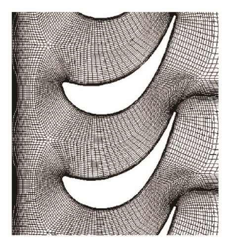
This mesh configuration considers the calculation and comparison of turbulence model and combines it with the near wall modified function with low Reynolds numbers in order to effectively offset the interference that occurs in the internal flow field to improve the near wall computational grid’s deficiencies.
Therefore, the distance of the first cell layer from the blade surface was 0.001 mm; the added blended wall function implemented in the turbulence model leads to the boundary layer at the solid walls with further refinement by y+ value; this gave a value of the dimensionless wall-distance y+ ≈ 1.
The computation of entire mesh used a three-level full multigrid method for convergence acceleration. Our simulation results for such a mesh configuration showed a difference of mass flow in the inlet and outlet plane of less than about 0.02%. This validation showed a very good quality of the applied mesh configuration.
3.4. Operating Conditions of the Turbine Stage
The numerical calculation of the flow in the turbine stage was realized for its optimum operating point deduced from the experimental data, all relevant data for inlet and outlet are summarized in Table 4. The total-static pressure ratio .
| Notation | Unit | Value |
|---|---|---|
| [Pa] | 142857 | |
| [Pa] | 140812.5 | |
| [Pa] | 100000 | |
| [K] | 323.1 | |
| [K] | 321.772 | |
| Tu | [%] | 1 ⋯ 2% |
| h/SBi | [—] | 2.1le |
| [m/s] | 51.657 | |
| [m/s] | 0.0 | |
|
|
[m/s] | 0.0 |
| [kg/s] | 4.93 | |
| n | [rpm] | 7190 |
| R | [J/(kgK)] | 287.14 |
| ρ | [kg/m3] | 1.53 |
The applied 3D calculations of total stage efficiency with axial gap 6.5 mm were performed for two different ranges of the run number ν.
(i) Run Number ν in the Range 0.3 to 0.6. In this range of the run number, the pressure ratio Π = 0.7 remained constant, so the enthalpy change remained also constant. But the rotational speed was changed for different operating points. The applied data are shown in Table 5.
| ν [—] | 0.314 | 0.366 | 0.455 | 0.484 | 0.539 | 0.550 | 0.563 | 0.578 |
|---|---|---|---|---|---|---|---|---|
| n [rpm] | 4113 | 4790 | 5955 | 6326 | 7046 | 7190 | 7366 | 7567 |
(ii) Run Number ν in the Range 0.6 to 0.9. In this range of the run number, the rotational speed was no longer changed, but the reduced rotational speed was maintained at a constant value 4000. However, on the contrary, the pressure ratio was changed by various static pressures on entry. This data is shown in Table 6. Therefore, the enthalpy or the mass flow is also changed.
| ν [—] | 0.600 | 0.612 | 0.672 | 0.704 | 0.778 | 0.800 |
|---|---|---|---|---|---|---|
| [Pa] | 134543 | 132957 | 126460 | 123753 | 118911 | 117797 |
4. Results and Discuss
4.1. Validation of Numerical Results
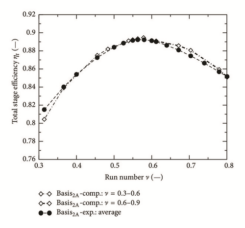
For the operating points in both Tables 5 and 6, the turbine stage was computed with a real axial gap 6.5 mm, the results are shown in Figure 5. It shows that the stage efficiency is a function of the run number ν. The run number ν has been divided into two ranges for the computations of the stage efficiency. In the range of the run number between 0.3 and 0.6, the stage efficiency of the radial blade Basis2A agrees very well with the experimental data. However, the computations of this radial blade in the range between 0.6 and 0.9 also show a pretty good consistency outside the range between 0.65 and 0.85 since in this range only a deviation of about 0.3 occurs. The accuracy of presented numerical results can therefore be validated by this comparison result clearly.
4.2. Effect on the Meridional Streamlines
The form of meridional streamlines is essentially determined by the radial blade forces acting on the flow, mainly the centrifugal force and the radial pressure gradient ∂p/∂r. In the familiar stage design according to the free vortex law (approximately it is realized in the Basis2A-stage), these are balanced so that no radial displacement of streamlines occurs, as in Figure 6.
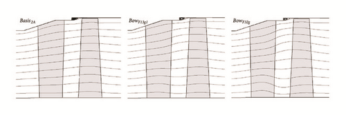
The type of bow applied in two guide vanes presented here will create additional radial blade forces acting towards the hub and the casing in the sidewall regions. The balance of radial forces and the radial flow displacement will vary to extent in the circumferential direction too and then a 3D-flow field will be formed really. A simplified presentation is shown in Figure 6; a circumferential averaged flow over the pitch is calculated and applied to the calculation of meridional streamlines in this figure; a similar result would be achieved by a 2D-calculation of the flow field.
By the comparison with both curved guide vanes of the meridional flow in Figure 6, it shows that the radial displacement of streamlines towards the guide vane ends has the same effect of bow. The bow-effect for the vane BowF32g, whose inclination (bow) angles ε have more than double the value of the vane BowF13g1, is more distinct. The radial deflection tapers off in the gap between stator and rotor and is concentrated in the outlet part of guide vanes, where the radial blade force has its full effect. Consequently, the deflection of streamlines towards the sidewall will cause a deceleration of the axial flow velocity in the middle part of guide vanes, which can be seen under the increased distance of streamlines compared with the radial guide vane Basis2A; such an effect for the velocity distribution over the blade height is important.
4.3. Radial Blade Forces Produced by Blade Curvature
4.3.1. Treatment and Modeling of the Radial Blade Force
Blading designed according to standard principles with radial stacking line produces blade forces acting essentially in circumferential and axial directions, and the radial component remains very small. In addition, the inclined and curved guide vanes develop the radial blade force, which can attain the same magnitude as the circumferential and axial components and therefore enter into the radial equilibrium as important terms, which influences the flow field.
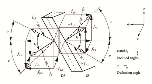
A schematic representation of three-dimensional blade force and an element angle of inclined or curved guide vane are represented as a definition of balance direction in Figure 7 at the blade trailing edge. It shows that on the flow the reaction blade forces of guide vane are exerted on the pressure side and the suction side , respectively. They act on the blade surface perpendicularly and have different values on both sides.
4.3.2. Distribution of the Resultant Radial Blade Force
- (i)
The region for the radial blade force is about equal to the region of blade zones for bow (ca. 40% of blade height on both ends).
- (ii)
The radial blade force is increasing in the inclination (curved) angle ε as well as on the same blade in direction of the increasing bow as from blade to blade with increased bow.
- (iii)
The radial blade force tapers off in the proximity of sidewall, even if the inclination (curved) angle increases there. This is probably due to reduced aerodynamic loading of profiles there.
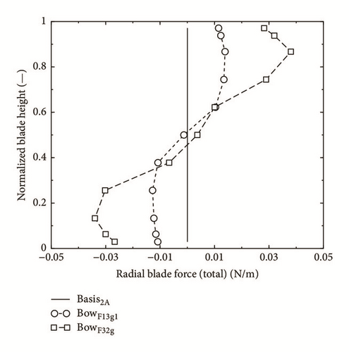
The distributions and magnitude of the radial blade force correspond directly with the deflection of meridional streamlines in Figure 6, introducing the radial blade force in the equation of radial equilibrium; their form can be calculated quantitatively.
4.4. Effect of the Blade Curvature on the Static Pressure Distribution at the Profiles
The aerodynamic blade forces and their components result from the static pressure on the profile and the geometric orientation of its surface elements. The pressure distribution itself is, also, of great importance for the flow over the profile, especially the boundary layer and its development. Boundary layer thickness, transition, and eventually separation depend to a great deal on the pressure distribution. It is of great interest therefore how the inclination and curvature of a blade influence the pressure distribution.
4.4.1. Aerodynamic Load of the Blade Profiles
If the static pressure distribution over a profile is presented over the axial chord, as in Figure 9, the area circumscribed by the pressure side and the suction side curve is directly proportional to the circumferential (or working) total force of the blade profile; the difference between the two curves at an axial station describes the local aerodynamic loading and the form, especially of the suction side curve, is important for the boundary layer development and hence for the profile loss.
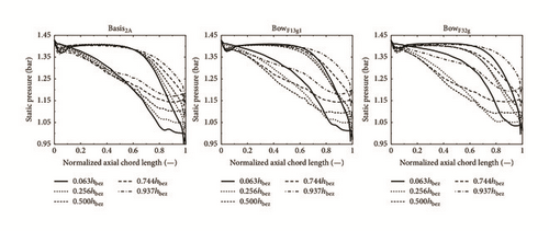
Figure 9 shows the static pressure distributions over the profile sections at different height positions for the three guide vanes treated here. Two curves are near the sidewalls (0.063 and 0.937 normalized blade height), two are in the middle of the bow zones (0.256 and 0.744), and one is in the middle of the blades (0.5). It is obvious that, because of the radial pressure gradient between stator and rotor, the outlet pressure increases with increasing blade height, as visible in Figure 9 for all three stators. Noteworthy is the decrease in aerodynamic loading (circumscribed area) towards the sidewall with increasing bow, especially in the hub area. Finally remarkable and quite unexpected is the fact that the pressure distributions of the profiles close to the sidewalls of the curved vanes are distinctly deformed, so that the aerodynamic loading is not only reduced, but also displaced towards the trailing edge and acceleration on the suction side is delayed. This effect seems, too, to be proportional to the degree of curvature.
4.4.2. Pressure Distribution on the Suction Side
The variation of the pressure distribution, especially on the suction side, by the blade curvature is shown in Figure 9 for several distinct profile sections. It can also be demonstrated in a continuous way by a graph of the pressure distribution on the suction side over the blade height as shown in Figure 10 for the three vanes. The isobaric lines of the radial basis vane extend essentially in radial direction over the blade height; the peaks near the trailing edge are a result of a slight overspeed on the profile. In direct proximity of the sidewalls they bow a little downstream. This somewhat more distinct effect near the casing is probably due to the conical contour.
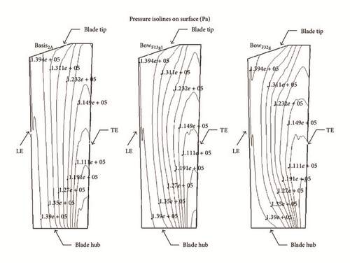
Blade curvature now effects a clear displacement of the isobars in downstream direction near both sidewalls, more pronounced by stronger blade curvature, and resulting from the downstream movement of the blade loading described in Section 4.4.1. While the local inclination of the blade produces for the bulk of the flow an additional force directed towards the sidewalls, as shown before, it creates, somewhat unexpected, near the suction surface of the blade a component of the pressure gradient, which is directed towards the middle of the blade. As is well-known the low energy fluid of the secondary flow accumulates in the corner between suction side and sidewall. This static pressure component directed towards the center of the blade might be able to transport part of the low energy fluid out of the suction corner and might be assisted by the obtuse angle between sidewall and suction side resulting from the blade inclination. Here is a reason for the repeatedly observed reduction of secondary loss by bowing of blades.
4.5. Effect of the Curvature on the Vane Outlet Angle
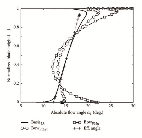
Since the inclination of the blade changes the aerodynamic loading as well as the circumferential component of the blade force the turning of the flow (e.g., [37]), that is, the outlet angle of the vane, will be influenced, too (e.g., [38]). Figure 11 shows the distribution of the flow outlet angle, averaged over one pitch, over the blade height. The angle of the radial blade is equal to the value according to the sine-rule (effective angle) over most of the blade height. The curved blades exhibit clear underturning over 20% of the blade length at both ends, intensified by higher blade inclination, which is certainly due to the reduced blade loading in these areas. Not so obvious is the explanation for the overturning by 2 to 4 deg. in the middle zone. Probably it can be attributed to the deceleration of the axial flow velocity in this area because of the deflection of the flow towards the sidewalls.
4.6. Effect of the Blade Curvature on the Loss Coefficient of the Vanes
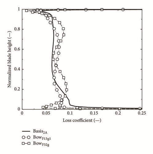
The changes of the loss distribution and magnitude will be due to a combination of influences, as different development of profile boundary layer because of different pressure distribution, oblique movement of boundary layer on inclined parts of the blade, different secondary flow, and so forth. Finally the well-known deficiencies of Navier-Stokes-solvers in calculating dissipation correctly must not be forgotten.
| Notation |
|
[%] |
|---|---|---|
| Basis2A | 0.0767 | — |
| BowF13g1 | 0.0744 | −2.943 |
| BowF32g | 0.0782 | +2.005 |
5. Effects of the Vane Curvature on the Rotor Flow
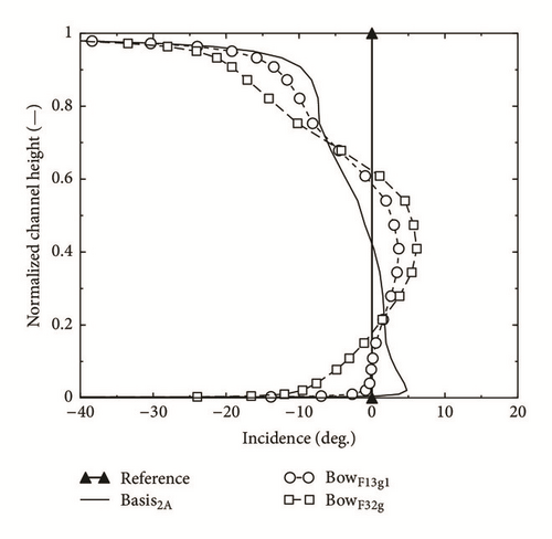
Any modification of the stator of a turbine stage, which changes the flow field at its outlet, will directly influence the flow entering the rotor and therefore its aerodynamic effectivity (e.g., [40–45]). In our case the curvature of the stator vanes changes the outlet angle and the axial flow velocity; together they define in the velocity triangle the relative inlet flow angle for the rotor. The difference between aerodynamic inlet angle and the geometric inlet angle of the rotor blade, the incidence angle, is of central importance for the aerodynamic action of the rotor blade profiles. High positive inlet angles cause an aerodynamic overload of the profile and high loss. Negative incidence angle may result in adverse profile pressure distribution and increased loss, too.
Figure 13, showing the rotor incidence angles for the three cases, makes it clear that the basis stage, which had been conceived for the experiments at the department for power, nuclear turbine construction, and aircraft engines of State St. Petersburg Technical University, had already not been designed in an optimum way, since in the top half of the rotor blade a considerable negative incidence prevails. The loss distribution, presented in Figure 14, shows however that this design seemed not to have a negative consequence. The influence of the vane bow on rotor incidence in Figure 13 results directly from the variation of the vane outlet angle α1. Therefore its values move towards negative in the two sidewall areas and towards positive on the middle of the blade. Interesting, though not quite easy to explain, is the reaction of the rotor loss coefficient on the bow of the stators. The remarkable reduction of the loss coefficient in the lower half of the blade is not directly attributable to the variation of the incidence. Probably it results from a reduction of profile loss as well as secondary loss and would require a detailed study of the loss characteristics of the rotor profiles in function of the incidence. Values of the integrated loss coefficient of the rotor for the three cases in question are given in Table 8.
| Notation |
|
[%] |
|---|---|---|
| Basis2A | 0.0814 | — |
| BowF13g1 | 0.0771 | −5.346 |
| BowF32g | 0.0728 | −10.531 |
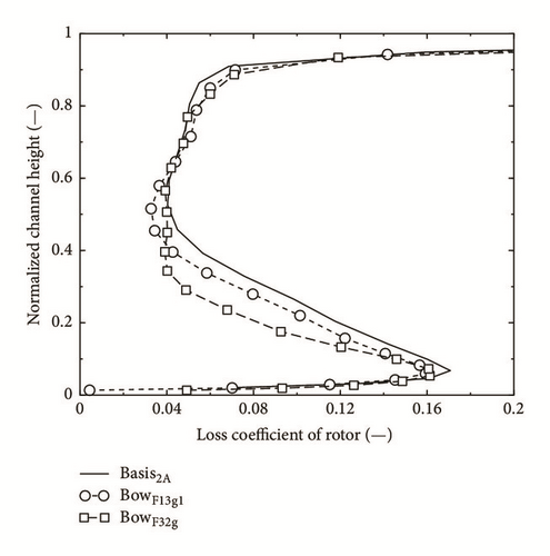
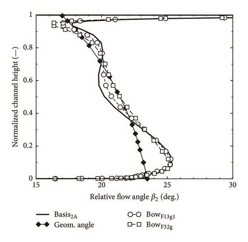
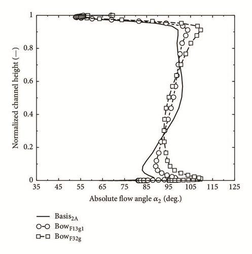
As could be expected from Figure 14 they show a distinct reduction of loss for the cases with bow vanes. Finally the rotor outlet angle β2 is presented in Figure 15. Since the outlet angle of turbine blade profiles is within a certain range independent of the inflow angle, it could be expected that the β2-distribution is little influenced by the bow of the vanes. It shows the familiar underturn near the wall and the overturn directly at the wall, both due to secondary flow, in a pronounced way near the hub and less clear near the tip, where directly at the wall the clearance flow predominates. The influence of the vane bow is small. The absolute flow angle α2 behind the rotor is defined not only by β2, but via the velocity triangle by the axial velocity, too. This is, as we have seen, influenced considerably by the curvature of the vanes and this influence is still sensible behind the rotor. Therefore, as Figure 16 shows, the flow angle α2 can be changed by 10 deg. and more through the vane bow, even if β2 differs by one or two deg. only for the different cases.
6. 2D-Modeling of the Flow Deflection
6.1. Correction Function for the Exit Flow Angle of Curved Blade
6.1.1. Correction Function Based on Experimental Data
6.1.2. Correction Function for Vanes with High Curvature
6.2. Validation of the Correction Function
Since the numerically investigated vanes have been developed by tangential displacement of the unvaried profiles of the radial basis stator their effective exit flow angle distribution is identical with that of the stator Basis2A. The geometry and hence the effective flow angle distribution of the stator Bow2B, for which experimental data are available, are quite different. The exit flow angle distribution of the two curved stators Bow2B and BowF32g has been calculated with the correction function described above. The values of the geometrical and empirical coefficients that have been used are shown in Table 9. Further validations of other blade types from the numerical simulation are carried out in this investigation, respectively (not treated here in detail).
| Notation | Bow2B | BowF32g | K |
|---|---|---|---|
| n | 3 | 3 | k |
|
|
13 | 13 | k |
|
|
20 | 15.35 | a |
|
|
1.195 | 1.085 | a |
Figure 17 shows the results for the vane Bow2B, which comprises inclination mainly in the lower half. The resulting exit flow angle differs sensibly in this region from the sine-rule value; the corrected angle according to (25) and the coefficients in Table 9 agree well with the experimental and the values of the 3D-computation. Because of the moderate degree of inclination the correction in the simplified form of (23) with a constant value of k = 0.435 would render good results.

Figure 18 shows results for the vane BowF32g with considerable curvature on both ends. The corrected angles according to (25) with the coefficients in Table 9 represent the results of the 3D-simulation very well in both sidewall regions. Since the correction model cannot take care of the redistribution of the aerodynamic blade load into the middle of the blade the reduction of the flow angle in that region will not be correctly described (see Figure 11). The validation of this correlation is tested at present likewise for the throughflow calculation by the TU St. Petersburg as well as industry in St. Petersburg.
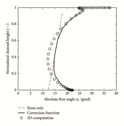
Because the sine-rule is valid for two-dimensional cascade flow, the exit flow angle distribution will show some deviations from these values in the sidewall zones of radial blades, too. Secondary flow will cause underturning when approaching the sidewall and overturning in its direct proximity; radial clearance will cause considerable underturning. These deviations from the sine-rule values can be calculated by specific flow models, described, for example, in [47], and then introduced in our correction procedure instead of the effective flow angle α1 for improved modeling. In Figure 17 these influences are visible to some extent. A distinct tangential curvature, however, will render flow angle modifications, which surpass the secondary flow influence considerably, as is clearly visible in Figure 18.
7. Conclusions
Results of numerical 3D flow simulations of an axial turbine stage with radial and two different curved guide vanes are presented. The curved guide vanes are developed by tangential displacement of the profiles of the radial vane. The simulation procedure was validated with the aid of experimental data, not presented here.
The guide vanes with curvature on both ends form an obtuse angle between suction side and sidewall. They generate radial pressure forces, which displace the fluid flow towards the sidewalls. The axial velocity is increased there as well as the exit flow angle. The pressure distribution of the blade profiles is deformed, so that the aerodynamic loading is shifted backwards. This produces a radial component of the pressure gradient on the suction side directed towards the middle of the blade. This phenomenon probably promotes a displacement of the secondary flow and a reduction of the secondary loss. All effects are intensified by increased blade inclination and extended area of the curvature.
The modification of vane exit angle and axial velocity distribution will cause changes of the incidence to the rotor up to 10° and more, so that adaption of the rotor geometry, when applying curved stators, seems necessary.
In order to render the flow calculation of curved stators feasible by the widespread 2D-methods (through flow method) a radial force model and an exit angle model for curved stators were developed. It departs from the familiar sine-rule and comprises a correction function, which depends mainly on the local inclination angle ε of the vane. General coefficients permit the adaption to different blade curvatures. Further research by numerical simulation, finally validated by experiments, which is extended to other profile types, profile modifications in the inclined zone, other types of curvature, and so forth, will probably lead to optimum forms of bow vanes with reduced secondary loss and increased efficiency.
Symbols
-
- a:
-
- Exit channel width
-
- c:
-
- Flow velocity in abs. system
-
- :
-
- Vector of the force
-
- hs:
-
- Specific enthalpy
-
- h:
-
- Blade and channel height
-
- Δhs:
-
- Change of the isentropic spe. enthalpy
-
- i:
-
- Incidence
-
- k:
-
- Coefficient
-
- :
-
- Mass flow rate
-
- n:
-
- Speed in normal direction
-
- p:
-
- Pressure
-
- r:
-
- Radius
-
- R:
-
- Gas constant
-
- S:
-
- Blade chord length
-
- T:
-
- Temperature
-
- Tu:
-
- Turbulence degree
-
- α:
-
- Flow angle in the abs. system
-
- β:
-
- Flow angle in the rel. system
-
- Δ:
-
- Difference
-
- δ:
-
- Curving angles of meridian streamlines
-
- δsp:
-
- Gap width of tip clearance
-
- ε:
-
- Curvature angle of blade stacking line
-
- ζ:
-
- Loss coefficient
-
- κ:
-
- Specific heat ratio
-
- ν:
-
- Angle of the meridional stream surface
-
- ρ:
-
- Flow density
-
- Π:
-
- Pressure ratio of turbine stage.
Indices
-
- 0,1, 2:
-
- Exp. measured positions
-
- aus:
-
- Outlet of the stage
-
- ax:
-
- Axial
-
- bez:
-
- Normalized
-
- Bi:
-
- Bitangent
-
- DS:
-
- Pressure side
-
- ein:
-
- Inlet of the stage mesh
-
- eff:
-
- Effective according to sine-rule
-
- G:
-
- At the casing
-
- int:
-
- Integration
-
- is:
-
- Isentropic
-
- k:
-
- Curvature zone and coefficient
-
- la:
-
- Rotor
-
- le:
-
- Stator
-
- m:
-
- Meridional comp. and middle value
-
- N:
-
- At the hub
-
- r:
-
- Radial component
-
- rech:
-
- Computation
-
- s:
-
- Static
-
- sp:
-
- Gap losses or gap
-
- SS:
-
- Suction side
-
- t:
-
- Total
-
- z:
-
- z-axial component
-
- φ:
-
- Circumference component.
Conflicts of Interest
The author declares that they have no conflicts of interest.
Acknowledgments
This study described here was supported by the Ministry of Science and Technology and the National Science Council (MOST104-2221-E-035-052; MOST103-2632-E-035-001-MY3; MOST103-2221-E-035-064; NSC102-2221-E-035-029; NSC101-2221-E-035-010) and was completed due to the support of Professor W. Riess and Professor J. Seume of the Institute for Turbomachinery and Fluid Dynamics of Leibniz University of Hannover. The author is very grateful for this aid and wants to thank their continuously encouragement and cooperation as well as their helpful discussions to this work for the writing. The basic blade data and experimental results were completed and available due to the support of Professor Lapschin of the Department for Power, Nuclear Turbine Construction and Aircraft Engines of State St. Petersburg Technical University.


