Analysis of Tensegrity Structures with Redundancies, by Implementing a Comprehensive Equilibrium Equations Method with Force Densities
Abstract
A general approach is presented to analyze tensegrity structures by examining their equilibrium. It belongs to the class of equilibrium equations methods with force densities. The redundancies are treated by employing Castigliano’s second theorem, which gives the additional required equations. The partial derivatives, which appear in the additional equations, are numerically replaced by statically acceptable internal forces which are applied on the structure. For both statically determinate and indeterminate tensegrity structures, the properties of the resulting linear system of equations give an indication about structural stability. This method requires a relatively small number of computations, it is direct (there is no iteration procedure and calculation of auxiliary parameters) and is characterized by its simplicity. It is tested on both 2D and 3D tensegrity structures. Results obtained with the method compare favorably with those obtained by the Dynamic Relaxation Method or the Adaptive Force Density Method.
1. Introduction
Cable networks [1–3] and tensegrity structures [4] are different from conventional structures, such as spatial steel frames or space steel trusses, in that they are lightweight structures with members which transmit only tension (cables and strings) or elements which transmit compression (bars before buckling). In this article, we are studying only the behavior of tensegrity structures. These structures are usually defined as planar or spatial trusses with a discontinuous set of members under compression, inside a continuous network of members under tension. The word tensegrity is an artificial word and it combines the words “tension” and “integrity.” This word was coined several decades ago. Professor Fuller, in the United States, was essentially involved in the invention of this technical word. In one of his last books, Fuller described the compression members as “islands of compression in a sea of tension” [4]. Using the same concept, Emmerich [5] presented, in France in 1963, his own tensegrity patent. Snelson, one of Fuller’s students, describes this type of structures as “continuous tension and discontinuous compression structures” [6].
Pretension, applied by means of tension members, plays an essential role in the structural behavior of the tensegrities. For the design of such structures, their stability is investigated under both static and dynamic loads. During the last decades, many methods have been proposed for the analysis of the tensegrities. One of the most important methods is the Dynamic Relaxation Method (DRM) which was used in this research for checking the numerical results obtained with the numerical scheme proposed in the present work. DRM is one of the classical techniques. It belongs to the family of methods under the title of three-term recursive formulae. It is an iterative procedure which is based on the fact that a system undergoing damped vibration, excited by a constant force, ultimately comes to rest in the displaced position of static equilibrium, obtained under the action of the constant force. One of the numerous first papers, written by pioneers of this method, is that of Papadrakakis [7] which proposes an automatic procedure for the evaluation of the iteration parameters and it is mentioned here (without underestimating the importance of other works in this domain) as an example of an article which presents in a strict, clear, and academic manner the way of implementing this numerical procedure. Recent research, performed in the domain of tensegrities, has given some new important techniques. However, a general review of the older and of the recent numerical schemes, developed in this area, is out of the scope of the present paper. Juan and Mirats Tur present an excellent review in their work [8] of the basic issues about the statics of tensegrity structures. Among the new methods, presented in literature during the last few years, is that of Zhang and Ohsaki [9] which is also considered in the present research for comparison purposes. Their method is an Adaptive Force Density Method (AFDM). It first finds a set of axial forces compatible with a given structure and then estimates the corresponding nodal coordinates under equilibrium conditions and constraints.
The technique implemented in the present work is a force density method which belongs to the class of the Equilibrium Equations Methods with Force Densities (EEMFD). With this method, the system of equilibrium equations is created by considering the equilibrium of forces in all the joints. The redundancies are treated by employing Castigliano’s second theorem which gives the additional equations required to have a solution [10]. The partial derivatives, which appear in the additional equations, are numerically replaced by statically acceptable internal forces acting along the members. Also, the properties of the matrix of the system of linear equations are exploited because they give a strong indication of the stability of the structure.
- (1)
Joints are frictionless but their mass is considered in calculations unless otherwise specified.
- (2)
The self-weight of a member (for structures within earth’s gravity field) is not neglected unless otherwise specified. It is equally distributed at its ends.
- (3)
Live loads and pretensions on a member are transferred to the joints. They are equally distributed at the ends of the member.
- (4)
Displacements on the joints and deformations of the members of the structure are relatively small compared with the dimensions of the structure.
- (5)
The axial force carried by a member is constant along its length.
- (6)
The materials used, for all members of the structure, obey Hooke’s Law for loadings below the yield stress.
The outline of the rest of this paper is as follows: in Section 2 we develop the formulation of a Comprehensive Equilibrium Equations Method with Force Densities (CEEMFD) and in Section 3 we discuss the treatment of redundancies and we investigate the stability in this type of structures. In Section 4, some applications of the method are presented on planar and on spatial tensegrity structures. The article ends with Section 5 in which conclusions and proposals for future work are given.
2. A Comprehensive Equilibrium Equations Method with Force Densities

3. Redundancies, Numerical Representation of Castigliano’s Second Theorem, and Stability
The values of the elements of matrix A in (8) depend directly on the values of the coordinates of the nodes. For planar problems it has dimensions 2N × (Nb + 2Ns) and for spatial structures it is of dimensions 3N × (Nb + 3Ns). For the statically determinate structures [10] and after inserting in the set of equations (8) the known values of reactions on the supports, matrix A is reduced to a square matrix Ke of dimensions 2N × 2N, in two dimensions and 3N × 3N in three dimensions. Its properties, as a square matrix, give important information about the stability of the form of the structure under study. So, for statically determinate structures, the set of linear equilibrium equations (8) has a solution if and only if det|Ke | ≠ 0. Other equivalent conditions concerning square matrix Ke, which secure the existence of a solution are given in many references about numerical analysis (e.g., [11]). If matrix Ke has a determinant equal to zero then, most probably, the structure is unstable.
- (1)
Matrix Ke has a rank ρ equal to the rank of the augmented matrix (Ke/γ).
- (2)
The determinant of the square matrix Ke is not equal to zero; that is, det|Ke | ≠ 0.
- (3)
The inverse of the square matrix Ke exists and gives .
- (4)
The number nind of linearly independent rows or columns of matrix Ke is equal to ρ.
4. Numerical Examples
4.1. The X-Shape 2D Tensegrity Structure
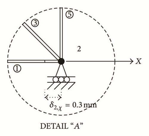
One of the fundamental tensegrity configurations, used by Fuller [4] and Snelson [6] to create more complicated stable structures, is the X-shape 2D tensegrity truss with N = 4 nodes (Figure 2(a)). Skelton [12] studied analytically this truss which has four steel cables (elements 1, 2, 5, and 6) and two rods made of an aluminum alloy (members 3 and 4). The technical characteristics of the cables and rods are presented in Table 1. The weight of each joint is G = 0.01 kN. No other external loads are applied. Cable 1 in our example is shorter than the required length. During construction one end of the cable is connected to joint 1 and the other is extended by δ2,χ = 0.3 mm to meet joint 2, as it is explained in the exaggerated detail “A” (Figure 2(b)), which is not to scale.
| Type of member | Outer diameter do (mm) | Inner diameter di (mm) | Cross-sectional area A (mm2) | Moment of inertia I0 (m4) | Specific weight γ (kN/m3) | Young’s modulus E (GPa) | Yield stress σy (MPa) |
|---|---|---|---|---|---|---|---|
| Tension members (steel cables) | 8 | — | 50.24 | — | 78 | 210 | 360 |
| Compression members (aluminum rods) | 40 | 37 | 181.34 | 3.36 × 10⁻⁸ | 26.50 | 70 | 260 |
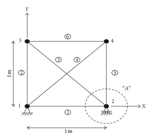
The complete set of linear equilibrium equations (8), for this problem, consists of 2N = 8 equations. It has Nb + Nur − 2N = 1 parametric solutions. We say that the structure has a redundancy equal to 1. Rod 1 is chosen as the redundant member of the structure (Figure 2(a)). Using expression (19) with mm and considering that Q(1) = L1,2q1,2 we obtain the additional linear equation −0.0346 + 7.3246q1,2 = 3.16512 which gives q1,2 = 0.4368 kN/m. Thus, the value of the force on this element is F1,2 = 0.4368 kN. Also, this equation is added to equations (12) to give a complete system of linear equations. Expanded matrix Ke of the final system of equations has a nonzero determinant. The results for all forces on the members and the reactions on the supports are tabulated in Table 2 together with those obtained with the DRM. The CEEMFD and the DRM give results which are comparable. However, the CEEMFD is proved to be faster than the DRM (Table 2) because it is a direct method (no iterations are necessary). Also, Table 3 presents the value of the vertical displacement δtop,y of joint 3, obtained by the method, the DRM and the analytic approach proposed by Skelton [12] for the same problem. The results for δtop,y, with all three methods, are the same. By comparing the results obtained in [2], for an analogous problem of the same geometry, with those obtained in the present work (Tables 2 and 3), one may observe that the numerical results in the current work have values which are almost equal to 10% of the corresponding values obtained in solving the analogous problem proposed in [2]. This difference was expected due to the linearity existing in both problems and due to the fact that the values of , in the two cases, differ by 90%. The materials used, in both cases, had slightly different properties. It is also verified that the structure passes axial yield and Euler buckling criteria.
| Force density qi,j | Value of qi,j with CEEMFD (kN/m) | Value of qi,j with DRM (kN/m) | Length Li,j of a member (m) | Value of force Fi,j with CEEMFD (kN) | Value of force Fi,j with DRM (kN) | Reaction force on a support | Value of reaction with CEEMFD (kN) | Value of reaction with DRM (kN) | CPU time with CEEMFD (sec) | CPU time with DRM (sec) |
|---|---|---|---|---|---|---|---|---|---|---|
| q1,2 | 0.4368 | 0.4367 | 1.0000 | 0.4368 | 0.4367 | R1,x | 0 | 0 | 0.02 | 2.03 |
| q1,3 | 0.4195 | 0.4196 | 1.0000 | 0.4195 | 0.4196 | R2,x | 0 | 0 | ||
| q1,4 | −0.4369 | −0.4368 | 1.4142 | −0.6178 | −0.6177 | R1,y | 0.0346 | 0.0345 | ||
| q2,3 | −0.4369 | −0.4368 | 1.4142 | −0.6178 | −0.6177 | R2,y | 0.0346 | 0.0345 | ||
| q2,4 | 0.4195 | 0.4196 | 1.0000 | 0.4195 | 0.4196 | |||||
| q3,4 | 0.4368 | 0.4367 | 1.0000 | 0.4368 | 0.4367 | |
| CEEMFD | DRM | Skelton’s analytic approach [12] | |
|---|---|---|---|
| Vertical displacement of joint 3 (in mm) | 0.04 | 0.04 | 0.04 |
4.2. A Weightless 2D Tensegrity Structure
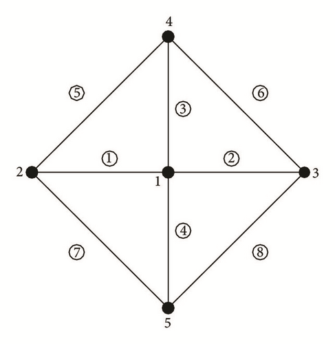
Zhang and Ohsaki [9] use the Adaptive Force Density Method (AFDM) to solve a weightless two-dimensional tensegrity structure which is without any support and out of any gravitational field (Figure 3). This structure has four cables (elements 1, 2, 3, and 4) and four struts (members 5, 6, 7, and 8). The steel cables and the aluminum rods have the same stiffness which in the current work is chosen to be (EA)r = (EA)c = 12694 kN, without changing the generality of the problem. Also, the aluminum rods have a hollow cross section with a moment of inertia, about any diameter, equal to Ir = 3.36 × 10⁻⁸ m4. The only load on the structure is the pretension on cable 1 which is equal to 1 kN (Figure 3). In order to use the CEEMFD we introduce, temporarily, two auxiliary supports at joints 2 and 5 on which there are no reactions (it is as if they do not exist). These supports will only help to define the degree of redundancy. The complete set of linear equilibrium equations (12), for this problem, consists of 2N = 10 equations. It has Nb + Nur − 2N = 1 parametric solutions. Thus, the structure has a redundancy equal to 1. Cable 1 is chosen as the redundant member. In using the CEEMFD the additional linear equation, which is required in order to find the unknowns, is −6.8284 + 6.8284q1,2 = 0, from which one obtains q1,2 = 1 kN/m. From the form of matrix Ke it is verified that the structure is stable (i.e., |Ke | ≠ 0). The same problem is also solved with the DRM and the AFDM [9]. The results are presented in Table 4. One can see that the CEEMFD and the AFDM [9] give results which are comparable and more accurate than those obtained with the DRM. Exactly the same results were obtained and the same observation was made in [2] for an analogous problem of the same geometry but with different material properties. Thus, for this specific problem the results are independent of the material properties. It is also verified that the structure passes axial yield and Euler buckling criteria.
| Force density qi,j | Value of qi,j with CEEMFD (kN/m) | Value of qi,j with AFDM [9] (kN/m) | Value of qi,j with DRM (kN/m) | Length Li,j of a member (m) | Value of Fi,j with method CEEMFD (kN) | Value of Fi,j with method AFDM [9] (kN) | Value of force Fi,j with DRM (kN) |
|---|---|---|---|---|---|---|---|
| q1,2 | 1.00000000 | 1.00000000 | 1.00000072 | 1.00000000 | 1.00000000 | 1.00000000 | 1.00000072 |
| q1,3 | 1.00000000 | 1.00000000 | 1.00000072 | 1.00000000 | 1.00000000 | 1.00000000 | 1.00000072 |
| q1,4 | 1.00000000 | 1.00000000 | 1.00000072 | 1.00000000 | 1.00000000 | 1.00000000 | 1.00000072 |
| q1,5 | 1.00000000 | 1.00000000 | 1.00000072 | 1.00000000 | 1.00000000 | 1.00000000 | 1.00000072 |
| q2,4 | −0.50000000 | −0.50000000 | −0.50000036 | 1.41421356 | −0.70710678 | −0.70710678 | −0.70710729 |
| q2,5 | −0.50000000 | −0.50000000 | −0.50000036 | 1.41421356 | −0.70710678 | −0.70710678 | −0.70710729 |
| q3,4 | −0.50000000 | −0.50000000 | −0.50000036 | 1.41421356 | −0.70710678 | −0.70710678 | −0.70710729 |
| q3,5 | −0.50000000 | −0.50000000 | −0.50000036 | 1.41421356 | −0.70710678 | −0.70710678 | −0.70710729 |
4.3. A Cantilever 2D Tensegrity Beam
In this subsection, a problem of a cantilever planar tensegrity beam is investigated (Figure 4). This structure is supported at the two leftmost nodes 1 and 3 and loaded with a unit vertical force acting at the top-right node 10 (Figure 4). This type of structure was well investigated by Masic et al. [13] who used a nonlinear large displacement model to find its static response and to make a design with optimal mass-to-stiffness ratio. In the present work, no optimization was made. The CEEMFD was simply implemented on this problem, by considering the same geometry proposed by Masic et al. [13] and by arbitrarily choosing the material properties for the rods and the cables. So, this structure has thirteen steel cables (elements 1, 2, 3, 4, 5, 8, 9, 12, 13, 16, 17, 20, and 21) and eight aluminum struts (members 6, 7, 10, 11, 14, 15, 18, and 19). The technical characteristics of the cables and rods are given in Table 5. According to the method, along each one of cables 1, 2, 3, and 4 a pair of opposite axial forces, of value 1 kN, is acting each time. Each one of these forces is pushing an end node. Also, a gap exists between the right-end on each one of these members and its nearest joint. This gap is the same for all the four members and is equal to 54.2640/(EA)c or 10 mm (0.4 in. approx.). The truss is a statically indeterminate structure with a degree of redundancy Nr = Nb + Nur − 2N = 4.
| Type of member | Outer diameter do (mm) | Inner diameter di (mm) | Cross sec. area A (mm2) | Moment of inertia I0 (m4) | Specific weight γ (kN/m3) | Young’s modulus E (GPa) | Yield stress σy (MPa) |
|---|---|---|---|---|---|---|---|
| Tension members (steel cables) | 5.74 | — | 25.84 | — | 78 | 210 | 480 |
| Compression members (alum. rods) | 77 | 75 | 238.76 | 1.72 × 10⁻⁷ | 26.50 | 70 | 260 |
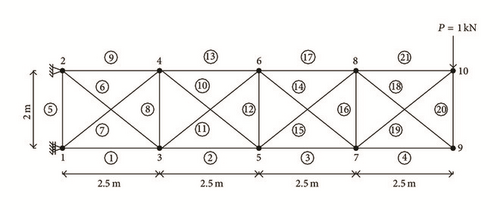
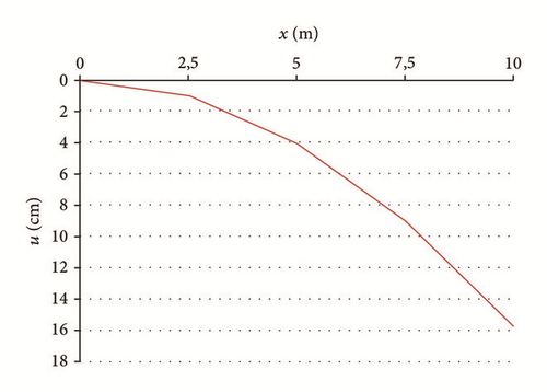
Tensions in cables 1, 2, 3, and 4 are chosen as redundancies. Matrix Ke is well-conditioned. The results with CEEMFD are presented in Table 6 together with those of the DRM which was also implemented to this problem. The two methods give results which are comparable. Also, Table 7 gives the values of the vertical displacement at joints 4, 6, 8, and 10 obtained by the method and the DRM. The two sets of results are again comparable. One may visualize the deformed shape of this structure by observing the graph in Figure 5, which presents the displacements along its upper side. It is also verified that the structure passes axial yield and Euler buckling criteria.
Value of qi,j with CEEMFD (kN/m) CPU time = 0.07 sec |
Value of qi,j with DRM (kN/m) CPU time = 8.25 sec |
Length Li,j of a member (m) | Value of force Fi,j with CEEMFD (kN) | Value of force Fi,j with DRM (kN) | Value of stress σi,j with CEEMFD (MPa) | |
|---|---|---|---|---|---|---|
| Force density qi,j | ||||||
| q1,2 | 0.240633 | 0.240613 | 2.5000 | 0.601583 | 0.601533 | 23.2811 |
| q2,5 | 0.651541 | 0.651521 | 2.5000 | 1.628852 | 1.628802 | 63.0361 |
| q5,7 | 1.196278 | 1.196278 | 2.5000 | 2.990696 | 2.990696 | 115.7390 |
| q7,9 | 1.966444 | 1.966444 | 2.5000 | 4.916110 | 4.916110 | 190.2519 |
| q1,3 | 2.461283 | 2.461415 | 2.0000 | 4.922566 | 4.922830 | 190.5018 |
| q2,3 | −1.861511 | −1.861511 | 3.2016 | −5.959814 | −5.959814 | −24.9615 |
| q1,4 | −2.454204 | −2.454336 | 3.2016 | −7.857380 | −7.857803 | −32.9091 |
| q2,4 | 4.147074 | 4.147074 | 2.0000 | 8.294147 | 8.294147 | 320.9809 |
| q3,4 | 4.075133 | 4.075096 | 2.5000 | 10.187833 | 10.187740 | 394.2660 |
| q4,5 | −1.705920 | −1.705788 | 3.2016 | −5.461675 | −5.461252 | −22.8752 |
| q2,6 | −2.272414 | −2.272414 | 3.2016 | −7.275360 | −7.275360 | −30.4714 |
| q5,6 | 3.969719 | 3.969475 | 2.0000 | 7.939438 | 7.938949 | 307.2538 |
| q4,6 | 3.326840 | 3.326539 | 2.5000 | 8.317101 | 8.316348 | 321.8692 |
| q6,7 | −1.710358 | −1.710114 | 3.2016 | −5.475883 | −5.475101 | −22.9347 |
| q5,8 | −2.250652 | −2.250539 | 3.2016 | −7.205687 | −7.205327 | −30.1796 |
| q7,8 | 4.204022 | 4.203534 | 2.0000 | 8.408044 | 8.407068 | 325.3887 |
| q6,8 | 2.764778 | 2.764233 | 2.5000 | 6.911946 | 6.910582 | 267.4902 |
| q8,9 | −1.966421 | −1.966045 | 3.2016 | −6.295692 | −6.294490 | −26.3683 |
| q7,10 | −2.480514 | −2.480270 | 3.2016 | −7.941615 | −7.940834 | −33.2619 |
| q9,10 | 1.973494 | 1.973118 | 2.0000 | 3.946987 | 3.946236 | 152.7472 |
| q8,10 | 2.480544 | 2.479735 | 2.5000 | 6.201359 | 6.199338 | 239.9907 |
| Reaction (kN) | ||||||
| 5.534000 | 5.534380 | |||||
| −5.534000 | −5.533907 | |||||
| 1.213600 | 1.213864 | |||||
| Joint i | 1 | 4 | 6 | 8 | 10 |
|---|---|---|---|---|---|
| Vertical displacement of joint i with CEEMFD | 0.0000 | 1.0091 cm or 0.40 in. | 4.1011 cm or 1.61 in. | 9.0438 cm or 3.56 in. | 15.7700 cm or 6.21 in. |
| Vertical displacement of joint i with DRM | 0.0000 | 1.0091 cm or 0.40 in. | 4.1012 cm or 1.61 in. | 9.0467 cm or 3.56 in. | 15.7779 cm or 6.21 in. |
4.4. A One-Stage 3D Tensegrity Structure
One of the classical tensegrity structures is the one-stage 3D tensegrity structure (Figure 6) which contains a very basic 2D configuration: the X-shape 2D tensegrity truss. This 3D structure can be made much more complicated by adding more bars and cables and more stages.
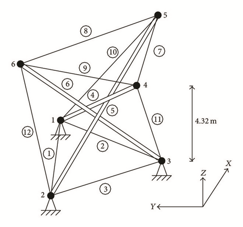
In the present work, the X-shape planar truss is formed by bars 5 and 6 and cables 3, 8, and 12, as shown in Figure 6. This stable planar structure is connected with bar 4 with the aid of cables 1, 2, 7, 9, 10, and 11, to create a stable three-dimensional structure. All elements are made of the same precious aluminum alloy. Linear elastic behavior is considered for loads below the yield stress. The technical characteristics of all members are shown in Table 8. Also, the weight of each joint is G = 0.01 kN. Cables 1, 2, 3, 10, 11, and 12 have a constant pretension equal to 0.01 kN/m along their length. The coordinates of all the 6 nodes of the structure are shown on Table 9. In applying the method, the set of equilibrium equations (8) is obtained which has 3N = 18 independent linear equations. There are Nb + Nur = 12 + 3 × 3 = 21 unknowns indicating a degree of redundancy equal to 3. However, since tensions in cables 1, 2, and 3 have no effect on the values of force densities of the other members, one has q1,2 = q1,3 = q2,3 = 0.01 kN/m. Then, the number of the unknowns is reduced to 18. Thus, the system of 18 linear equations is sufficient to give the solution to our problem. Matrix Ke of the linear system of equations has all the properties given by statements (1) to (4) of Section 3, verifying that our tensegrity structure is stable as expected.
| Type of member | Outer diameter do (mm) | Inner diameter di (mm) | Cross-sectional area A (mm2) | Moment of inertia I0 (m4) | Specific weight γ (kN/m3) | Young’s modulus E (GPa) | Yield stress σy (MPa) |
|---|---|---|---|---|---|---|---|
| Tension members (aluminium cables) | 20 | — | 314.16 | — | 31.85 | 89.17 | 260 |
| Compression elements 4 & 6 (aluminum rods) | 63.9 | 61.7 | 214.87 | 1.07 × 10⁻⁷ | 31.85 | 89.17 | 260 |
| Compression element 5 (aluminum rod) | 58.4 | 54.9 | 311.45 | 1.25 × 10⁻⁷ | 31.85 | 89.17 | 260 |
| Node i | xi (m) | yi (m) | zi (m) |
|---|---|---|---|
| 1 | 3.0 | −1.73205 | 0.0 |
| 2 | 0.0 | 3.46410 | 0.0 |
| 3 | −3.0 | −1.73205 | 0.0 |
| 4 | −4.618802 | 0.0 | 4.32049 |
| 5 | −0.479058 | −0.82975 | 4.32049 |
| 6 | 2.309401 | 4.0 | 4.32049 |
The values of the reaction forces on the supports and of all the forces and the corresponding force densities on the members of the structure are presented in Table 10. Also, it is verified that for this 3D problem the structure passes axial yield and Euler buckling criteria.
| Force density on a member | Value of qi,j with CEEMFD (kN/m) | Value of qi,j with DRM (kN/m) | Length Li,j of a member (m) | Value of Fi,j with CEEMFD (kN) | Value of Fi,j with DRM (kN) | Reaction force on a support | Value of reaction force with CEEMFD (kN) | Value of reaction force with DRM (kN) |
|---|---|---|---|---|---|---|---|---|
| q1,2 | 0.010000 | 0.010000 | 6.000000 | 0.060000 | 0.060000 | R1,x | 0.321956 | 0.322034 |
| q1,3 | 0.010000 | 0.010000 | 6.000000 | 0.060000 | 0.060000 | R2,x | −0.207729 | −0.207787 |
| q1,4 | −0.093977 | −0.093998 | 8.928200 | −0.839048 | −0.839231 | R3,x | 0.529678 | 0.529822 |
| q1,5 | 0.077393 | 0.077414 | 5.620020 | 0.434951 | 0.435068 | R1,y | −0.031957 | −0.031974 |
| q2,3 | 0.010000 | 0.010000 | 6.000000 | 0.060000 | 0.060000 | R2,y | 0.423712 | 0.423814 |
| q2,5 | −0.114623 | −0.114644 | 6.110100 | −0.700357 | −0.700484 | R3,y | 0.391755 | 0.391837 |
| q2,6 | 0.056172 | 0.056193 | 4.928199 | 0.276828 | 0.276931 | R1,z | 0.157097 | 0.157097 |
| q3,4 | 0.054744 | 0.054765 | 4.928199 | 0.269789 | 0.269892 | R2,z | 0.334522 | 0.334524 |
| q3,6 | −0.096973 | −0.096994 | 8.928200 | −0.865798 | −0.865984 | R3,z | 0.264438 | 0.264437 |
| q4,5 | 0.125318 | 0.125340 | 4.222079 | 0.529100 | 0.529194 | |||
| q4,6 | 0.013337 | 0.013342 | 8.000000 | 0.106699 | 0.106736 | |||
| q5,6 | 0.096702 | 0.096720 | 5.576919 | 0.539297 | 0.539401 |
4.5. A Two-Stage Self-Stressed 3D Tensegrity Structure
Zhang and Ohsaki [9] have also solved the problem of a two-stage self-stressed 3D tensegrity structure (Figure 7) by using the AFDM. In this example, the structure is considered to be weightless and is composed of 12 nodes and 30 members; that is, N = 12 and Nb = 30.
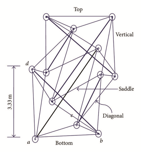
The structure contains 24 steel cables and 6 aluminum rods. The 24 cables are divided into four groups: (i) cables of the top and bottom bases, (ii) saddle cables, (iii) vertical cables, and (iv) diagonal cables, as indicated clearly in Figure 7. Its six rods are divided in two groups: (1) rods of the upper stage; (2) rods of the lower stage. Thus, in total, we have six groups of elements. Since the initial force densities and independent nodal coordinates can be arbitrarily specified, one can have some control over the geometrical and mechanical properties of the structure. Thus, the steel cables and the aluminum rods have equal stiffness (EA)r = (EA)c = 5426 kN. Also, the aluminum rods have a hollow cross section with a moment of inertia, about any diameter, equal to Ir = 2.894 × 10⁻⁹ m4. The only loading on the structure is the initial set of force densities q(o) applied in cables of all the six groups; that is, for the two groups of rods it is kN/m, for the saddle cables is kN/m, and for all the other cables is kN/m.
By specifying the coordinates of nodes a, b, and c, which are shown in Figure 7, to make the bottom base located on the xy-plane, and node d in the lower stage, we can have the configuration of the tensegrity structure as shown in Figure 7. The coordinates of these nodes are shown in Table 11. Then, the CEEMFD gives the set of final values of force densities, for the six groups of elements, which is listed in Table 12. These values are compared with those obtained with the AFDM, after 158 iterations [9]. The two sets of solutions compare favorably but in CEEMFD the solution is obtained directly. It is verified that the structure passes axial yield and Euler buckling criteria.
| Node i | xi (m) | yi (m) | zi (m) |
|---|---|---|---|
| a | −2.6667 | 0.0000 | 0.0000 |
| b | 1.3333 | −2.3094 | 0.0000 |
| c | 1.3334 | 2.3094 | 0.0000 |
| d | −1.8867 | 1.6666 | 3.3333 |
| Group → | Rods of the upper stage (1) | Rods of the lower stage (2) | Cables (top & bottom) (i) | Saddle cables (ii) | Vertical cables (iii) | Diagonal cables (iv) |
|---|---|---|---|---|---|---|
| Initial value (kN/m) | −1.5000 | −1.5000 | 1.0000 | 2.0000 | 1.0000 | 1.0000 |
| Final value (CEEMFD) | −1.8376 | −1.8376 | 0.9282 | 1.9920 | 1.1735 | 0.9957 |
| Final value (AFDM) [9] | −1.8376 | −1.8376 | 0.9281 | 1.9918 | 1.1737 | 0.9958 |
5. Conclusions
We have presented the CEEMFD to analyze 2D and 3D tensegrity structures. The resulting final linear system of equilibrium equations can be directly solved to give a unique solution for the force densities on the elements of the structure. For stable statically determinate structures, the global matrix Ke of the final system of equilibrium equations is square and has a nonzero determinant. For statically indeterminate structures, this matrix is not square. It is expanded to a square matrix after the implementation of Castigliano’s theorem which gives the additional equations required for the solution. The partial derivatives, which appear in the additional equations, are replaced by statically acceptable internal forces which are applied on the structure. For stable structures, the complete system of equations is then solved to give the values of the force densities on the members of the structure. Five problems of both planar and spatial tensegrity structures were solved. The results compare favorably with those obtained with the DRM and the AFDM [9] but the CEEMFD is faster as a direct method. As for future work we consider the extension of the method for geodesic domes and tensegrity bridges for pedestrians.
Competing Interests
The authors declare that there is no conflict of interests regarding the publication of this article.


