Guidance and Control Design for a Class of Spin-Stabilized Projectiles with a Two-Dimensional Trajectory Correction Fuze
Abstract
A guidance and control strategy for a class of 2D trajectory correction fuze with fixed canards is developed in this paper. Firstly, correction control mechanism is researched through studying the deviation motion, the key point of which is the dynamic equilibrium angle. Phase lag of swerve response is the dominating factor for correction control, and formula is deduced with the Mach number as argument. Secondly, impact point deviation prediction based on perturbation theory is proposed, and the numerical solution and application method are introduced. Finally, guidance and control strategy is developed, and simulations to validate the strategy are conducted.
1. Introduction
An important objective for future artillery projectiles is high delivery accuracy, in other words, improved aim to reduce round expenditure. In last few decades, several interesting concepts of guided projectiles were proposed, and they could be divided into three categories in terms of the control mechanisms employed: aerodynamic surfaces (nose-mounted canards, tail fins, and wedge-shaped paddle) [1–9], jet thrusters (gas or explosive thrusters) [10–13], and inertial loads (translating or rotating internal masses) [14, 15]. The first category of control mechanism presents some advantages over the other two: on one hand, the aerodynamic surfaces provide continuous time correction easier than jet thrusters; on the other hand, they potentially give the designer more control authority and bear more resemblance to missile trajectory control system. Furthermore, guided projectile concepts involving aerodynamic control devices can be divided into two categories: fin-stabilized (such as the US M712 Copperhead and the M982 Excalibur) and spin-stabilized (such as the US XM 1156 Precision Guidance Kit). Spin-stabilized guided projectiles are generally equipped with a roll-decoupled trajectory correction fuze, designed to provide range and lateral trajectory correction, while at the same time they rely on the high spin rate of the aft part for airframe stability. But the high spin rate creates an important coupling between the normal and lateral axes of the body, which makes the dynamic characteristic rather complex.
Swerve response of the spin-stabilized is a key point of the dynamic characteristic to be studied, when control input is added. Ollerenshaw and Costello gave the close-form formulas for the magnitude and phase angle of a projectile excited by a control force in terms of fundamental and pointed out that spin-stabilized projectiles respond out of phase to control-force inputs forward of the center of pressure [16]. Fresconi and Plostins studied various control mechanism strategies for spin-stability projectiles and gave the correction authority under different conditions [17]. But this paper just introduced the strategies, and the conclusion could not be used in engineering application directly.
The trajectory correction fuze incorporates all the necessary electromechanical devices for guidance, navigation, and control system of the airframe. Due to the limit of the volume of the fuze, all the electromechanical devices must have high integration degree, which requires the guidance algorithm to have small amount of calculation but high accuracy.
The five main types of guidance most considered in guided ammunition contexts are trajectory shaping, model predictive guidance, path following, impact point prediction control, and proportional navigation. When only small correction to a trajectory is possible, only the later four are applicable. In model predictive guidance a model of the projectile and the environment is used in each update instant to compute a sequence of control actions, given the current state [18–20]. The accuracy of the guidance is decided by the model of the projectile. If we want high accuracy, a complex model is needed, and the more state variables are acquired, the higher accuracy is got. The disadvantage of this method is that the amount of calculation is too large. In path following guidance, the current position of the projectile is compared with the nominal trajectory and a control is applied to bring the projectile to the nominal trajectory in some near future [5]. A drawback with path following is that it only uses the position to correct the trajectory but it neglects the velocity, which means that the projectile will fly through the nominal trajectory and further corrections are needed. Trajectory integration is one of the impact points prediction, which makes use of numerical calculation of the trajectory to get the impact point. The predictive accuracy depends on the trajectory model, and the higher accuracy of the model, the higher precision of the predictive. The disadvantage of this method is that for long range shoots of the spin-stability the trajectory is complex, which will cause a large amount of calculation [21, 22]. Proportional navigation is a useful guidance method. But to our best knowledge, only projectiles with jet thrusters as actuators have taken this method [12, 13], and if the method can be used for other two concepts is needed to be researched. Of course, some new methods are proposed for guidance [23, 24]. Perturbation based guidance for a generic 2D trajectory correction fuze is proposed by Robinson, which uses perturbation theory to predict state variables of the projectile [25]. The advantage is that the onboard computer can compute the control signal quickly by the parameters loaded prior to flight, but there is still a drawback that the guidance algorithm only takes drag force in consideration.
In this paper, guidance and control algorithm for a class of spin-stabilized projectile with trajectory correction fuze is proposed. Section 2 presents the trajectory model of this projectile. Section 3 studies the response of trajectory correction. Section 4 introduces a new impact point prediction methods and its application. Section 5 describes the process of guidance and control, and conclusion is provided in Section 6.
2. Trajectory Model
Trajectory correction fuze is attached to the projectile by screw thread, and by the bears in the fuze the guided projectile is divided into two parts: the front part called correction part and the aft part called body part. On the correction part, two sets of fixed canards are mounted; one has the same cant angle called steering canards to provide control force, and the other called rotation canards has the opposite cant angle to rotate the correction part by the rotational moment, as is shown in Figure 1.
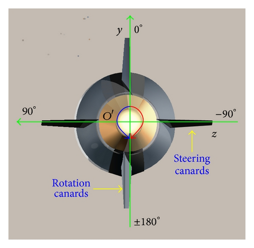
The definition for the roll angle of the correction part is also given in Figure 1. Define the roll angle to be 0 deg, when the steering canards are in horizontal plane and provide upward force, whereas when providing downward force, the roll angle is at the position of 180 deg. And the positive direction of the correction part is left, when looking from nose to the base.
2.1. Reference Coordinate System
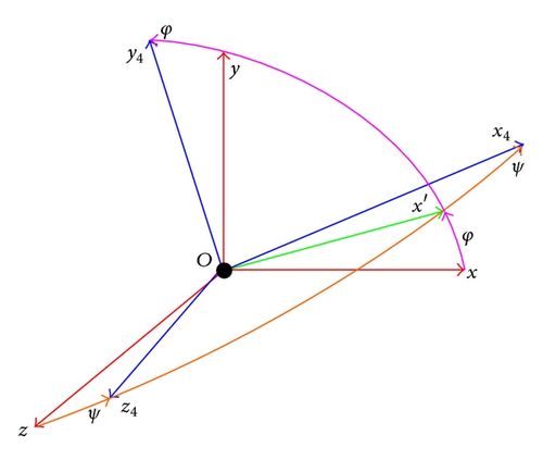
Two reference coordinate systems are needed in the present analysis: ground launch system and quasi body system. The ground launch frame is an approximation of the earth inertial reference frame. It is a fixed, nonrotating frame, and it neglects the earth’s curvature and rotation. Its x and z axes are in the horizontal plane and its y-axis is normal to the x-z plane, pointing upward. The original is set at the end of the gun tube, and the x-axis points ahead along the launching direction, while the z-axis points to the right when looking forward from the gun.
The quasi body reference frame Ox4y4z4 is fixed to the projectile with its original at the projectile center of mass. Its x4-axis aligns with the centerline of the projectile and points forward out of the nose, its positive z4-axis to the right, and its y4-axis upward. Note that x4-y4 plane is fixed in the vertical plane, and it is more convenient to describe the motion of the projectile. The sequence of rotation from the ground launch reference is pitch φ, yaw ψ, as is shown in Figure 2.
2.2. Trajectory Model
During the flight, the two parts of the projectile spin in different directions due to the effort of the aerodynamic forces. In order to describe the motion of the projectile, three translational and four rotational rigid body degrees of freedom are introduced. The translational degrees of freedom are the three components of the mass center position vector. The rotational degrees of freedom are the Euler yaw and pitch angles as well as the correction part roll and body part roll angles.
3. Control Mechanism Strategy
In this section, control mechanism strategy is researched. Firstly, formula for dynamic equilibrium angle caused by the trajectory correction is deduced based on the equations of the angle motion. Then, swerve response is studied by researching the deviation motion, and the formulas for the magnitude and the phase angle are acquired. Finally, formula for the phase angle of a spin-stability projectile with Mach number as argument is got.
3.1. Dynamic Equilibrium Angle Caused by Correction
When deducing the equation of angle motion, a few assumptions are invoked.
3.2. Swerve Response of Spin-Stability Projectiles
The point mass trajectory model is the first order approximation of the real trajectory, which only takes the gravity as well as the zero yaw axial force in consideration. In the flight, other aerodynamic forces and moments act on the projectile and make the flight contrail diverge from the point mass trajectory. The motion which is perpendicular to the point mass trajectory is called the deviation motion [26].
3.3. Phase Angle Analysis
The steering canards mounted on the fuze have fixed cant angle, and trajectory correction is realized by adjusting the roll angle of the correction part. So the key point of the control for this class of spin-stabilized projectile is the phase angle between command angle and the direction response.
Take a certain class of spin-stabilized projectile with fixed canards as example, as is shown in Figure 3. Muzzle velocity is 897 m-s−1, and the mass is 45.5 kg. A simulation experiment is conducted for the phase angle analysis.

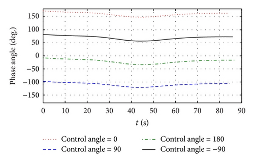
The projectile was fired at elevation 45 deg, and standard meteorological condition was taken. In simulation correction control began with 10 s, and the command angle was set at 0 deg, 90 deg, 180 deg, and −90 deg, respectively. The results gotten are shown in Figure 4. The four curves have the same changing trend.
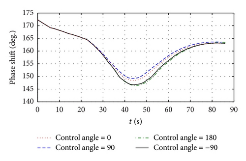
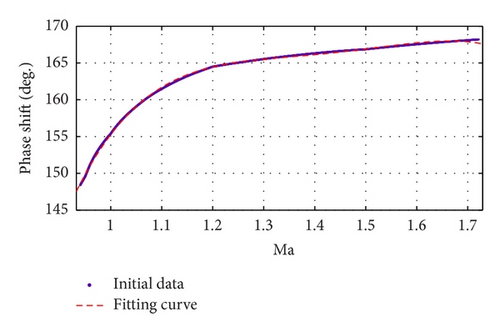
Define ϕd to be the phase shift, which is the angle between the command angle and the direction of the response, and the curves of ϕd are shown in Figure 5. The four curves have small difference, and when the time t is 42.6 s, the biggest magnitude difference is got, which is about 3 deg.
4. Impact Point Deviation Prediction Based on Perturbation Theory
In this section theory of impact point deviation prediction based on perturbation theory is presented firstly. Then the numerical method and application are introduced. At the same time, for projectiles using GPS receiver as the trajectory measurement tool, a second-order fading memory filter is designed. Finally, prediction accuracy is studied by simulation.
4.1. Impact Point Prediction Based on Perturbation Theory
X0(x0, y0, z0) and XT(xT, yT, zT) are the positions of the gun and target, respectively. Given the muzzle velocity, the trajectory impacting the target can be acquired definitely. For unguided projectiles the trajectory is the only one, because the range of elevation of the gun is restricted, and the trajectory is called nominal trajectory. Define XT = Φ(x, y, z, vx, vy, vz) to be function of nominal trajectory, with x as argument and vx, vy, vz, y, z as state variables.
- (1)
The impact point XIm should be close to the target XT, and the disturbance magnitudes should not be big ones.
- (2)
Predictive accuracy should meet requirements.
4.2. Numerical Method and Application
XT = Φ(x, y, z, vx, vy, vz) is an implicit function. Taking analytic method to study the predictive accuracy is very hard, while numerical method is a useful way. Numerical method is taken in this paper, and application of partial derivative, nominal trajectory is researched.
In order to predict the deviation in real time, the guidance system needs to acquire the information of velocity and position; at the same time it should get the partial derivatives and disturbance magnitudes. In application, partial derivatives and nominal trajectory are loaded on the onboard computer prior to flight. The information of velocity and position can be acquired by global position system (GPS) receiver, or inertial measurement unit (IMU). The projectile mentioned above takes GPS receiver.
The unguided trajectory whose elevation is 45 deg is used as nominal trajectory, and the trajectory whose elevation is in the neighborhood of 45 deg is used as the disturbance trajectory. The advantage is that the impact point deviation is the same value along the trajectory.
4.2.1. Numerical Computing of Partial Derivatives
Here velocity step and position step are defined, which are velocity and position disturbance. In this part, how to select the velocity step, position step, and order of the Taylor expansion is presented. Select the trajectory whose elevation is 45.5 deg as disturbance trajectory.
The predictive results of downrange deviation using first and second-order partial derivatives are shown in Figure 7, when velocity step and position step are 2 m-s−1 and 5 m, and rows of partial derivatives and nominal trajectory are 20 and 75, respectively. Compared with result of first order, result of second-order has big amplitude, and the convergence is slow. So first order partial derivatives is preferred.
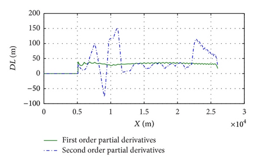
Figure 8 shows the predictive results with different velocity steps and position steps, when rows of partial derivatives and nominal trajectory are 20 and 75, respectively. When position step is 5 m, results are almost the same. But when velocity step is given as 2 m-s−1, results have big difference after range reaches 22 km. That is because the impact point is far away from the target, since magnitude of position step is too big. Here we select that velocity step and position step are 2 m-s−1 and 5 m.
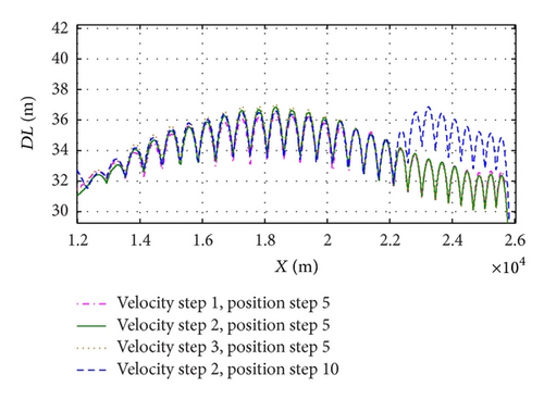
Table 1 shows twenty rows of partial derivatives of nominal trajectory, and values of each line are almost liner. Simulation results show that selecting 20 rows is suitable, since adding rows will not improve the accuracy of prediction.
| Range | ∂Φx/∂vx | ∂Φx/∂vy | ∂Φx/∂vz | ∂Φx/∂y | ∂Φx/∂z | ∂Φz/∂vx | ∂Φz/∂vy | ∂Φz/∂vz | ∂Φz/∂y | ∂Φz/∂z |
|---|---|---|---|---|---|---|---|---|---|---|
| 5146.29 | 26.41 | 26.48 | −4.4 | 1.18 | −0.0013 | −0.31 | 1.25 | 47.98 | 0.069 | 0.99658 |
| 6707.75 | 27.53 | 25.95 | −4.45 | 1.04 | −0.0017 | −0.57 | 1.26 | 48.6 | 0.0689 | 0.99688 |
| 8144.93 | 27.8 | 25.87 | −4.06 | 0.86 | −0.0021 | −0.84 | 1.26 | 48.38 | 0.062 | 0.99718 |
| 9487 | 27.7 | 25.74 | −3.59 | 0.71 | −0.0024 | −1.05 | 1.22 | 47.5 | 0.055 | 0.99747 |
| 10753.4 | 28.7 | 26.12 | −3.33 | 0.66 | −0.0028 | −1.09 | 1.13 | 46.2 | 0.055 | 0.99775 |
| 11962.3 | 30.35 | 26.06 | −2.99 | 0.62 | −0.003 | −0.91 | 1.01 | 44.2 | 0.056 | 0.99801 |
| 13128.3 | 31.0 | 24.94 | −2.96 | 0.604 | −0.0035 | −0.71 | 0.86 | 41.7 | 0.0564 | 0.99825 |
| 14260.2 | 30.7 | 23.19 | −2.19 | 0.58 | −0.0039 | −0.46 | 0.75 | 39.2 | 0.057 | 0.99848 |
| 15363.2 | 29.74 | 21.79 | −1.6 | 0.57 | −0.0042 | −0.15 | 0.73 | 36.4 | 0.0565 | 0.99870 |
| 16440.2 | 28.25 | 20.2 | −1.4 | 0.55 | −0.0045 | −0.62 | 0.81 | 33.4 | 0.053 | 0.99892 |
| 17492.6 | 26.19 | 18.31 | −0.87 | 0.54 | −0.0048 | −1.03 | 0.88 | 30.5 | 0.0503 | 0.99913 |
| 18519.1 | 23.73 | 16.57 | −0.29 | 0.53 | −0.005 | −1.01 | 0.93 | 27.5 | 0.0495 | 0.99930 |
| 19518.4 | 21.6 | 14.4 | −0.33 | 0.52 | −0.005 | −0.82 | 0.84 | 24.5 | 0.0495 | 0.99944 |
| 20487.7 | 19.5 | 12.42 | −0.16 | 0.51 | −0.0058 | −0.66 | 0.76 | 21.5 | 0.049 | 0.999574 |
| 21422.9 | 17.04 | 10.39 | −0.07 | 0.5 | −0.006 | −0.54 | 0.66 | 18.6 | 0.0486 | 0.99968 |
| 22319.2 | 14.62 | 8.83 | −0.15 | 0.49 | −0.006 | −0.42 | 0.59 | 15.6 | 0.0479 | 0.999768 |
| 23171.8 | 12.0 | 6.82 | 0.028 | 0.48 | −0.006 | −0.33 | 0.45 | 12.7 | 0.0471 | 0.999838 |
| 23975.6 | 9.27 | 4.92 | −0.05 | 0.47 | −0.007 | −0.24 | 0.32 | 9.64 | 0.0463 | 0.999891 |
| 24726.5 | 6.32 | 3.42 | 0.17 | 0.46 | −0.007 | −0.16 | 0.23 | 6.51 | 0.0455 | 0.999926 |
| 25421.5 | 3.03 | 1.43 | −0.004 | 0.46 | −0.007 | −0.08 | 0.086 | 3.13 | 0.0449 | 0.999943 |
4.2.2. Numerical Computing of nominal Trajectory
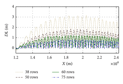
Nominal trajectory loaded on the onboard computer is discrete values with range x as argument. In application standard value of state variables is acquired by interpolation to the nominal trajectory, and the error between standard value and real value will cause predictive error. Adding rows of nominal trajectory to reduce the range interval is an effective way to improve the predictive accuracy.
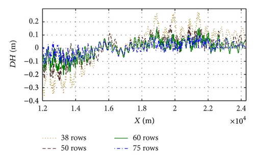
Figure 9 shows the results of prediction with different rows of nominal trajectory, when using nominal trajectory as disturbance trajectory. The downrange predictive results change as half sinusoid, and the period is just the sampling period, which means that at the sampling point the predictive error is 0. The bigger the sampling period is, the bigger the predictive error is. When the rows reach 75, the downrange error is less than 0.8 m, and the lateral error is less than 0.1 m, whereas, it just occupies no more than 5 k of RAM.
4.3. Fading Memory Filter
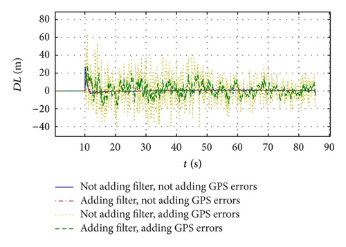
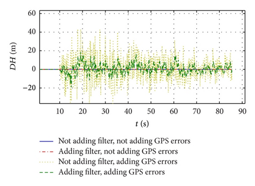
The filter results of the predictive deviation are shown in Figure 10, and the results meet the requirements.
4.4. Prediction Accuracy
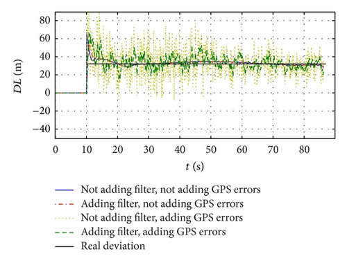
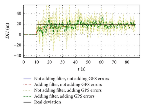
As is mentioned above, the unguided trajectory whose elevation is 45 deg is used as nominal trajectory, and the trajectory whose elevation is in the neighborhood of 45 deg is used as the disturbance trajectory. Here trajectory with elevation being 45.5 deg is the disturbance trajectory, and its impact point deviation is a constant, as is shown in Figure 11. Downrange predictive result reflects the real deviation before adding GPS errors, and the predictive error is not more than 2 m. After adding GPS errors, the downrange predictive results also can meet the accuracy requirement. For lateral prediction, till 40 s the convergence of prediction is got, and the results are aligned with the lateral deviation. Figure 11 presents that the lateral prediction results can describe the deviation; just the errors are a little big, but still not more than 15 m.
Impact point deviation prediction based on perturbation theory for spin-stabilized projectiles has high prediction accuracy and has small calculation amounts. It is suitable for application on the trajectory correction fuze.
5. Process of Guidance and Control
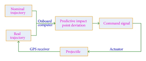
For the spin-stabilized projectile mentioned above, the onboard GPS receiver gets the velocity and position information of the real trajectory every 0.1 s and then onboard computer samples the information, predicts impact point deviation, generates command signal, and controls the actuator to make the correction part steady at a setting angle to correct the real trajectory, which is also a disturbance trajectory, as is shown in Figure 12. The key points are the command signal generation and strategy of guidance and control.
5.1. Command Signal Generation
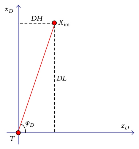
The objective of correction control is changing the state variables to make the predictive derivation 0 to realize impacting the target precisely, by adjusting the roll angle of steering canards mounted on the correction part. As correction control mechanism is studied in Section 3, the pivotal problem to be researched is the relationship between changes of state variables and impact point derivation.
5.2. Control Strategy
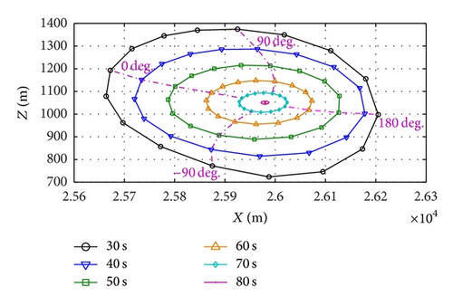
As expected, Figure 14 indicates that control authority decreases with the control instant delay, from when the correction part is set at the given roll angle till the projectile impacts the ground. If correction control begins with 30 s, the largest downrange correction authority from far to target is about 260 m, and from near to target is about 300 m, whereas the lateral correction authority is about 260 m.
As is mentioned in Section 5, the predictive derivations have high accuracy after 40 s, and the lateral derivation has predictive errors before 40 s, but it can still reflect the sign of the lateral derivation, which means that from the predictive derivation we can know the predictive impact point is on left or right of the target. Here the control strategy is divided into two segments: in ascending segment only lateral correction is invoked, while comprehensive correction is conducted in descending segment. The command signals in the two segments are shown as follows:
5.3. Simulation Results
5.3.1. Simulation of the Control Trajectory
In order to validate the effectiveness of the control strategy simulation of control trajectory was conducted with the elevation being 44 deg. From Figures 15 and 16, the control trajectory approaches nominal trajectory constantly and impacts the target. Figure 16 indicates that in the lateral plane the control trajectory traverses the nominal trajectory twice. Figures 15 and 16 validate the effectiveness of the control strategy.
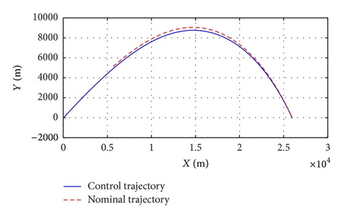
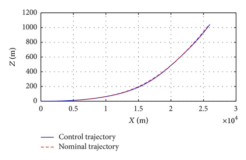
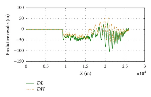
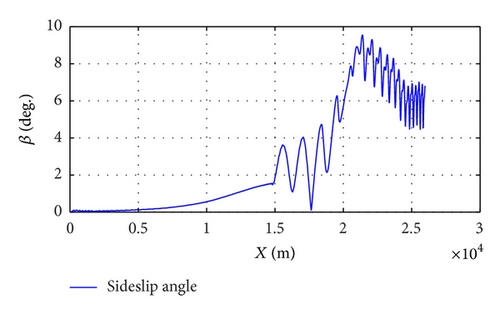
Figure 17 presents the result of predictive impact point deviation, and it shows that the two curves are close in upon the target in general trend. There is no gyroscope installed on the guidance and control system, so there is no angular feedback. The control force makes the sideslip angle dither, as is shown in Figure 18, and the control trajectory shows a small wobble, which is reflected in Figure 17. The magnitude of sideslip angle is about 10 deg, but after that it declines, which indicates in flight the projectile is kept in stable condition.
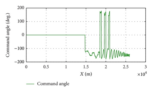
When an unguided projectile mentioned above is fired, range and cross range are all smaller than the two of nominal trajectory, and the downrange deviation takes the dominating part. So the phase angle of swerve response needs to be set in the neighborhood of 0 deg to correct the trajectory. Since phase lag exits, command angle should be set at the position ahead the phase angle of swerve response, as is shown in Figure 19.
5.3.2. Results of Monte Carlo Targeting
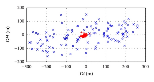
Adding all kinds of disturbances, as is shown in Table 2, such as winds, muzzle velocity perturbation, and errors of launching elevation angle, miss distances without guidance and control are shown in Figure 20, which indicates that downrange miss distance is bigger than the lateral one. When guidance and control are taken, the miss distance is much smaller, and CEP is not more than 30 m. Simulation results show that control strategy based on impact point derivation prediction proposed in this paper is suitable for trajectory correction of this class of spin-stabilized projectile.
| Parameter | Unit | Deviation value |
|---|---|---|
| Mass | kg | ±0.5 |
| Length | mm | ±5 |
| Moment of inertia | % | ±4 |
| Muzzle velocity | m/s | ±5 |
| Launching elevation angle | deg | ±0.06 |
| Launching azimuth angle | deg | ±0.02 |
| Wind velocity | m/s | ±2 |
| Wind direction | deg | ±15 |
6. Conclusions
Guidance and control strategy for a class of spin-stabilized projectile with 2D trajectory correction fuze is presented in this paper. Based on correction control mechanism study, control strategy using impact point derivation prediction based on perturbation theory is proposed. Simulation results show that the strategy designed is suitable for this class of projectiles, and the miss distance is reduced effectively.
Conflict of Interests
The authors declare that there is no conflict of interests regarding the publication of this paper.


