Epoxy Resin Composite Bilayers with Triple-Shape Memory Effect
Abstract
Triple-shape memory epoxy composites with bilayer structures of well-separated glass transition temperatures have been successfully prepared. The different glass transition temperatures of the epoxy composites were obtained by physically incorporating various amounts of nanosilica particles, which were introduced into the epoxy by utilizing polyethylene glycol. A scanning electron microscope and a transmission electron microscope were used to analyze the dispersibility of the nanosilica particles. The effects of nanosilica particles on the mechanical properties as well as on the dual-shape memory effects (DSME) and triple-shape memory effects (TSME) of the nanocomposites were studied. The nanosilica particles were homogenously dispersed in the matrix and well incorporated into the epoxy matrix. The resulting nanocomposites exhibited excellent TSME, and their shape fixity properties were significantly improved by nanosilica particles.
1. Introduction
Shape memory polymers (SMPs) are smart materials that can fix their deformed temporary shapes and recover their permanent shapes in a defined way upon external stimuli [1–3]. SMPs have attracted considerable attention because of their promising applications in textiles [4–6], adhesives [4, 5], smart coatings [4–9], biomedical devices [4–6, 10], and aerospace structures [6, 10].
In recent years, triple-SMPs (TSMPs) have received even greater attention because shape changes are no longer limited to being unidirectional but could now potentially offer unique opportunities in many applications, including morphing aircrafts, fasteners, and medical devices [1, 11]. Unlike conventional dual-SMPs, which can recover from a temporary shape to a permanent shape, TSMPs can fix two temporary shapes and recover sequentially from one temporary shape to the other and eventually to the permanent shape [12]. TSMPs have either more than one switching thermal transition [1] or a single switching transition with a broad thermal transition range [13]. Triple-shape memory effects (TSME) can be achieved through many ways, including polymers blends, grafting and blocking copolymers, SMP hybrids, and polymer laminates [14]. Bellin et al. [15] first reported a SMP with a two-step TSME by copolymerizing poly(ethylene glycol) monomethyl ether monomethacrylate with poly(caprolactone) dimethacrylate. The grafting and blocking copolymers of different soft segments result in more than one well-separated multiple phase in a single SMP. Bae et al. prepared SMPU bilayer films of different molecular weights with nanosilica particles acting as multifunctional cross-links and reinforcing fillers [16]. Xie et al. prepared TSMP bilayer epoxy by curing the high Tg epoxy layer on top of the low Tg epoxy layer [1].
Herein, novel triple-shape memory epoxy nanocomposites with two different glass transition temperatures have been prepared through casting nanosilica/epoxy nanocomposites layer by layer. By varying the amounts of polyethylene glycol (PEG) and nanosilica in the epoxy system, we achieved a series of composite layers with different glass transition temperatures. The dispersibility of the nanosilica particles was evaluated via field emission scanning electron microscopy (FE-SEM) and transmission electron microscopy (TEM). The effects of the nanosilica particles on the mechanical and shape memory properties of the composites were analyzed and discussed.
2. Experiment
2.1. Materials
Epoxy resin E-51 (WSR618) and the curing agent (PA) were procured from Jinhong Resin Factory, Hangzhou, China. Nanosilica (15 ± 5 nm) was obtained from Aladdin Chemical Reagents Co., Ltd., Shanghai, China. Polyethylene glycol 200 (PEG200) was purchased from Shanghai Putong Gaonan Chemical Plants, China.
2.2. Preparation of SiO2/Epoxy Resin Nanocomposites
SiO2/epoxy nanocomposites were prepared according to our previous report with a slight modification [17]. Typical procedure was as follows: a known amount of SiO2 was dispersed in PEG by mechanical stirring for 3 h. Then epoxy resin and curing agent were dissolved in the SiO2 dispersion under mechanical stirring for another 0.5 h. Subsequently, the mixture solution was degassed placed in a vacuum oven. And then, the mixture solution was poured into a Teflon mold, cured at 60°C for 4 h. Changing the mass ratio of the SiO2 and PEG in the mixture and according to the above method, the SiO2/epoxy nanocomposites were obtained with different mass ratio of 1 wt% and 2 wt%, respectively. Meanwhile, the pure epoxy and the PEG mixed epoxy composites were also prepared in the absence of nanosilica particles via the method described above. The stoichiometric amounts of every material used to prepare the SiO2/epoxy nanocomposites have been listed in Table 1.
| E-51 (g) | PA (g) | Nanosilica (g) | PEG (g) | |
|---|---|---|---|---|
| EP | 50 | 39 | 0 | 0 |
| A10 | 50 | 39 | 0 | 20 |
| A00 | 50 | 39 | 0 | 10 |
| A01 | 50 | 39 | 1 | 10 |
| A02 | 50 | 39 | 2 | 10 |
Bilayer SiO2/epoxy nanocomposite was prepared as follows: the mixture solution A02 was poured into a Teflon mold, cured at 60°C for 0.5 h. And then the mixture solution A10 was poured on top of the A02, cured at 60°C for 3.5 h. Finally, the bilayer SiO2/epoxy nanocomposite was obtained with the weight ratio of A02 to A10, that is, 2 : 1, and the sample was designated as B21.
2.3. Characterization
The dispersibility of nanosilica particles dispersed in PEG and the fracture surfaces of some samples were characterized by field emission scanning electron microscope (ZEISS ULTRA55) and transmission electron microscope (TEM, JSM-2100).
Tensile properties of the composites were measured by using a universal testing machine (UTM) (Instron 3367R4415, Canton, MA, USA) at a crosshead of 5 mm/min. The dimensions of the rectangular film were 50 mm × 5 mm × 2 mm, and the length gripped the sample was 30 mm.
Dynamic mechanical analysis (DMA) was performed with the use of DMA Q800 (TA Instruments, New Castle, USA) in a uniaxial tension mode at 1 Hz and a heating rate of 3°C/min. The dimensions of the rectangular film were 10 mm × 5 mm × 2 mm.
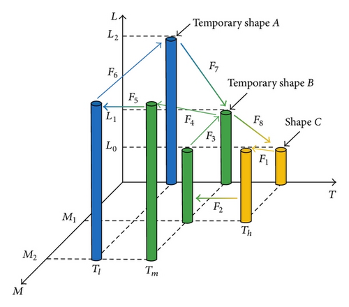
Tl, Tm, and Th are set to 15°C, 42°C, and 72°C, respectively; εmB = 2.5% and εmA = 5%.
3. Results and Discussion
3.1. Morphology of Nanocomposites
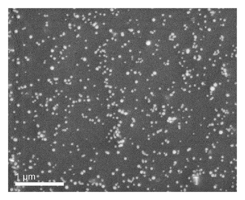
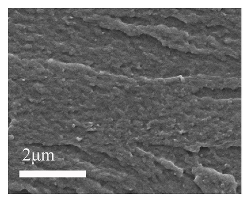
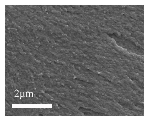
Figure 2 shows the morphology evolution of nanosilica dispersed in PEG. Figure 2(a) and Figure 2(b) are the TEM and FE-SEM images of nanosilica dispersed in PEG, respectively. It confirms that the nanosilica particles are well distributed and no agglomerates present in the PEG. The cryofractured cross section of the silica/epoxy nanocomposites was observed by FE-SEM. In Figure 3, the samples A01 (Figure 3(a)) and A02 (Figure 3(b)) images reveal that the nanosilica particles are also well dispersed in the epoxy matrix. Through the typical process, it is noted that the obtained silica/epoxy nanocomposites are fully composed of well dispersion of nanosilica particles within epoxy matrix, which may lead to excellent mechanical properties of composites [17].

3.2. Dynamic Mechanical Properties
The dynamic mechanical properties of samples from the DMA test are shown in Figure 4. The samples A10, A00, A01, and A02 prepared in this study possess glass transition temperatures (Tgs) of 36°C, 38°C, 48°C, and 65°C, respectively, based on their tan delta peaks in the DMA curves (as shown in Figure 4(a)), as shown in Table 2. It is also noted that the Tg of sample was increased with the increasing amount of nanosilica and decreased with the increasing amount of PEG, which was attributed to the segmental motion of polymer that was hindered by nanosilica particles and PEG acted as a plasticizer.
| Sample | A10 | A00 | A01 | A02 | B21 |
|---|---|---|---|---|---|
| Tg (°C) | 36 | 38 | 48 | 65 | 30, 66 |
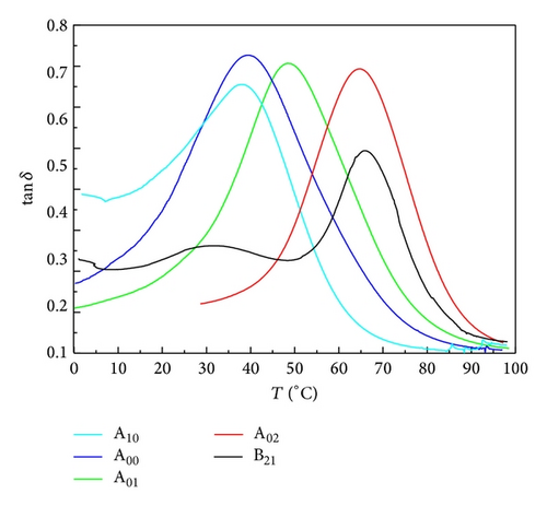
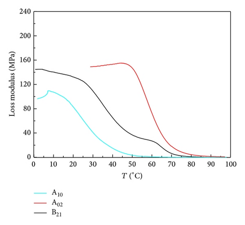
In view of the well phase mixing of nanocomposites, A02 and A01 show a relatively narrow switching transition, implying that sufficient chain movement is achieved within that short temperature regime. The tan δ peaks of all of samples are relatively high (higher than 0.6) indicating that the significant difference between viscous and elastic components of SMP in the Ttrans regime, which is of great benefit to shape recovery ratio of sample [20–22]. Moreover, in Figure 4(a), two tan δ peaks can be clearly observed in the curve of B21, and it is also found that the sample B21 possessed the two well-separated glass transitions, which is shown in Figure 4(b). This phenomenon could be attributed to the formation of the phase-separated bilayer structure and provided the conditions to achieve TSME.
3.3. Mechanical Properties of the Composites
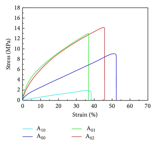
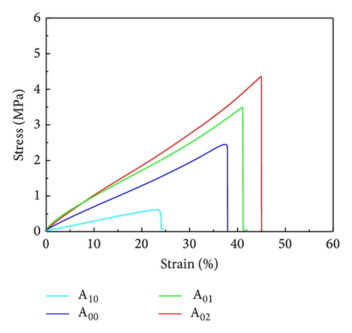
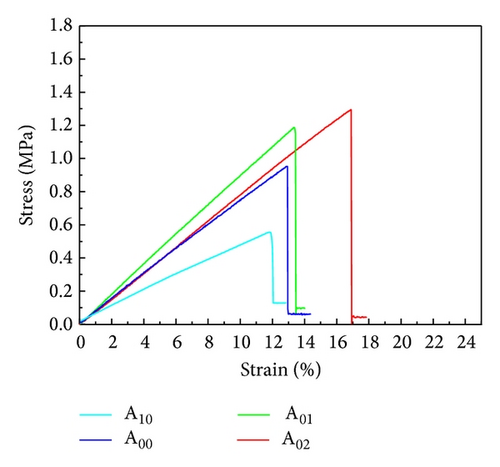
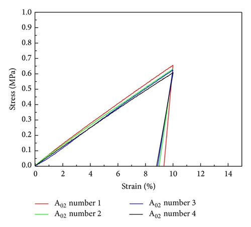
Figure 5 shows the stress-strain behaviors of the composites at different temperatures. It can be seen from the results of Figures 5(a), 5(c), and 5(e) that the break strength and elongation of the silica/epoxy nanocomposites were improved by the addition of nanosilica particles, except for the sample A00 that has better break elongation than the samples A01 and A02 at 15°C. It may be attributed to the reinforcing function and homogenous dispersion of the nanosilica particles as observed in the FE-SEM images (Figure 3). Moreover, the samples A01 and A02 also show good strain energy storage capacity which can be obtained from the area under the stress-strain curve, implying that the silica/epoxy nanocomposites may have better shape recovery effect [16, 20]. Meanwhile, the break strength and the elongation of the composites decreased with the increasing amount of PEG, indicating that PEG serves as plasticizer.
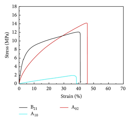
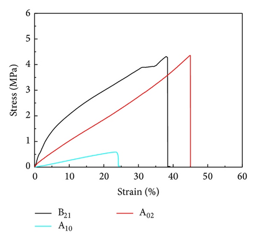
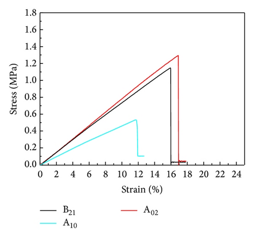
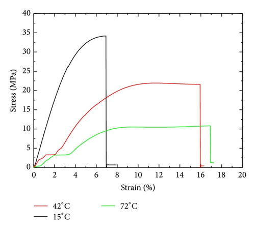
The stress-strain behaviors of B21 depend on the temperature as illustrated in Figures 5(b), 5(d), and 5(f). Comparing with the stress-strain behaviors of B21 at 15°C and 72°C, B21 at 42°C exhibits an interesting phenomenon of the stress maintaining almost constant when the strain increased from 31% to 34%. This is mainly because the sample B21 is consisted of two layers, including A10 layer in the rubbery state and A02 layer in the glassy state at 42°C, respectively. Additionally, A10 layer of B21 does not break at the strain of approximately 25%, whereas the sample A10 breaks. This result might be due to the powerful interfacial adhesion of the two layers. For comparison, stress-strain behavior for pure EP at different temperatures is displayed in Figure 6. A notable difference between EP composites and pure EP is that the failure strain of EP composites is greatly improved due to the addition of PEG in EP matrix.
3.4. Shape Memory Behavior
3.4.1. DSME
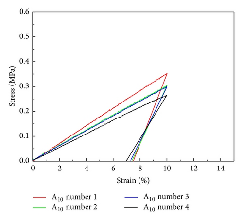
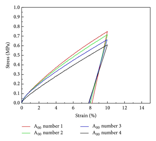
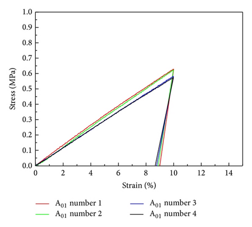
The four cycles of thermomechanical behavior of the composites are shown in Figure 7, and the detailed data are summarized in Table 3. On the basis of DMA curves (Figure 6(a)), the rubbery state and glassy state of the samples A02 and A01 can be achieved at 72°C and 42°C, and those of the samples A00 and A10 can be achieved at 42°C and 20°C, respectively. The composites deformed in their rubbery state and generated a decrease in conformational entropy of the constituent polymer network chains. Then, the cooling down of the deformed material triggered vitrification, which kinetically traps the SMP in its low entropy state as a result of a significant reduction in chain mobility. Shape recovery is later initiated by reheating the material under stress-free conditions and allowing for the relaxation of polymer chain segments (with regained mobility) to their original entropically favored conformational state [11]. Additionally, it should be noted that the shape fixities of A00 and A10 are relatively low while the samples A01 and A02 display better shape fixities at 87–93% for the four cycles, which may be contributed from the addition of nanosilica particles. Furthermore, The shape recovery effect of all the samples was 96%–99%, especially the sample A02 that is better than the others. This finding is coincident with previous analysis.
| N(a) | Fixity ratio (%) | Shape recovery ratio (%) | ||||||
|---|---|---|---|---|---|---|---|---|
| A10 | A00 | A01 | A02 | A10 | A00 | A01 | A02 | |
| 1 | 75 | 82 | 90 | 93 | 98 | 99 | 99 | 99 |
| 2 | 74 | 80 | 89 | 90 | 98 | 99 | 99 | 99 |
| 3 | 73 | 79 | 88 | 89 | 98 | 98 | 98 | 99 |
| 4 | 70 | 78 | 87 | 88 | 96 | 97 | 97 | 97 |
- (a)Thermomechanical cycle number.
3.4.2. TSME
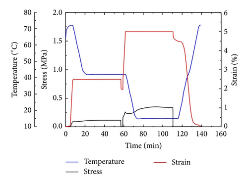
The triple-shape memory capability for B21 is shown in Figure 8. The sample was first strained to 2.5% at 72°C, which was followed by cooling down to 42°C. After the stress was released, the strain instantaneously shrunk to 1.96%. At this step, the shape fixity was decided by the molecular frozen of A02 because rubbery state of A10 tended to recoil the sample. At last, the shape fixity ratio RfB of 78% was achieved. Then, the sample was stretched to 5% at 42°C, followed by cooling down to 15°C and the subsequent releasing of the stress, and the strain shrunk from 5% to 4.5%. At 15°C, although both A02 and A10 were in glassy state, A02 had a tendency to keep shape B, resulting in RfA of 84%. Finally, the sample was reheated to 42°C and 72°C; the strain was 2% and 0.04% at 42°C and at 72°C, respectively. RrB = 97% and RrC = 100% were calculated based on (4).
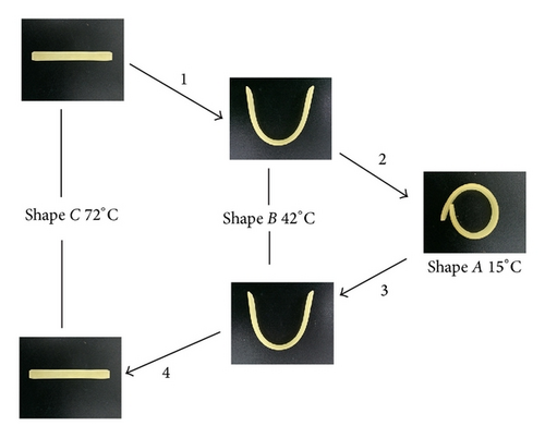
The TSME is further demonstrated visually in Figure 9. B21 was cut into a rectangular film of dimensions 50 mm × 5 mm × 2 mm (shape C). Shape C was first heated in an oven at 72°C and then quickly deformed to a “U” shape and quenched in a water bath at 42°C; some minor recovery occurred due to the not so perfect shape fixing ratio, but most of the deformation was kept and fixed at a temporary shape B (progress 1). After this, shape B was transformed into shape A and immersed in a water bath of 15°C; shape A was fixed at the same time (progress 2). Reheating to 42°C and 72°C, shape B and shape C recovered in turn (progress 3 and 4). Shape B and shape C behaved just the corresponding shape at the right temperature due to their excellent shape recovery ratio.
4. Conclusions
A novel bilayer epoxy system shape memory composites with TSME have been successfully synthesized and designed. The triple-shape memory nanocomposites were prepared by casting together two different shape memory composites exhibiting outstanding shape recovery effect. By varying the amount of PEG and nanosilica particles, we prepared a series of nanocomposites layers with different Tg. The dispersibility of the nanosilica particles and the failure strains of the nanocomposites were significantly improved by the addition of PEG. The mechanical and shape memory fixity properties of the composites were significantly improved by the addition of nanosilica particles.
Conflict of Interests
The authors declare that they do not have any commercial or associative interest that represents a conflict of interests in connection with the work submitted.
Acknowledgment
This work was supported by the National Natural Science Foundation of China (NSFC) (Grant no. 51473147).


