Low-Thrust Transfer Design of Low-Observable Geostationary Earth Orbit Satellite
Abstract
With radar and surface-to-air missiles posing an increasing threat to on-orbit spacecraft, low-observable satellites play an important role in low-thrust transfers. This paper presents the design for a low-thrust geostationary earth orbit (GEO) transfer control strategy which takes into consideration the low-observable constraint and discusses Earth shadow and perturbation. A control parameter optimization addresses the orbit transfer problem, and five thrust modes are used. Simulation results show that the method outlined in this paper is simple and feasible and results in reduced transfer time with a small amount of calculation. The method therefore offers a useful reference for low-thrust GEO transfer design.
1. Introduction
Creation of a low-observable satellite is accomplished by low-observable technology, which makes it difficult or impossible to avoid detection of satellites in orbit by hostile enemy forces [1–6]. Adding a low-observability module to the spacecraft’s overall design is key to improving operational effectiveness and satellite survivability.
A geostationary satellite is usually launched from ground to Low Earth Orbit (LEO) or Middle Earth Orbit (MEO) rather than to GEO. Since the main threat to LEO and MEO satellites comes from radar, a great deal of emphasis in low-observability design is placed on radar analysis. The radar cross section (RCS) is the designers’ only controllable factor in radar detection. Contemporary work on low observability has its roots in efforts at reducing the RCS of a spacecraft, falling into two categories: low-observable shape design and flight attitude planning [1–8]. The former is a simple way of reducing the range at which radar can detect the spacecraft; however, contouring the surface of a spacecraft to reduce the RCS equally in all directions is not possible. As a result, the latter is typically supplemented in designs in order to produce better results.
The application of electric propulsion in geostationary orbit platforms is inevitable for the development of the aerospace. Used for spacecraft applications in Earth orbit, such as station-keeping, orbit-raising, and orbit transfer, Boeing-702sp is an all-electric propulsion satellite with a specific impulse of more than 3800 seconds [9–12]. A great deal of research has been directed toward solving the low-thrust transfer problem. Most of that research has been based on optimal control theory. The numerical solution incorporates both direct and indirect methods, due to their high accuracy [13–16]. As is typical with these methods, the solution is often difficult to derive, requiring a complex initial guess and tedious iteration for convergence.
Electric propulsion, low thrust, and highly specific impulses have led to greatly improved fuel efficiency at the expense of relatively long transfer times. For these reasons, satellites can be easily caught by detection systems during low-thrust GEO transfer. Existing research on low-thrust transfer emphasizes optimum techniques, giving little consideration to the satellite attitude constraint of control. This paper models an optimization scheme of the low-thrust transfer based on low-observable technology, which can reduce the visibility of satellites. Furthermore, the optimization includes space environment (Earth shadow and perturbation). Offering the advantages of short time, a small amount of calculation, and no complex initial guess, the method designed in this paper can provide a valuable reference for low-thrust GEO transfer design.
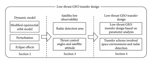
The paper is organized in five distinct sections, as represented in Figure 1. The introduction above has described low-observable satellites and low-thrust transfer optimization techniques. In Section 2, Earth shadow and perturbation in orbit transfer are analyzed. In Section 3, a mathematical model of low-observable constraint is demonstrated, including the radar detection area and the relationship of thrust control angle and attitude angle. Section 4 presents a method based on control parameter analysis to solve minimum-time transfer. Finally, we summarize the paper.
2. Dynamic Model
2.1. Modified Equinoctial Orbit Model
2.2. Eclipse Effects
To model the electric propulsion system accurately, it is necessary to model the satellite’s trajectory as it passes through the shadow of Earth. In particular, the satellite is at discharge, which leads to high power consumption when in the shadow. In order to ensure the safety of spacecraft, therefore, the thrust is 0 when the vehicle is in the shadow of Earth. A simplified Earth-shadow model, namely, the cylindrical projection model shown in Figure 3, is used to estimate the location of the shadow [17–20].
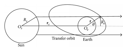
Referring to the geometry illustrated in Figure 3, rs is defined as the vector from Earth to the Sun, with norm ‖rs‖, and r as the vector from Earth to the satellite, with norm ‖r‖. Re is the radius of Earth, and Rs is the radius of the Sun.
2.3. Perturbation
Earth’s oblateness, atmospheric drag, light pressure, secondary body, and other factors in space can also perturb a satellite’s motion. Among these variables, Earth’s oblateness is of vital importance for predicting the trajectory of the satellite accurately. The oblate Earth perturbation is caused by the reality of Earth’s shape not being perfectly spherical. The impact of Earth’s oblateness due to J2 is always taken into account in the engineering calculations [20, 21].
3. Satellite Low Observability
The research activity presented here is focused on the optimum algorithm and does not take into account space environment analysis, especially the low-observable constraint. The low-observable satellite is designed to minimize its frontal RCS, requiring low-observable shape design and flight attitude adjustment [6–8]. The satellite keeps its front toward Earth when it is flying over ground-based radar detection areas.
3.1. Radar Detection Area
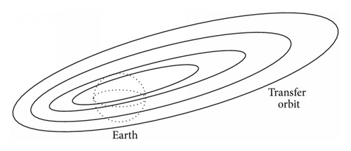
In order to avoid reflecting radar signals directly, the scanning range of the ground-based radar should be modeled first. Figure 4 shows low-thrust GEO satellite transfer with no radar detection. Figure 5 is an illustration of that GEO satellite being detected in low-thrust transfer by a ground-based radar, and the shadow is the radar detection area.
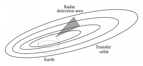
Due to the limited energy and probability of intercept, radar repeats its search for the target in a narrow area, which is modeled as a specific coverage of yaw angle, pitch angle, and operating distance, rather than the entire airspace [22–24].
The latitude and longitude of the ground station are defined, respectively, as λp and δp. S is the track of the subsatellite point, whose right ascension and declination are denoted as λ and δ. We is the rotation speed of Earth.
3.2. Thrust Control Angels and Satellite Attitude
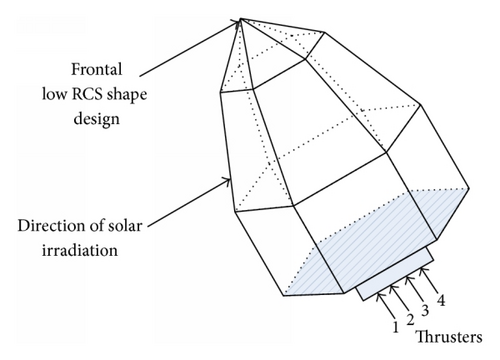
4. Low-Thrust GEO Transfer Design
The goal of this paper is to design a minimum-time transfer for geostationary spacecraft equipped with electric propulsion systems. The transfer problem is thus to find an essentially bound control to reduce eccentricity and inclination and raise the semimajor axis.
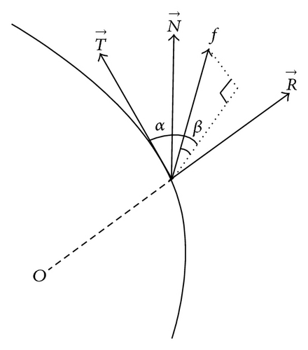
The acceleration component fn only contributes to a decrease of inclination. The change of the semimajor axis and eccentricity are both related to fr and ft. fr and ft have a greater effect on the semimajor axis than eccentricity.
Five thrust modes and both their corresponding modulus and direction are summed up in Table 1.
| Direction | Modulus | ||||
|---|---|---|---|---|---|
| Condition | Mode 1 | Mode 2 | Mode 3 | Mode 4 | Mode 5 |
| k ≠ 1 | k = 1 | k = 1 | Earth shadow | Low observability | |
| ip = cos(ω + v) | |||||
| ip > 0 |
|
fn = 0 | fn = 0 | fn = 0 | |
| ip ≤ 0 |
|
||||
| |ep1| > |ep2| | fn = 0 | ||||
| ep1 ≥ 0 | fr = −f · k, ft = 0 | fr = −f, ft = 0 |
|
fr = 0 | fr = 0, ft = 0 |
| ep1 < 0 | fr = f · k, ft = 0 | fr = f, ft = 0 | ft = 0 | fr = 0, ft = 0 | |
| |ep1| ≤ |ep2| | |||||
| ep2 ≥ 0 | fr = 0, ft = −f · k | fr = 0, ft = −f | fr = 0, ft = 0 | ||
| ep2 < 0 | fr = 0, ft = f · k | fr = 0, ft = f | fr = 0, ft = f | ||
As stated, our transfer problem is parameterized, and the control is given according to ip, ep1, and ep2, which are determined by the argument of perigee and the true anomaly. Because the parameter k is between 0 and 1, it is convenient to optimize it to minimize the transfer time by a simple traversal, which is a selection of k from 0 to 1 by varying it in a prefixed step. As Table 1 details fully, our method for achieving terminal orbit is performed in three steps.
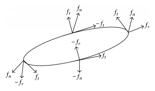
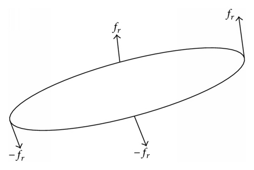
Step 1 (reduction of inclination). The thrust mode relies on mode 1 to reduce inclination by rational k, along with the simultaneous targeting of the semimajor axis and eccentricity. The thrust form is shown in Figure 7.
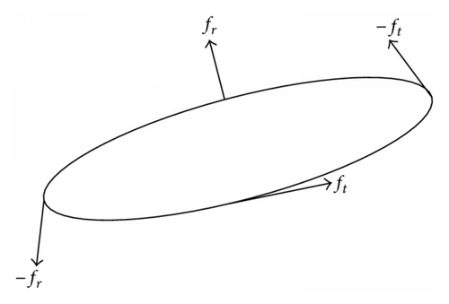
Step 2 (raising the semimajor axis). Mode 2 represents a law used to control the semimajor axis and the eccentricity when the inclination reaches the target value. The thrust operates as shown in Figure 8.
Step 3 (reducing eccentricity). While the semimajor axis reaches its target, ft remains at 0 to ensure the stability of the semimajor axis. fr is used to reduce eccentricity in mode 3, as illustrated in Figure 9.
Step 4. Mode 4 is the thrust model for Earth shadow, according to formula (9) to realize real-time judgment of shadow, in which thrust is 0.
Step 5. Mode 5 is used for the radar detection area to realize satellite low observability. The satellite adjusts to its best attitude, corresponding to thrust components fr = 0, fn = 0, and, if ep2 < 0, ft = f; otherwise, ft = 0, because ft = f contributes to both the decrease of eccentricity and the increase of the semimajor axis when ep2 < 0 (Figure 10).
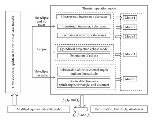
In short, the method described in this paper determines a control depending on a parameter and the state of current orbit. Our control law is simple, with only one uncertain control parameter, whose optimization is so convenient that our minimum-time transfer problem is greatly simplified.
5. Simulation
5.1. Initial Parameter
The ideal attitude of the satellite was assumed to have the range of its yaw angle, roll angle, and pitch angle as [−5∘, 5∘], [−5∘, 5∘], and [175∘, 185∘]. The yaw angle of each radar ranges from −60° to 60°, pitch angle ranges from 0 to 90°, and operating distance was 15,000 km. They were located in the following places (longitude/latitude): (65°E, 35°N), (30°E, 75°N), (75°E, 75°N), (120°E, 75°N), (165°E, 75°N), (15°E, 75°N), (60°W, 75°N), (105°W, 75°N), and (150°W, 75°N); (30°E, 75°S), (75°E, 75°S), (120°E, 75°S), (165°E, 75°S), (15°E, 75°S), (60°W, 75°S), (105°W, 75°S), and (150°W, 75°S); (30°E, 45°N), (75°E, 45°N), (120°E, 45°N), (165°E, 45°N), (15°E, 45°N), (60°W, 45°N), (105°W, 45°N), and (150°W, 45°N); (30°E, 45°S), (75°E, 45°N), (120°E, 45°S), (165°E, 45°S), (15°E, 45°S), (60°W, 45°S), (105°W, 45°S), and (150°W, 45°S); (30°E, 15°N), (75°E, 15°N), (120°E, 15°N), (165°E, 15°N), (15°E, 15°N), (60°W, 15°N), (105°W, 15°N), and (150°W, 15°N); (30°E, 15°S), (75°E, 15°S), (120°E, 15°S), (165°E, 15°S), (15°E, 15°S), (60°W, 15°S), (105°W, 15°S), and (150°W, 15°S).
The satellite’s initial mass m0 = 2600 kg was assumed to be equipped with four thrusters with a specific impulse of Isp = 1600 s and a maximum thrust of F = 80 mN. The GTO departure date was fixed as 1 June 2008 for shadow calculations. Table 2 displays the initial GTO and GEO boundary conditions.
| Orbit parameters | Initial orbit | Final orbit |
|---|---|---|
| GTO | GEO | |
| Semimajor axis a (km) | 24731 | 42164 |
| Inclination i (deg) | 28.5 | 0 |
| Eccentricity e | 0.7194 | 0 |
| Right ascension Ω (deg) | 1.7104 | Free |
| Argument of perigee ω (deg) | 179.6 | Free |
| Mean anomaly M (deg) | 2.9044 | Free |
5.2. Thrust and Control Angles
Figures 11 and 12 show the time-evolution of thrust and thrust control angles in the orbit transfer, in which Earth shadow and oblateness (J2) effects were considered with no low-observable constraint. In contrast, Figures 13 and 14 show results taking into consideration all of the aforementioned factors.
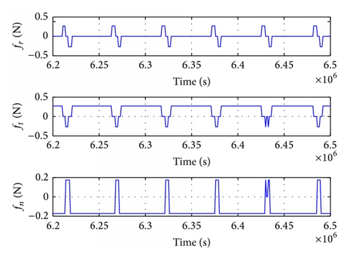
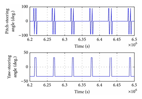
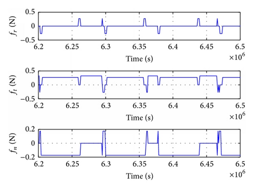
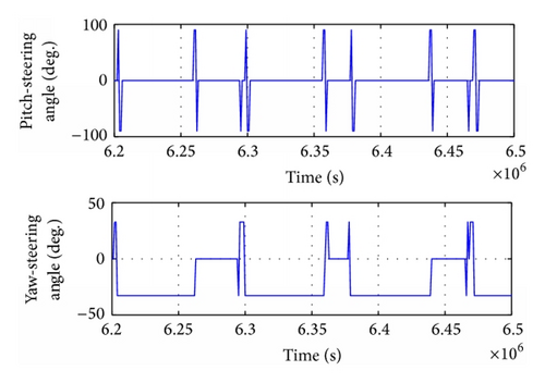
As can be seen in Figures 11–14, the satellite flew over the radar detection area three times in these six orbit periods, respectively, 6.263 × 10⁶ ~ 6.294 × 10⁶ s, 6.363 × 10⁶ ~ 6.377 × 10⁶ s, and 6.44 × 10⁶ ~ 6.465 × 10⁶ s. The thrust components were fr = 0, ft = f, and fn = 0. The thruster operated in mode 5 to maintain low observability of the satellite (Table 3).
| Start/stop time (s) | Total time (s) | Thrust componets N | Control angels | |
|---|---|---|---|---|
| 1 | 6.263 × 10⁶~6.294 × 10⁶ s | 3.1 × 10⁴ | fr = 0, ft = f, and fn = 0 | α = 0, β = 0 |
| 2 | 6.363 × 10⁶~6.377 × 10⁶ s | 1.4 × 10⁴ | fr = 0, ft = f, and fn = 0 | α = 0, β = 0 |
| 3 | 6.44 × 10⁶~6.465 × 10⁶ s | 2.5 × 10⁴ | fr = 0, ft = f, and fn = 0 | α = 0, β = 0 |
5.3. Numerical Results
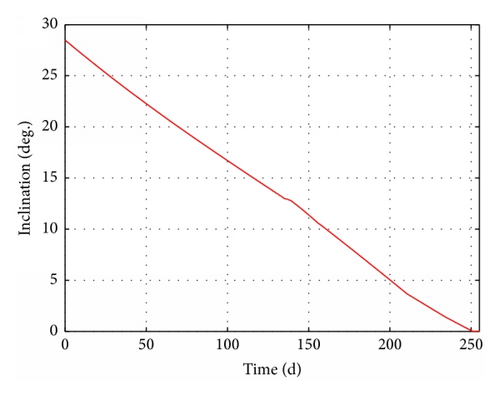
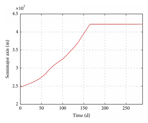
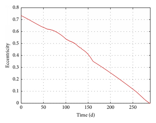
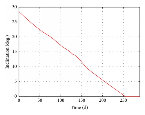
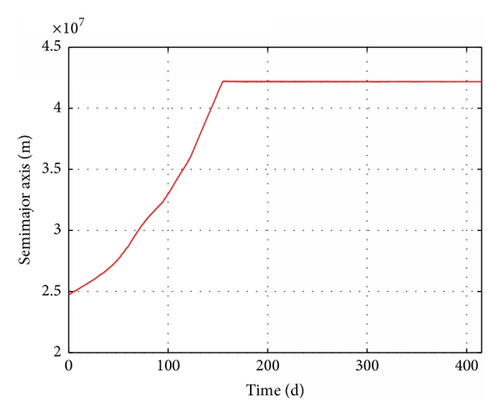
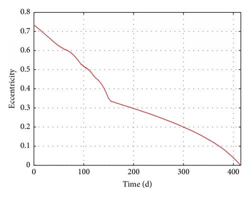
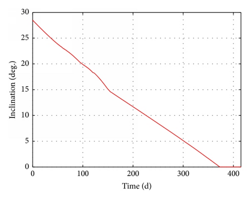
To demonstrate the validity of our proposed method, four scenarios are presented in Table 4. Case 1 represents a transfer based on the optimal control method l, using Pontryagin’s maximum principle to find the optimum control law [14]. Cases 2 and 3 represent transfers based on our method. Case 3 involves Earth shadow and oblateness (J2) effects. Cases 4 and 5 involve Earth shadow, oblateness (J2) effects, and low observability. Case 4 considers only one radar detection area (65°E, 35°N), while Case 5 includes other 48 areas.
| Mission | GTO → GEO | ||||
|---|---|---|---|---|---|
| Case 1 | Case 2 | Case 3 | Case 4 | Case 5 | |
| Fuel consumption Δm (kg) | 404 | 431 | 443 | 507 | 723 |
| Transfer days Δt (d) | 230 | 245 | 251 | 288 | 410 |
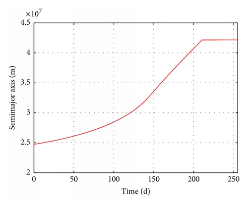
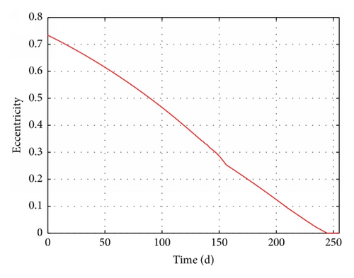
The results of these four cases are summarized in detail in Table 4. The time-evolution of state for Case 3 is presented in Figures 15–17. The time-evolution of state for Case 4 is shown in Figures 18–20. The time-evolution of state for Case 5 is presented in Figures 21–23. GTO-GEO transfer times were 230 days and 245 days for the optimal method and our method, respectively. Case 4 led to a 288-day transfer, requiring 507 kg of fuel. Case 5 was a 410-day transfer consuming 723 kg of fuel. Compared with the results of the optimal control, our method clearly offered performance near the results of optimal method with no ground estimation, was particularly flexible when orbit elements changed, and presented no two-point boundary problem and a low computational burden.
6. Conclusion
A new method based on control parameter analysis has been used to design a low-thrust orbit transfer. The optimization of the parameter introduced here is utilized to solve the optimal control problem. Satellite low observability was considered in GEO transfers, and the effects of Earth shadow and oblateness were also included in our method.
This approach possesses three important features: (1) The approach is characterized by simplicity and feasibility, on-board real-time solution, less calculation, and no initial guess for convergence, (2) the influence of Earth shadow and perturbation is taken into account, proving its strong fault tolerance, and (3) a simple but effective approach is used to achieve satellite low observability and reduce the threat of radar. In general, this trajectory method would serve as a useful preliminary design for GEO mission designers.
Conflict of Interests
The authors declare that there is no conflict of interests regarding the publication of this paper.
Acknowledgments
The paper is supported by the open funding project of State Key Laboratory of Virtual Reality Technology and Systems, Beihang University (Grant no. BUAA-VR-14KF-06) and National Natural Science Foundation of China (no. 61203188).


