Theoretical Simulation and Optimization on Material Parameters of Thin Film Bulk Acoustic Resonator
Abstract
The resonance frequency, fs, and the effective electromechanical coupling factor, , of thin film bulk acoustic resonators (FBARs) are derived by transfer matrix method. The effects of thickness and density of electrode on fs and with different piezoelectric layers are investigated by numerical calculation method. The results show that thickness and density of electrode affect fs obviously, especially in large thickness and density area. Moreover, the effects of thickness, density, and acoustic velocity of electrode on of FBAR were also studied. The results show that there is a maximum corresponding to the composition of thickness and density of electrode which is about 20% over the original electromechanical factor of piezoelectric film. is in the direct proportion to the density ρe and ve of electrode, respectively. The electrode thickness affects small with high ve; moreover, when ve is high enough, then has almost nothing to do with de. always rises with electrode thickness first and then descends with its rising, and the thickness corresponding to the maximum is different with different electrode, but it always locates in the special area. All above results indicate that the thickness, density, and acoustic velocity of electrode are so important that these results can be applied to design FBAR.
1. Introduction
The thin film bulk acoustic resonators (FBARs) are extensively applied for filters, resonators, and sensors, since they were first realized with the resonance frequency of 1.9 GHz in 1999, such as MEMS, biosensors, and gas sensors [1–8]. It is a kind of important device in electronic equipment, and so many kinds of FBARs with high frequency and small dimension have been fabricated during recent ten years for the demand of the industry [9, 10]. The FBARs are especially expected to be investigated and applied by many semiconductor companies such as Agilent, Philip, Murata, and TDK, because of their excellent merits.
Most of researchers focus on the fabrications and the applications of FBAR, and there also are a few researches about numerical simulation and optimization of FBAR. Chao et al. studied the electrode effects of FBAR by Butterworth-van Dyke (BVD) equivalent circuit [11], and Chen and Wang calculated the effective electromechanical coupling coefficient of FBAR [12], and Zhang et al. applied resonant spectrum method to characterize piezoelectric films in FBAR [13]. Besides, our research group published the research about the electrode effect of FBAR [14], and Naumenko analyzed the propagation of acoustic wave in FBAR with Finite Element Method [15], and Kvasov and Tagantsev calculated the nonlinear electrostrictive coefficient with first principles [16]. All of above researches aim at the excellent FBAR performance because the resonance frequency, the effective coupling coefficient, and the accurate optimization for the design of FBAR are the key points for FBAR performance.
As a kind of bulk acoustic resonator (BAR), the figure of merit of an FBAR can be defined by , and QS is the resonance quality factor which is obviously controlled by the piezoelectric layer and electrode effect, and the special research has been done by our research group [14], and so we deeply discuss the material parameter effects of electrode on the resonance frequency, the effective electromechanical coupling factor, and the theoretical optimization consideration of FBAR in this paper considering the regularity among the density ρe, the thickness de, the acoustic velocity ve of electrode, and the FBAR performance parameters fs and . The transmission matrix method was used in this research, and the following research points and corresponding simulation results are presented: (1) the transfer matrix method being used to derive the input impedance equation, (2) effects of ρe and de on fs, (3) effects of ρe and de on , (4) effects of ve and de on , and (5) the two cases with the piezoelectric films of ZnO and AlN, respectively, being compared for discussion.
2. Simulation Method and Procedures
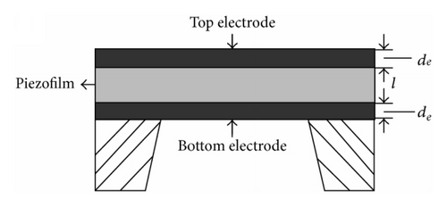
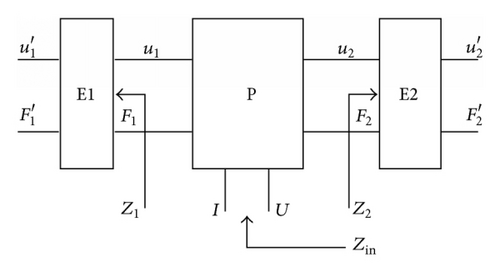
Based on the definition published in the IEEE Std. 176-1987 [17], fs is the frequency corresponding with the maximum conductance. Then fs can be calculated by (7), and can be evaluated by (8). However, is not only determined by but also closely related with the electrode and resonator structure.
So the resonance frequency and the effective electromechanical coupling coefficient of FBAR can be obtained and analyzed by above definitions and equations.
3. Effects of Material Quality Factors on Effective Coupling Factor
The effect of electrode on FBAR performance is studied and shown in the following parts, and the thickness, de, the density, ρe, on the resonance frequency, fs, and the effective electromechanical coupling factor, , are investigated; besides, the acoustic velocity ve on is also done. The different piezoelectric films of ZnO and AlN with thickness of 2 μm are used in this research, and they both are typical examples in the realistic applications, and the constants of material used in the calculation are shown in Table 1.
| Material | Density (kg/m3) |
Velocity (m/s) |
Impedance (106 kg/m3s) |
|
|---|---|---|---|---|
| ZnO | 5606 | 6350 | 35.6 | 7.50 |
| AlN | 3300 | 11050 | 36.5 | 6.25 |
3.1. Effects of ρe and de on fs of FBAR
The resonance frequency is very important parameter for frequency devices, especially for the acoustic device with vibration such as FBAR. In general, the frequency of FBAR is the basic parameter which should be considered during the design of FBAR, and so it is why we began with it.
The resonance frequency definitions are stated in the IEEE Std. 176-1987 that fs is defined as the frequency of maximum conductance [17]. So we can calculate fs by setting the conductance maximum with (7). In the calculations, we take the different piezoelectric films with ZnO and AlN and take all other parameters as constants except the density and the thickness of electrode. We can take the different density as different electrode material and study what will happen to the resonance frequency of FBAR if we change the thickness of the same material electrode, which is very valuable for the design of FBAR devices.
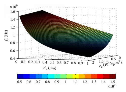
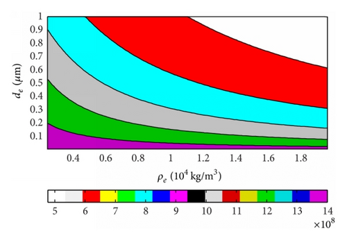
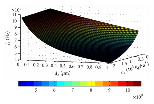
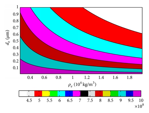
The results of fs changing with ρe and de of FBAR based on ZnO and AlN piezoelectric films were obtained, and the three-dimensional (3D) figures were shown as Figures 3(a) and 4(a), respectively, and the two-dimensional (2D) figures were shown as Figures 3(b) and 4(b), respectively. It can be obtained that the resonance frequency decreases with the thickness and the density of electrode increasing by the 3D figures, and this rule becomes more typical with the thin electrode or the high density, and it is the most obvious when both thickness and density of electrode appear in large value area. So we can choose proper material with small density and thin electrode for high resonance frequency by these results even though there still are some other parameters which should also be considered such as acoustic velocity. However, if the acoustic velocity in the electrode is a constant, then this result can be effectively used to design and evaluate the resonance frequency according to the application requirement. The above results can also be proved by the two 2D figures. Besides, we also can get that the FBAR decreased over half of resonance frequency just with the thickness change of 0.4 μm, and so the thickness effect of electrode on the resonance frequency are very distinct, which becomes smoother in the smaller thickness area.
3.2. Effects of ρe and de on of FBAR
Based on the definition published in the IEEE Std. 176-1987 [17], fs is the frequency of maximum conductance and fp is the frequency of maximum resistance. Then fs and fp can be calculated by (7), and can be evaluated by (8). is not only determined by but also determined by the electrode and resonator structure.
We calculated changing with the thickness and the density of electrode, and the 3D figures and 2D figures were given in Figures 5 and 6 with ZnO and AlN piezoelectric films, respectively.
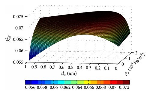
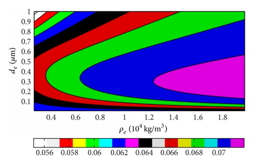
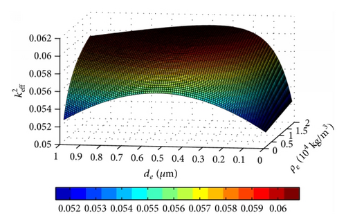
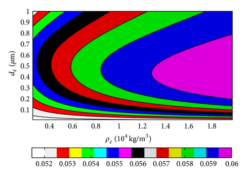
It can be obtained by Figures 5(a) and 6(a) that there is the maximum corresponding to some compositions of thickness and density of electrode, which is near the thin electrode and high density area. increases and then decreases with the thickness increasing, and the increasing ratio can reach to 20% over original value of piezoelectric film. However, mostly increases with the density of electrode. changes fast with the thickness of electrode when the density of electrode is small, and vice versa. The FBAR with the ZnO layer shows that changes more quickly than the case of AlN, and the thickness effect is more obvious too, especially for the small density of electrode cases. Furthermore, we can also get the same witness from the 2D figures of Figures 5(b) and 6(b).
A very interesting result is obtained from 2D figures that will arrive at a maximum area with special thickness values for any density of electrode, and the corresponding thickness area is very obvious at the center, such as the FBAR with ZnO. The thickness beginning with the maximum area is nearby 0.37 μm, and the thickness is nearby 0.5 μm for the AlN case. This is a very interesting and important result, and it means the effect of thickness on has a strong rule which is affected little by the density of electrode material. We analyzed this phenomenon that it is the thickness where standing wave appears, and the difference between these two piezoelectric film cases should be attributed to the different piezoelectric thin films. Moreover, it confirms that the standing wave exists in the FBAR, and the thickness of electrode should be optimized with this merit point, which is effective for all kinds of electrode materials.
3.3. Effects of ve and de on of FBAR
For overall evaluation of , the effects of ve and de on were conducted with the 2 μm thick piezoelectric film, and the 2D and 3D figures with four different electrode density choices were given for contrasting. The 3D versus ve and de curves based on ZnO and AlN were shown in Figures 7 and 9, respectively, and the 2D results were shown in Figures 8 and 10 correspondingly. The key parameters and results were marked on the 3D figures. We can get that always rises with the density of electrode for the ZnO case in Figure 7 which also can be observed in above section results, and the maximum always appears at the maximum acoustic velocity during our calculation range. The AlN case is the same behavior as the ZnO FBAR in Figure 9. Moreover, rises more obviously with ve in the large electrode thickness area and vice versa, and changes little with ve among the small electrode thickness area and especially least in the high density electrode material area. On the other hand, rises distinctly with the electrode thickness in the low velocity area, but it almost does not change in the high velocity space.
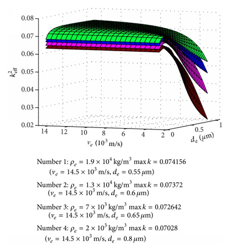
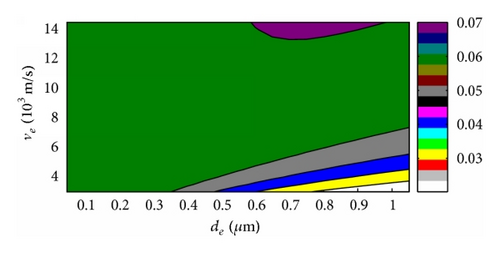
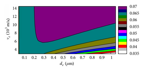
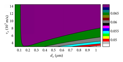
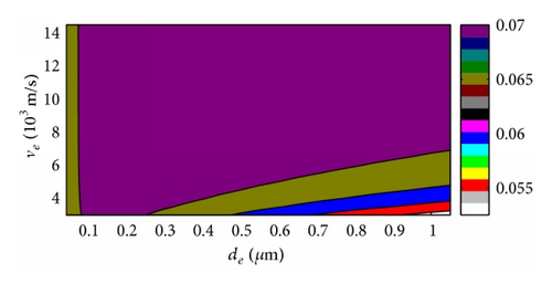
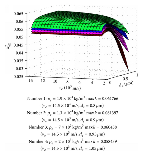
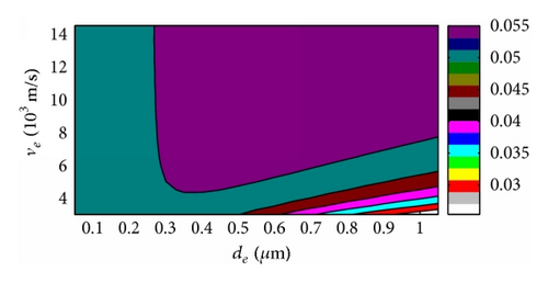
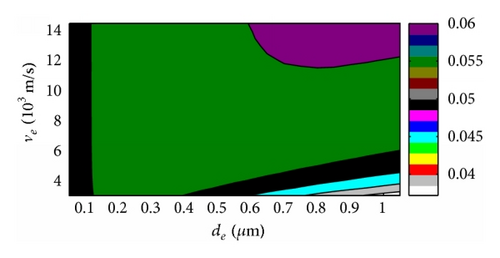
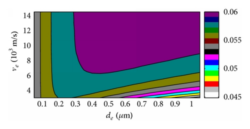
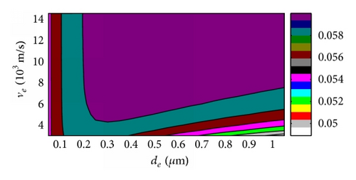
We can conclude that is in the direct proportion to the density ρe here, and the acoustic velocity of electrode has a similar effect too, and dominantly rises with ve. The electrode thickness affects small with high ve; moreover, when ve is high enough, then has almost nothing to do with de. But changes fast with de when ve is small, and rises with electrode thickness first and then descends with its rising, which was also observed in the former section. The thickness corresponding to the maximum is different with different electrode density; however, it descends with density ascending, which also proves the special value ρede corresponding with the maximum of FBAR even though we cannot get this result directly by these figures because there are not so many piezoelectric film parameters considered for proving [14]. All these behaviors are similar for both ZnO and AlN based FBARs.
The density, acoustic velocity, and thickness of electrode of FBAR can be optimized by above results for special fs and need. We can get the higher with the higher electrode density, and it is also the same to acoustic velocity of electrode material. The best thickness of electrode is decided by density and especially acoustic velocity; however, the thickness effects are obvious when the acoustic velocity is small, but it almost does not change if the acoustic velocity is very big. Moreover, the best thickness corresponding to the maximum is different with different cases, but the values are in the special area comparing with the distinctly variable ve and ρe, and it is because we take most of the parameters of piezoelectric thin film as constants, even though these results can be observed in both ZnO and AlN FBARs in this research.
4. Conclusions
- (i)
Firstly, we derived the input acoustic impedance equation with transfer matrix method, and the simplified impedance equation of FBAR with the same top and bottom electrode is obtained. This equation can be applied extensively to calculate the resonance frequency, the effective electromechanical coupling factor, the mechanical quality factor, and the merit figure of FBAR, which makes the theoretical calculation and optimization easy.
- (ii)
Secondly, the effect of thickness and density of electrode on the resonance frequency of FBAR was investigated, and it can be obtained that the thickness and the density of electrode affect the resonance frequency obviously, especially at the large thickness and density area. This result shows that the thickness and the material of electrode are very key parameters for the resonance frequency design of FBAR.
- (iii)
Finally, the effects of thickness, density, and acoustic velocity on the effective electromechanical coupling factor were studied, respectively. The results show that is in the direct proportion to both density ρe and ve of electrode. The electrode thickness affects small with high ve; moreover, when ve is high enough, then has almost nothing to do with de. rises with electrode thickness first and then descends with its rising, and the thickness corresponding to the maximum is different with different electrode density and ve, but they almost locate in the special area.
All above results indicate that the thickness, density, and acoustic velocity of electrode are very important, and they can be applied to optimize and design different kind of FBARs.
Conflict of Interests
The authors declare that there is no conflict of interests regarding the publication of this paper.
Acknowledgments
This work is supported by the National Natural Science Foundation of China (nos. 61201088, 11404257, and 11504291), Shaanxi Province Innovation Project for Science and Technology Overall Planning (no. 2012KTCL01-12), Industrialization Foundation of Shaanxi Educational Committee (no. 2011JG10), and Xi’an Technology Transferring and Promoting Project (CXY1342(5), CX1253(2)).


