Control System Design for a Ducted-Fan Unmanned Aerial Vehicle Using Linear Quadratic Tracker
Abstract
Tracking control system based on linear quadratic (LQ) tracker is designed for a ducted-fan unmanned aerial vehicle (UAV) under full flight envelope including hover, transition, and cruise modes. To design the LQ tracker, a system matrix is augmented with a tracking error term. Then the control input can be calculated to solve a single Riccati equation, but the steady-state errors might still remain in this control system. In order to reduce the steady-state errors, a linear quadratic tracker with integrator (LQTI) is designed to add an integral term of tracking state in the state vector. Then the performance of the proposed controller is verified through waypoint navigation simulation under wind disturbance.
1. Introduction
A ducted-fan UAV is tactically useful for a battlefield. In particular small military units can operate this UAV for various missions such as reconnaissance, surveillance, and communication relay because it has capability of hovering without a runway. Also, it has unlimited hovering capability to land on the top of building in the battlefield or urban area without concerning weather conditions or fuel consumption. The ducted-fan vehicle also has aerodynamic advantages to generate more lift by the duct effect than unducted-fan configuration [1]. Moreover, the UAV has shrouded configuration by duct, which is good for mobility and operator safety. The duct can improve the rotor safety by protecting from foreign object damages. In addition, unlike normal VTOL UAVs, it is easy to transit to cruise flight with regard to operating speeds. The ducted-fan UAVs can also be designed in a variety of sizes from micro to medium. However, the ducted-fan UAV is inherently an unstable system, and each axis is dynamically coupled multiple-input multiple-output (MIMO) system. Furthermore, this vehicle is too sensitive to overcoming wind disturbance because the duct generates drag by crosswind. Therefore, the operation of the ducted-fan UAVs is limited by weather condition. In order to cope with these circumstances, a robust control system should be considered for autonomous flight.
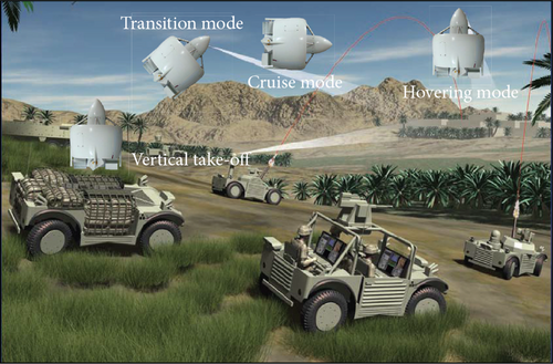
The ducted fan has capabilities of fixed wing and vertical take-off and landing (VTOL) UAVs as the above-mentioned flight features. Also, operation modes can be classified by three modes as hover, transition, and cruise modes. Therefore, an operation concept takes these advantages into account. For instance, the vehicle vertically takes off from an unmanned ground vehicle (UGV) or a military jeep and goes up to proper altitude, when the ducted-fan UAV is operated in the battlefield for a reconnaissance mission. Then, the mode is changed from the hover through the transition to the cruise mode during this climbing phase. When this UAV reaches the operation area for the mission, the flight mode is changed to the hover mode as shown in Figure 1.
Control methods for the ducted-fan type UAV are researched in various places. One of the effective approaches to control this vehicle is based on a nonlinear control theory [2–9]. Hess and Ussery proposed a sliding mode control (SMC) with the feedback linearization for a linearized six-degree-of-freedom model to consider a hover flight, and the robustness of the applied controller was verified via waypoint simulation [2]. Spaulding et al. researched a nonlinear dynamic inversion control system for a small scale ducted-fan UAV during the mode changes from hover to forward flight [3]. Moreover, dynamic model inversion (DMI) with neural network to provide an adaptive controller is studied by Johnson and Turbe for the GTSpy, based on the Micro Autonomous Systems’ HeliSpy. The performance of the controller was evaluated via flight tests [4]. In addition, a backstepping technique is researched to improve robustness of control system [5, 6]. Pflimlin et al. designed a nonlinear controller based on the backstepping techniques that stabilize position of the HoverEye in crosswind condition at hover mode [5]. Aruneshwaran et al. proposed a neural adaptive backstepping controller for the ducted-fan type UAV. The proposed controller considered unknown nonlinearities, unmodeled dynamics, and wind disturbance. The performance was evaluated by using numerical simulation [6]. Naldi et al. applied nonlinear control law and experimentally validated it in a hover flight condition to use a small scale prototype [7]. Also, Marconi et al. studied the problem of dynamic modeling and controlling the ducted-fan miniature UAV to consider explicitly interaction with the external environment [8]. In the presence of external disturbances, adaptive positon-tracking controllers were researched by Roberts and Tayebi [9]. Also, a fuzzy logic is applied for this type’s vehicles [10, 11]. Takagi-Sugeno fuzzy gain-scheduler and PD controller were applied by Lee and Bang for the HeliSpy model. The control scheme was validated via a waypoint guidance simulation for hover flight [10]. Also, a fuzzy logic controller was proposed by Omar et al. for a ducted-fan VTOL UAV with fixed wing to cope with transition manoeuvre to consider wind disturbance [11]. Moreover, linear control method is studied based on a classical controller with an optimal control theory. Shin et al. developed a position control scheme of a small flying robot which has the ducted-fan type configuration. A PD controller was designed for an attitude system, and a linear quadratic integrator (LQI) was designed for a hovering control. Then the designed control system was verified indoor flight test [12].
In this research, a tracking controller based on an optimal control theory is proposed considering entire flight conditions: hover mode, transition mode, and cruise mode for the Chungnam National University (CNU) ducted-fan UAV that has been developed. In order to reduce steady-state error, linear quadratic tracker with integrator (LQTI) is designed to augment an integral term of the tracking state in the state vector to be suitable for the highly coupled system. The proposed controller can reduce computation power compared to the compensator method with neural network adaptation law [4, 6]. Moreover, the LQTI is designed for an attitude control to compare with the linear approach [12]. In addition, to guarantee reality of the controller design, this study presents extensive modeling and trim/linearization analysis of the CNU ducted-fan UAV by carrying out wind tunnel tests. They are performed with a wind tunnel velocity from 0 m/s to 15 m/s to cover the full flight modes against the previous studies to consider hovering operation [2, 5, 6, 9, 10, 12]. Also, the robustness against wind disturbances is validated through numerical simulations.
This paper is organized as follows. Section 1 describes the background and motivation of the paper and summarizes the related researches on controller algorithms for the ducted-fan type UAVs. Section 2 presents dynamic equations of motion of the CNU ducted-fan UAV briefly. Section 3 covers the tracking controller based on the optimal control theory and deals with an augmented tracker to use an integral control element. Section 4 reports the numerical simulation results of the tracking and three-dimensional waypoint cases. Finally, Section 5 concludes the paper.
2. Dynamic Modeling
A configuration of the CNU ducted-fan UAV is introduced in this section. Also, precise linearized modeling data of the UAV at each flight condition is established using mathematical approach which is divided into three modes with respect to airspeed: hover mode (0 m/s), transition mode (5 and 10 m/s), and cruise mode (15 m/s).
2.1. Configuration and Coordinate System
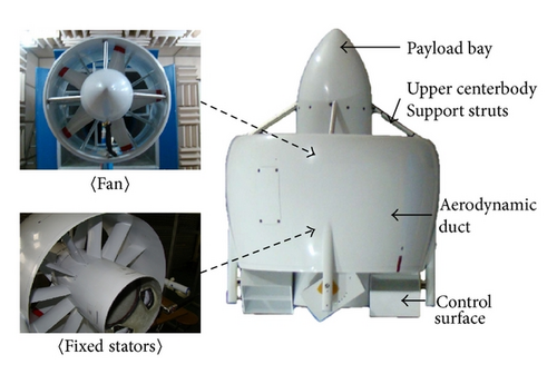
A configuration of the CNU ducted-fan UAV is conventional ring-wing type as shown in Figure 2. It has four control surfaces that are located at the end of the duct. Also, it contains fixed stators for reducing an antitorque effect and additional lift. A fuselage is in center of the vehicle, and avionics are mounted in the duct or the fuselage. In addition, payload bay is placed on top of the fuselage. For various missions, operating equipment such as camera and spot light and communication relay can be located at this bay.
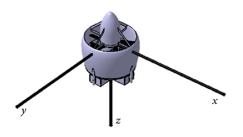
A coordinate system shown in Figure 3 has dynamic features similar to a helicopter: thrust vector, antitorque effect, gyroscopic coupling, and velocity induced by a main rotor. Pitch angle and angle of attack are zero at hover flight: as the vehicle goes forward, it becomes negative [13]. In addition, moment of inertia is completely the same about x-axis and y-axis because of symmetricity.
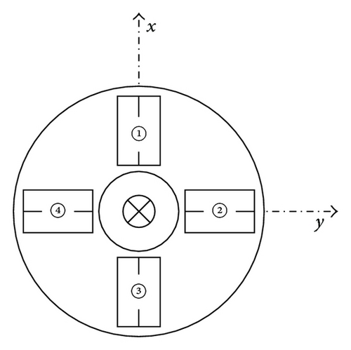
The control surfaces are defined in Figure 4: the control surfaces 1 and 3 are ailerons, 2 and 4 are elevators, and deflecting all of control surfaces are rudders. These deflect from −30 to +30 degrees. The sign convention of the control surfaces angle is set to “+” for generating positive moment as indicated in Table 1.
| Flaps | Deflection | Sense | Effect |
|---|---|---|---|
| ①, ③ | Trailing edge left | +δail | +L |
| ②, ④ | Trailing edge down | +δele | +M |
| ①, ②, ③, ④ | Trailing edge counterclockwise | +δrud | +N |
2.2. Dynamic Equations
2.3. Trim Analysis
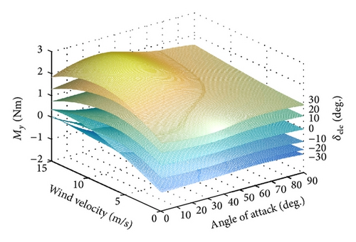
In order to measure total force and moment on the body axis of the CNU ducted-fan UAV, the wind tunnel test results are used in this study. The tests perform with a wind tunnel velocity from 0 m/s to 15 m/s, which includes full flight modes. Figure 5 represents the pitching moment of the vehicle at 4,500 RPM [13]. However, the wind tunnel test could not be experimented over the operating RPM because structural problems occurs by a strong vibration when the RPM exceeds 4,500. Therefore, an interpolation technique is applied for getting data over 4,500 RPM.
Figures 6 and 7 show the interpolated wind tunnel test data to compare with numerical data by the modeled dynamics [14]. These comparison results show that a precise dynamic modeling is constructed from the force and moment analysis.
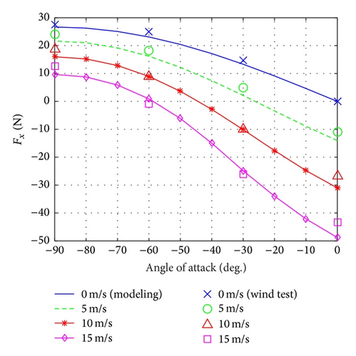
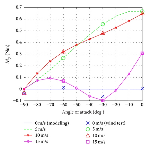
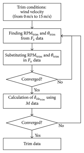
In this research, the trim point is defined as 0, 5, 10, and 15 m/s, and each speed denotes hover, transition, and cruise flight modes. The mathematical trim results are calculated by the gradient method based on nonlinear dynamic equations as described in Section 2.2. Moreover, the trim conditions from the wind tunnel test are determined using iteration of its data. Figure 8 shows the process of the trim calculation of the wind tunnel test. The trim states are obtained for both mathematical modeling and wind tunnel tests, which are summarized in Table 2. The mathematical modeling shows similar tendency to the experimental data. The trim pitch angle θtrim is generally assumed to be zero in a conventional UAV for linearization. However, the trim pitch angle of the ducted-fan UAV is too significant to ignore during the full flight envelope. Thus, θtrim is considered as nonzero in the state-space equation. Then linear models are extracted by using a small-disturbance theory for the trim condition of each operating mode as indicated in Table 2. Also, the linearized models from hover mode to cruise flight mode are applied to design the control system based on the optimal control theory in Section 3.
| V (m/s) | RPM | θ (deg.) | δele (deg.) | |
|---|---|---|---|---|
| Wind tunnel test | 5 | 5880 | −16.98 | −9.46 |
| 10 | 5844 | −39.34 | −9.76 | |
| 15 | 5752 | −54.02 | −4.26 | |
| Mathematical modeling | 5 | 5907 | −23.94 | −8.35 |
| 10 | 5647 | −40.32 | −8.47 | |
| 15 | 5602 | −51.47 | −4.10 | |
3. Optimal Control System Design
The optimal controller is designed for the CNU ducted-fan UAV which, as mentioned in Section 1, is a highly coupled MIMO system. A linear quadratic regulator (LQR) has been shown to be efficient and relatively simpler than classical control system design to apply to the MIMO system. This section briefly describes the optimal control theory. Next, the tracking problem is introduced since the desired output is not zero. A linear quadratic tracker (LQT) is designed for the tracking problem, but the steady-state error may occur. To reduce the steady-state error, a linear quadratic tracker with integrator (LQTI) is proposed for the CNU ducted-fan UAV.
3.1. Optimal Control Theory
3.2. Linear Quadratic Tracker
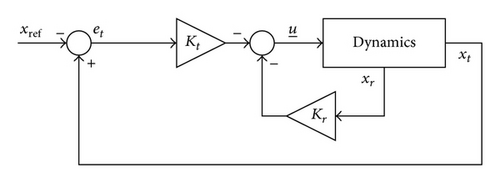
Theorem 1. Let CLQTI be any matrix so that . Suppose (AΣ, CLQTI) is observable; then (AΣ, BΣ) is controllable if and only if
- (1)
there is a unique positive definite limiting solution S(∞) to the Riccati equation; furthermore, S(∞) is the unique positive definite solution to the algebraic Riccati equation;
- (2)
the closed-loop plant equation (17) is asymptotically stable, where K = K(∞).
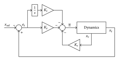
4. Numerical Simulations
The simulations are separated into two cases. Firstly, a speed tracking control is designed by using LQT and LQTI based on the optimal control theory and performed in Case 1. Then waypoint guidance simulation is carried out to evaluate the performances under wind disturbances in Case 2. Both cases are considered for a real experimental platform which has a GPS receiver, gyro sensors, and a magnetic sensor to acquire state data. The angular rates (p, q, and r) and the Euler angles (ϕ, θ, and ψ) are measured using the gyro sensors and the magnetic sensor. Moreover, the velocities (u, v, and w) can be determined by using GPS speeds (Vx, Vy, and Vz) and the Euler angles. The simulation environment is built with the Matlab/Simulink and sampling time is 0.02 sec.
4.1. Case 1: Speed Tracking Control
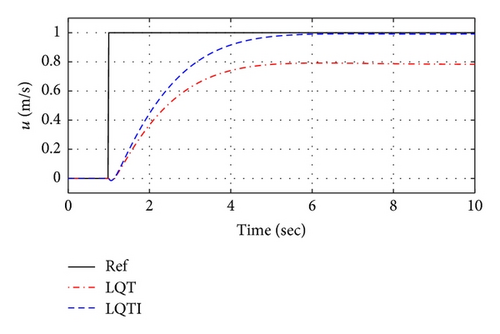
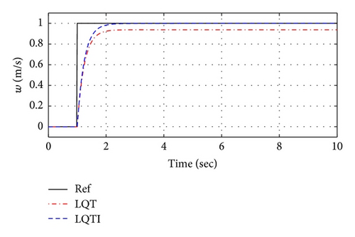
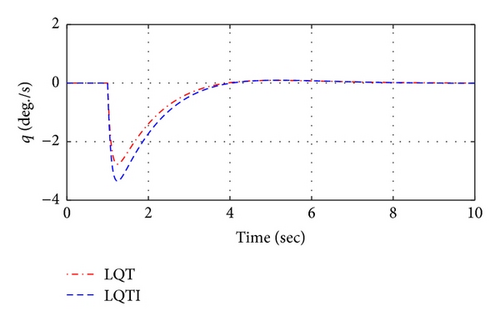
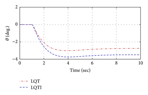
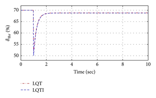
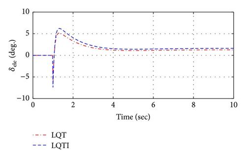
The simulation Case 1 represents a step response of the tracking variables and compares tracking performance between the LQT and LQTI methods. Figures 11 and 12 show the simulation results based on the LQT and LQTI methods. Figure 11 shows comparison results between controllers for the states histories of the UAV. The LQT has the steady-state errors to the tracking commad, but the LQTI can reduce the steady-state errors as shown in Figure 11. In addition, control inputs of both controllers are shown in Figure 12.
4.2. Case 2: Waypoint Navigation
The waypoint navigation is simulated over the entire flight conditions in a three-dimensional space. The control system consists of the proportional-integral-derivative (PID) and LQTI controllers as shown in Figure 13. The proposed LQTI controller is applied for attitude control, and the PID controller is used for the trajectory tracking for an outer loop.

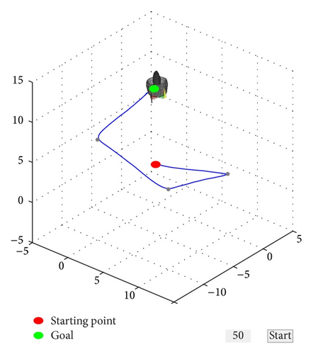
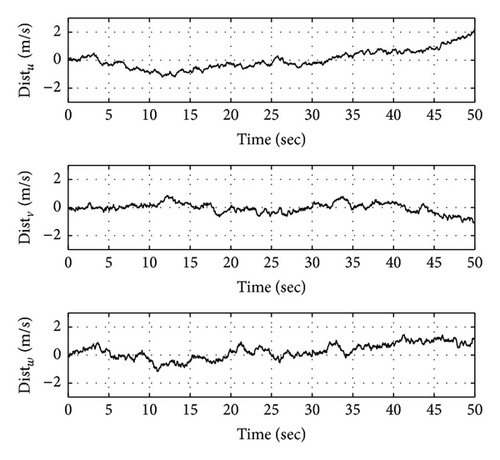
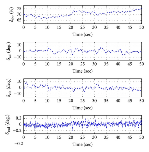
Moreover, wind disturbance is considered for this simulation to verify the performance of the proposed controller. The Dryden wind turbulence model is used for the disturbance as shown in Figure 15.
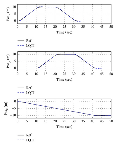
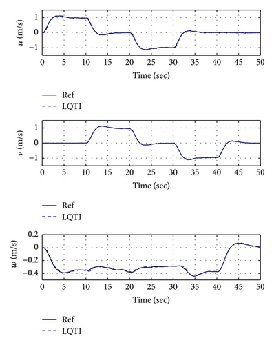
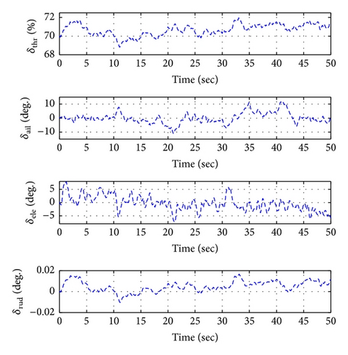
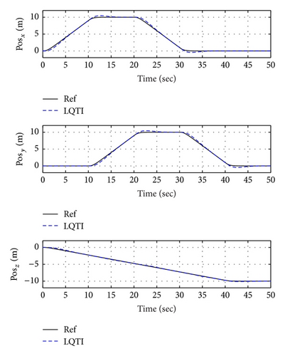
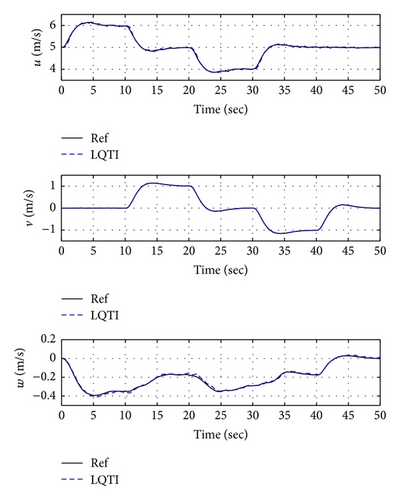
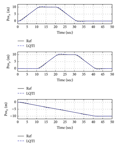
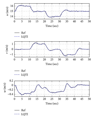
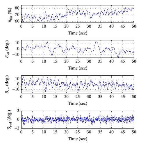
Figures 16, 19, and 22 show x-y-z axis position histories of each flight condition. The vehicle approaches each waypoint accurately. Figures 17, 20, and 23 show time histories of the velocity. Control inputs of this simulation are shown in Figures 18, 21, and 24, respectively. In conclusion, the simulation results show that the proposed controller (LQTI) has good tracking performance and proper control consumption even if wind disturbance exists.
5. Conclusions
In this research, the control system was designed for the ducted-fan type UAV because this system is inherently unstable and dynamically coupled. The tracking controller based on the optimal control theory was applied considering entire flight modes for the CNU ducted-fan UAV under unknown disturbance. In order to construct the precise dynamic modeling, the basic dynamics were modified by using the wind tunnel test data, and the modified model was verified to compare the wind test and numerical modeling results. Also, the trim analysis was carried out for the linearization of the dynamic equations to design of the optimal tracker. Then, the LQ tracker was derived to extend LQR design procedure based on the linearized model. However, the basic LQ tracker cannot eliminate the steady-state error. In order to cope with the steady-state error, the integral element was augmented based on the LQ tracker structure. The designed controllers were verified via numerical simulations which were sorted into two cases. The longitudinal simulation was performed in Case 1 to compare between the LQT and LQTI controllers. This simulation result showed that the LQTI controller reduced the steady-state error. Then, the LQTI controller has better tracking performance than the LQT controller. In addition, the three-dimensional waypoint navigation was simulated under the entire flight envelope which includes hover, transition, and cruise flight modes in Case 2. Additionally, the robustness against wind disturbances is validated through numerical simulations as well. The result of the second simulation shows a feasibility of the LQTI controller to be used for the operation of the ducted-fan UAV.
The proposed controller will be applied for an experimental system. In addition, a numerical solution will be applied to solve the Riccati equation to implement the LQTI for flight tests. Also, an observer will be designed to improve the control performance. Then, the procedures and results including modeling, trim/linearization analysis, and optimal control design in this study will be devoted to further theoretical study for ducted-fan UAVs and putting them to practical use.
Conflict of Interests
The authors declare that there is no conflict of interests regarding the publication of this paper.
Acknowledgments
The authors gratefully acknowledge the financial support by Agency for Defense Development under Unmanned Technology Research Center (UV-32) and International Joint Research Programme (UD130001HD).


