A New Approach in Pressure Transient Analysis: Using Numerical Density Derivatives to Improve Diagnosis of Flow Regimes and Estimation of Reservoir Properties for Multiple Phase Flow
Abstract
This paper presents the numerical density derivative approach (another phase of numerical welltesting) in which each fluid’s densities around the wellbore are measured and used to generate pressure equivalent for each phase using simplified pressure-density correlation, as well as new statistical derivative methods to determine each fluid phase’s permeabilities, and the average effective permeability for the system with a new empirical model. Also density related radial flow equations for each fluid phase are derived and semilog specialised plot of density versus Horner time is used to estimate k relative to each phase. Results from 2 examples of oil and gas condensate reservoirs show that the derivatives of the fluid phase pressure-densities equivalent display the same wellbore and reservoir fingerprint as the conventional bottom-hole pressure BPR method. It also indicates that the average effective kave ranges between 43 and 57 mD for scenarios (a) to (d) in Example 1.0 and 404 mD for scenarios (a) to (b) in Example 2.0 using the new fluid phase empirical model for K estimation. This is within the k value used in the simulation model and likewise that estimated from the conventional BPR method. Results also discovered that in all six scenarios investigated, the heavier fluid such as water and the weighted average pressure-density equivalent of all fluid gives exact effective k as the conventional BPR method. This approach provides an estimate of the possible fluid phase permeabilities and the % of each phase contribution to flow at a given point. Hence, at several dp′ stabilisation points, the relative k can be generated.
1. Introduction
Several sets of well and reservoir models have been generated with pressure derivatives with different boundary conditions. Likewise, several type curves, which account for different combinations of wellbore, reservoir characteristics, and boundary effects with associated flow regimes for computation of well and reservoir parameters, have been used to simplify well test interpretation. This demonstrates that the log-log plot of the pressure derivative is a powerful tool for reservoir model identification in pressure transient analysis.
However, in practice, each current method of transient data analysis has its own strengths and limitations with no single pressure and production data analysis method capable of handling all types of data and reservoir types with clear reliable results [1]. The log derivative and derivative type curve, which have remained reference flow regime’s diagnostic tools for over four decades, are the only unified approach for welltest interpretation and are applicable in a wide range of situations.
The derivative method, which is the greatest breakthrough in welltest analysis, was first introduced by Tiab in 1976 [2, 3] and developed by French mathematician Dominique Bourdet in 1983 [4]. It has remained the reference solution for identifying flow regime, boundary response, and use for diagnosing complex reservoir features till date. This approach has helped to reduce the uncertainties surrounding the interpretation of welltest data because key regions of radial flow and boundary features have been adequately diagnosed. However, due to the nonunique solution of the mathematical fluid flow equation, mostly in heterogeneous reservoir, most engineers in the industry are compelled to use analytical model and type curve solutions to match complex model, which is oftentimes not realistic. Assumptions made are ignored while pursuing a perfect match and results obtained from this approach are often misleading [5].
This marked the beginning of numerical well testing in the industry by Zheng, 2006 [5], although the approach started from the early 1990s [6–10]. Zheng made more advances in 2006, providing more solutions to the nonunique problems mostly in heterogeneous reservoirs through numerical welltesting, thereby promoting its application. More papers have been published by researchers on the subject, thereby reflecting the advancement of numerical welltesting and its application in solving various reservoir engineering practical problems.
One of the main limitations of the pressure derivative is that the measured pressure data must be constructed into derivative data, by means of numerical differentiation. Oftentimes derivative data from real field are very noisy and difficult to interpret, resulting in various smoothing techniques developed by researchers on this subject. It is practically believed that smoothing of pressure derivative data often alters the characteristics of the data. Also, it is difficult to distinguish between fluid and reservoir fingerprints in critical saturated reservoirs.
Another limitation of these derivatives is diagnosing flow regimes in complex reservoir structures such as complex faulted systems and high permeability streak with interbedded shales, which is common in deep water turbidite systems, channel-levee, lobe, and channelized deposits. Also, in situations of multiphase flow around the wellbore, the derivative data are always noisy and difficult to interpret, resulting in the application of deconvolution and various smoothing techniques to obtain a perceived representative model which often might not be. Additionally, the analytical solution for transient pressure analysis is limited to single phase flow, which in real case is never the situation. Presently there are few literatures or research on multiphase transient pressure analysis. However, the combination of the new statistical approach [11] and the density derivative approach serves as a support tool for better interpretation and estimation of reservoir properties in these conditions.
The diagnosis of flow, which appears as distinctive patterns in the pressure derivative curve, is a vital point in welltest interpretations since each flow regime reflects the geometry of the flow streamlines in the tested formation. Hence, for each flow regime identified, a set of well and/or reservoir parameters can be estimated using the region of the transient data that exhibits the characteristic pattern behaviour [11]. In the study, the pressure derivative formulation from Horne (1995) [12] and the new statistical approach by Biu and Zheng (2015) [11] would be used throughout the analysis.
Model 1. Consider the following:
Model 2 (the exponential function). Consider the following:
Model 3. Consider the following:
2. Theoretical Concept of the Density Derivatives
- (i)
conservation of mass equation,
- (ii)
transport rate equation (e.g., Darcy’s law),
- (iii)
equation of state.
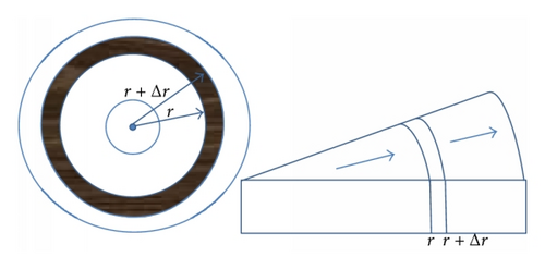
Over the decades, the transient test analysis has applied the general diffusivity equation in pressure term to generate several nonunique solutions using several pressure-rate data.
3. Software Suitability (Pressure Equivalent)
To apply the numerical density approach in existing software, the pressure equivalent of the fluid density changes at the wellbore is generated from the relationship below.
3.1. For Small or Constant Compressibility Fluid Such as Oil and Water
3.2. For Compressible Fluid in Isothermal Conditions
Also, outside the available welltest software, the pressure derivative can be generated from the pressure equivalent obtained from the oil, gas, and water densities at the well by applying (1) formulated by Horne (1995) [12] or (2) to (4) by Biu and Zheng (2015) [11].
4. Density Weighted Average (DWA)
4.1. Empirical Model Correlation between Fluid Phases K
With the estimation of the phase’s permeabilities, it is therefore possible to estimate the possible relative permeability to each phase and the percentage contribution to flow by each phase at one point analysis; hence, at several points, the relative k can be generated.
To illustrate applicability of this approach, 6 scenarios in conventional oil reservoir and gas condensate reservoir are investigated using numerical model built with a commercial simulator. Local grid refinement (LGR) is imposed around the well to capture sharp change in fluid densities as shown in Figure 2.
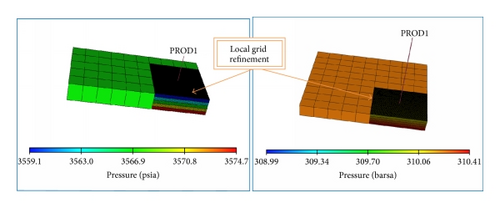
The simulation software keywords LBPR, LDENO, LDENW, LDENG AND WBHP were outputs to obtain the density and pressure change around the well and as far as the perturbation could extend.
Example 1. Table 1 presents a summary of the well and reservoir synthetic data used for the buildup and drawdown simulated scenarios with additional information given below. It is required to generate the pressure equivalent and derivative for each phase, compare their diagnostic signatures, and also determine the phases permeabilities and average reservoir permeability.
| Parameters | Design value |
|---|---|
| Eclipse model | Black oil |
| Model dimension | 10 × 5 × 5 |
| Length by width, ft by ft | 500 × 400 |
| Thickness h, ft | 250 |
| Permeability Kx by Ky, mD | 50.0 by 50.0 |
| Porosity % | 20 |
| Well diameter, ft | 0.60 |
| Initial water saturation Swi, % | 22 |
| Permeability, K, mD | 50 |
| Gas oil contact (GOC), ft | 8820 |
| Oil water contact (OWC), ft | 9000.0 |
| Initial pressure, Pi, psia | 4000.0 |
| Formation temperature, T, oF | 200.0 |
Assumption. (i) Oil reservoir + gas cap is completed with one well.
(ii) LGR is imposed around the well and far across to account for pressure and density changes.
- (a)
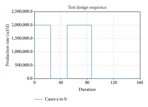
Flowing + buildup sequence: well perforated hp = 30 ft between oil and water layer. Net sand thickness h = 250 ft.
- (b)
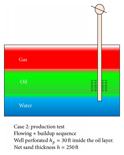
Flowing + buildup sequence: well perforated hp = 30 ft inside the oil layer. Net sand thickness h = 250 ft.
- (c)
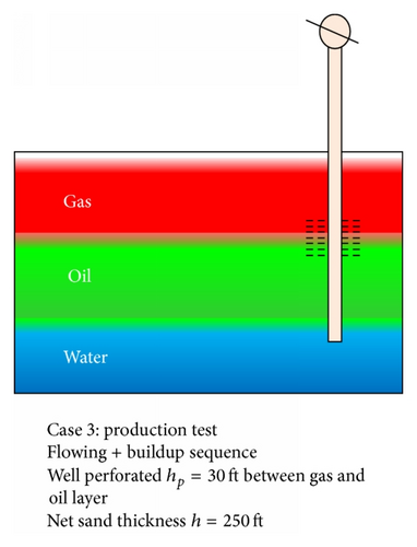
Flowing + buildup sequence: well perforated hp = 30 ft between gas and oil layer. Net sand thickness h = 250 ft.
- (d)
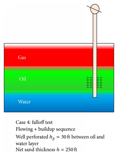
Falloff test; flowing + buildup sequence: well perforated hp = 30 ft inside the oil layer. Net sand thickness h = 250 ft.
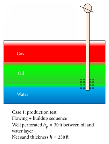
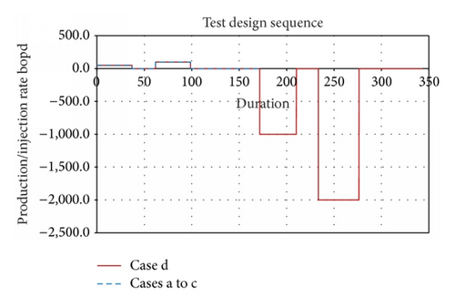
In scenario (a), the well is completed between the oil and water layer to mimic multiphase conditions at the wellbore and some distance away from the well and also see the effect on pressure distribution, fluid densities changes around the wellbore, and estimate fluid phase permeabilities k using the specialised plot and kave from the empirical model for three-phase conditions.
The derivative in Figure 6 shows a good radial flow but drop in derivative at late time due to constant pressure support (likely aquifer support). A continuous drop is seen from 10 hrs in the model parameters. The derivatives for all output parameters display the same well and reservoir signatures (3 flow periods, early to late time response) but with different dp′ stabilisation. The well bottom-hole pressure (BPR → BHP) response shows good overlay with pressure equivalent of density weighted average (PDENDWA → PDENA) and pressure equivalent of water density (PDENWAT → PDENW) while pressure equivalent of gas density (PDENGAS → PDENG) and pressure equivalent of oil density (PDENOIL → PDENO) differ completely. The PDENDWA gives a better fingerprint that is less noisy.
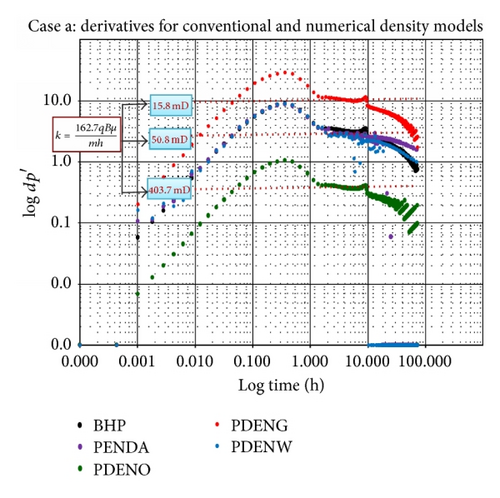
A permeability value of 50.8 mD is estimated from the bottom-hole pressure BPR where k = 162.7qBμ/mh and m is obtained from the specialised plot. This is an approximate of the input value in the simulation model. Also the simulator outputs PDENDWA and PDENWAT in the simulation give the same k value while PDENGAS and PDENOIL differ, giving 15.8 and 403.7 mD, respectively. At h = 50 ft, the best k estimate is obtained depicting h = 50 ft as the thickness contributing to flow. At h > 50 ft, k drops below the k imputed in the model.
Using (34), kave = 47.3 mD is obtained, which is approximately close to that of BPR, hence a good estimate of the fluid phase permeabilities. A summary of the result is shown in Tables 2 and 5.
| Parameters | Numerical density k (mD) |
Equivalent h (ft) |
|---|---|---|
| BHP | 50.8 | |
| PDENA | 50.8 | |
| PDENG | 15.8 | 50 |
| PDENO | 403.7 | |
| PDENW | 50.8 |
In scenario (b), the well is completed within the oil section to capture the pressure and fluid densities changes around the well. The derivative in Figure 7 shows a good radial flow but with noisy numerical artefact. It is likely that the boundary response is masked by numerical artefact. Also a continuous drop is seen after 10 hrs in the derivative.
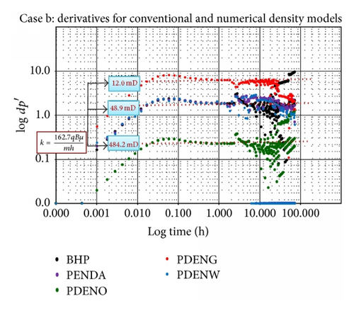
Using the estimated fluid phase permeabilities, kave from (34) is 47.2 mD as shown in Table 3, which is the same as scenario (a). This is in line with the uniform k used in the simulation model. Also the BPR gives a permeability value of 50.0 mD, which is the same for PDENDWA and PDENWAT but differs with PDENGAS and PDENOIL that give 12.1 and 484.4 mD, respectively. At h = 150 ft (60% of sand thickness and 83% of oil thickness), the estimated k is still within range (k = 48.9 mD). This indicates h = 50 ft or 83% of oil thickness contributing to flow.
| Parameters | Numerical density k (mD) |
Equivalent h (ft) |
|---|---|---|
| BHP | 50.0 | |
| PDENA | 50.0 | |
| PDENG | 12.1 | 50 |
| PDENO | 484.2 | |
| PDENW | 50.0 |
To test this approach in the gas column, the well was completed in between the gas and oil layer, which is considered as scenario (c) and scenario (d) with the well completed within the oil layer but with water injection after flowing and shut-in sequence. In both scenarios, the multiphase fluid distribution is triggered at the wellbore in order to capture the density changes for each phase and calculate fluid phase permeabilities. First, the well fluid densities equivalent pressures and pressures at bottom-hole for flowing and buildup test are generated.
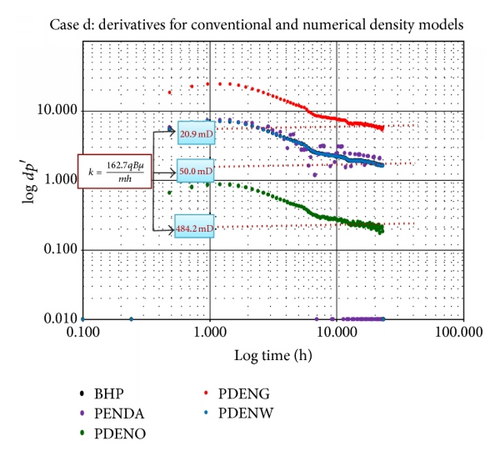
The derivative for both scenarios declines after 3 hours probably due to fluid redistribution but is noisy (numerical artefact) in scenario (c) as shown in Figure 8. A good radial stabilisation for both the conventional method BPR and the density outputs PDENDWA, PDENWAT, PDENGAS, and PDENOIL is observed. Likewise, as obtained in scenarios (a) and (b), a good Kave value of 57 and 52 mD from (34) is obtained for scenarios (c) and (d), respectively. This is slightly higher than k = 50 mD imputed in the simulation model.
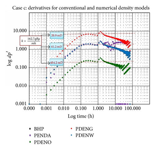
For each of the fluid phase permeabilities estimates, k value of 50 mD is obtained using the conventional BPR for scenario (c), which is in line with the uniform k in the simulation model. This is the same for the PDENDWA and PDENWAT. Also, at h = 150 ft (60% of sand thickness and 83% of oil thickness), the estimated k is still within range (k = 41.2 mD). This also indicates that h = 150 ft or 83% of oil thickness is contributing to flow. The k values for PDENGAS and PDENOIL are 20.9 and 484.2 mD, respectively. Summary of the result is shown in Table 4.
| Parameters | Numerical Density k (mD) | Equivalent h (ft) | |
|---|---|---|---|
| Scenario (d) | BHP | 50.0 | 100 |
| PDENA | 50.0 | ||
| PDENG | 17.5 | 50 | |
| PDENO | 490 | 250 | |
| PDENW | 50.0 | 100 |
| Scenario | Numerical density method | Calculated K (mD) |
Conventional k (mD) |
Simulation model K (mD) |
Relative K | % phase contribution to flow |
|
|---|---|---|---|---|---|---|---|
| Phases | K (mD) | ||||||
| (a) | Gas | 15.8 | 0.03 | 3.0 | |||
| Oil | 403.7 | 47.3 | 50.8 | 50.0 | 0.86 | 86.0 | |
| Water | 50.8 | 0.11 | 11.0 | ||||
| (b) | Gas | 12 | 0.03 | 2.0 | |||
| Oil | 484.4 | 43.2 | 50.0 | 50.0 | 1.13 | 89.0 | |
| Water | 50 | 0.12 | 9.0 | ||||
| (c) | Gas | 20.9 | 0.04 | 4.0 | |||
| Oil | 484.2 | 57.0 | 50.0 | 50.0 | 0.86 | 87 | |
| Water | 50 | 0.09 | 9.0 | ||||
| (d) | Gas | 17.5 | 0.03 | 3.0 | |||
| Oil | 490 | 52.3 | 50.0 | 50.0 | 0.95 | 88.0 | |
| Water | 50 | 0.10 | 9.0 | ||||
However, in scenario (d), the permeability value of 50.0 mD using the conventional BPR, which is the same for PDENDWA and PDENWAT, is only achieved if h = 100 ft (40% of sand thickness and 56% of oil thickness). PDENGAS and PDENOIL differ, giving 35.0 mD at h = 50 ft and 196.0 mD at h = 250 ft, respectively. This indicates the impact of water injection on densities and pressures changes around the well and consequently its impact on sand thickness contributing to flow. The drop in derivative curve in Figure 9 depicts the impact of the injected water.
In summary, for scenarios (a) to (d), the k value of 50.0 mD is achieved if the thickness contributing to flow ranges from 50 to 150 ft. Generally, results indicate that, in all 4 scenarios investigated, the heavier fluid such as water and the weighted average pressure-density equivalent of all fluid give exact effective k as the BPR, likewise the density outputs PDENDWA and PDENWAT. Also results from Table 5 show that the empirical model from (34) with all fluid phase permeabilities gives an average effective kave of 47–57 mD, which is within that used in the simulation model and also the same as the estimated conventional approach. This approach provides an estimate of the possible fluid phase permeabilities and the % of each phase contribution to flow; hence, at several points, the relative k can be generated as shown in Table 5.
Example 2. To capture the influence of highly compressible fluid on estimated fluid phase permeabilities, an example on gas condensate reservoir (volatile system) was tested. Table 6 presents a summary of the well and reservoir synthetic data used for the buildup and drawdown simulated scenarios with additional information given below. It is required to generate the pressure equivalent and derivative for each fluid phase, compare their diagnostic signatures, and also determine the phases permeabilities and average reservoir permeability.
| Parameters | Design value |
|---|---|
| Eclipse model | Black oil |
| Model dimension | 9 × 3 × 3 |
| Length by width, ft by ft | 1312 × 984 |
| Thickness h, ft | 150 |
| Permeability Kx by Ky, mD | 400.0 by 300.0 |
| Porosity, % | 30 |
| Well diameter, ft | 1.15 |
| Initial water saturation Swi, % | 60 |
| Permeability, K, mD | 400 |
| Gas oil contact (GOC), ft | 6890 |
| Oil water contact (OWC), ft | 6890 |
| Initial pressure, Pi, psi | 4495 |
| Formation temperature, T, °C 120 | 200.0 |
Assumption. (i) Condensate reservoir is completed with one well.
(ii) LGR is imposed around the well and far across to account for pressure and density changes.
- (a)
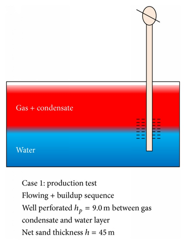
Flowing + buildup sequence: well perforated hp = 30 ft between gas condensate and water layer. Net sand thickness h = 150 ft.
- (b)
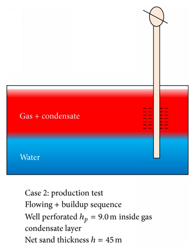
Flowing + buildup sequence: well perforated hp = 30 ft inside gas condensate layer. Net sand thickness h = 150 ft.
As in Example 1, the derivative in scenario (a) of Example 2 also shows good radial flow with no late time effect as seen in Figure 11. A negative half-slope fingerprint is seen at 0.3 to 3.0 hrs of buildup and a good stabilisation from 4.0 hrs in the model parameters.
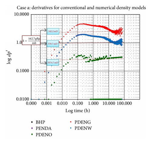
The derivatives for all output parameters display the same well and reservoir fingerprint (2 flow periods, early to middle time response) but with different dp′ stabilisation.
Permeability value of 370.7 mD was obtained from the conventional method BPR where k = 1637qT/mh is the same for the PDENDWA and PDENWAT, and m is obtained from the specialised plot. This is in line with the uniform k (kx = 400 mD and ky = 300 mD) imputed in the simulation model. However PDENGAS and PDENOIL differ, giving 35.0 mD and 3574.7 mD, respectively, if h = 148 ft.
Also the derivative in Figure 12 shows good radial flow and a negative half-slope fingerprint is seen at 0.5 to 2.0 hrs of buildup and a good stabilisation from 3.0 hrs in the model parameters. After 3 hrs of shut-in, some noisy data (numerical artefact) is seen in all the fluid phase derivatives but still good enough to identify dp′ stabilisation.
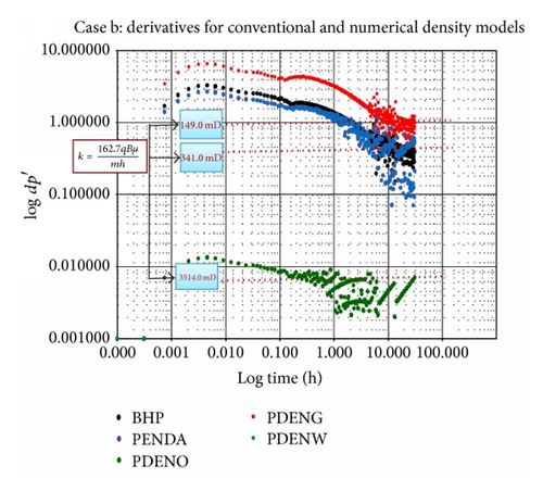
For each of the fluid phase permeabilities, k value of 340.9 mD at h = 148 ft is obtained using BPR, which is the same for the PDENDWA and PDENWAT. PDENGAS and PDENOIL differ, giving 149.0 and 3514.1 mD at h = 148 ft, respectively.
For scenarios (a) and (b), a good kave value of 405.0 and 403.0 mD is obtained, respectively, from the empirical model (34) integrating all fluid phase permeabilities, which is within that used in the simulation model and the estimated conventional approach. From the 2 scenarios investigated, it has been demonstrated that the heavier fluid such as water and the weighted average pressure-density equivalent of all fluid give exact effective k as the conventional method BPR. A summary of the result is shown in Table 7.
| Parameters | Numerical density k (mD) |
Equivalent h (ft) |
|
|---|---|---|---|
| Scenario (a) | BHP | 371 | |
| PDENA | 371 | ||
| PDENG | 142 | 148 | |
| PDENO | 3575 | ||
| PDENW | 371 | ||
| Scenario (b) | BHP | 341 | |
| PDENA | 341 | ||
| PDENG | 149 | 148 | |
| PDENO | 3514 | ||
| PDENW | 341 | ||
This approach estimates the fluid phase permeabilities and the % of each phase contribution to flow at a given point; hence at several points the relative k can be generated as shown in Table 8.
| Scenario | Numerical density method | Calculated K (mD) |
Conventional k (mD) |
Simulation model K (mD) |
Relative K | % phase contribution to flow |
|
|---|---|---|---|---|---|---|---|
| Phases | K (mD) | ||||||
| (a) | Gas | 142.2 | 0.04 | 3.0 | |||
| Oil | 3574.7 | 404.6 | 370.7 | 400 | 0.89 | 87.0 | |
| Water | 370.7 | 0.09 | 9.0 | ||||
| (b) | Gas | 149 | 0.04 | 4.0 | |||
| Oil | 3514.1 | 403.8 | 340.9 | 400 | 0.89 | 88.0 | |
| Water | 340.9 | 0.08 | 9.0 | ||||
5. Density Related Radial Flow Equation Derivation for Each Fluid Phase
5.1. From Equation for Slight and Small Compressibility Such as Water and Oil
Apply boundary conditions as follows.
For 1/4x > 25, consider the following.
5.2. For Water Phase
5.3. For Gas Phase
From equation for compressible fluid such as gas, consider the following.
For 1/4x > 25, consider the following.
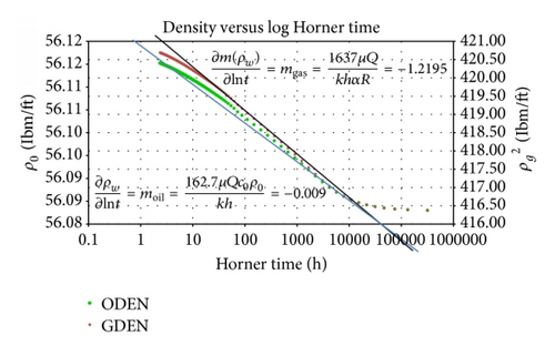
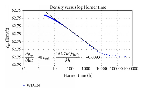
Example 3. Data from Example 1(a) was used for this case and the semilog plot of density for each phase (oil, water, and gas) is plotted against log of Horner time.
∗∗Q used for k calculation is the average rate for all flowing periods.
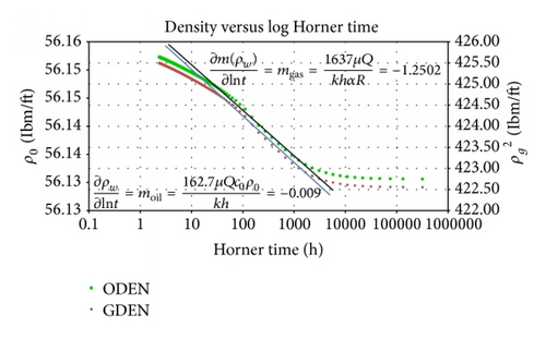
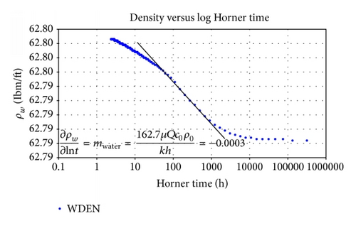
Example 4. Data from Example 1(c) was used for this case and the semilog plot of density for each phase (oil, water, and gas) is plotted against log of Horner time.
From Figures 15 and 16, the calculated slopes of the radial flow for oil and water phases are given as
6. Conclusion
- (i)
Results from the three-phase fluid empirical model developed for average effective kave estimation range between 47 and 57 mD for Example 1 and give 404 mD for Example 2, which is within that used in the simulation model and also estimated from BPR.
- (ii)
The BPR, PDENDWA, and PDENWAT give the same stabilisation and the same k estimates making it suitable for interpretation of pressure transient analysis.
- (iii)
It has been demonstrated in all 6 scenarios investigated that the heavier fluid such as water and the weighted average pressure-density equivalent of all fluid give exact effective k as the conventional method.
- (iv)
For oil reservoir system (scenarios (a) to (d)), k = 50.0 mD is achieved if the thickness contributing to flow ranges from 50 to 150 ft while, for gas condensate reservoir (scenarios (a) to (b)), k ranges between 340 and 371 mD which is achieved if the net sand thickness h = 148 ft is contributing to flow.
- (v)
This approach also provides an estimate of the possible fluid phase permeabilities and the % of each phase contribution to flow at a given point; hence, at several dp′ stabilisation points, the relative k can be generated.
- (vi)
The derivatives for all output parameters display the same wellbore and reservoir fingerprint as the BPR method.
- (vii)
Generally, where output parameters (BPR, PDENOIL, PDENGAS, PDENWAT, and PDENDW) depict different fingerprint, the density derivative will serve as support to distinguish between reservoir and nonreservoir response.
Nomenclature
-
- P:
-
- Pressure, psi
-
- T:
-
- Temperature, oF
-
- r:
-
- Radius, ft
-
- k:
-
- Permeability, mD
-
- Ø:
-
- Porosity fraction
-
- µ:
-
- Viscosity, cp
-
- t:
-
- Time, hrs
-
- q:
-
- Production rate, bbl/day
-
- B:
-
- Formation volume factor, rb/Stb
-
- Ct:
-
- Total compressibility, psi−1
-
- rw:
-
- Wellbore radius, ft
-
- Δp:
-
- Change in pressure, psia
-
- h:
-
- Formation thickness, ft
-
- A:
-
- Drainage area acres
-
- Pwf:
-
- Bottom-hole flowing pressure, psi
-
- Pi:
-
- Initial pressure, psi
-
- Z:
-
- Difference between two point/time series
-
- i:
-
- Subscript of an observed variable
-
- c:
-
- Subscript of a calculated variable
-
- STEYX:
-
- SSE of data point
-
- n:
-
- Number of data points
-
- Cov:
-
- Covariance of data point
-
- δ:
-
- Standard deviation
-
- tp:
-
- Cumulative production time
-
- Cs:
-
- Wellbore storage constant
-
- :
-
- Mean of data point.
Abbreviations
-
- LBPR:
-
- Local grid bottom-hole pressure
-
- LDENO:
-
- Local grid oil density
-
- LDENW:
-
- Local grid water density
-
- LDENG:
-
- Local grid gas density
-
- WBHP:
-
- Well bottom-hole pressure
-
- BPR:
-
- Well bottom-hole pressure
-
- PDENOIL:
-
- Pressure equivalent of LDENO
-
- PDENGAS:
-
- Pressure equivalent of LDENG
-
- PDENWAT:
-
- Pressure equivalent of LDENW
-
- PDENDWA:
-
- Pressure equivalent of density weighted average (LDENO, LDENG, and LDENW).
Conflict of Interests
The authors declare that there is no conflict of interests regarding the publication of this paper.


