Development of Thermal Models and Analysis of UO2-BeO Fuel during a Loss of Coolant Accident
Abstract
Small fraction of high conductivity BeO in UO2 fuel significantly improves thermal conductivity and also affects the overall performance of the fuel during steady state operation and during transients. In this study, performance of UO2-BeO composite under transient conditions such as loss of coolant accident (LOCA), using FRAPTRAN (fuel rod analysis program transient), was carried out. The subroutines in FRAPTRAN code that calculate key thermophysical properties such as thermal conductivity, specific heat capacity, and specific enthalpy were modified to account for the presence of the BeO in UO2. The fuel performance parameters like gas gap pressure, energy stored in fuel, and temperature profiles were studied. The simulation results showed reductions in fuel centerline temperatures and lower temperature drop across fuel rod cross-section under normal fuel operations. It was observed that there was reduction in gas gap pressure and energy stored in fuel. Transient conditions involving cladding rupture were investigated and important performance parameters such as cladding strain were studied. During these transients, the addition of BeO to UO2 fuel seems beneficiary.
1. Introduction
Commercial nuclear reactors use uranium oxide, UO2, as a nuclear fuel. It is being used as a common nuclear fuel due to ease in its fabrication and good performance. However, it has a low thermal conductivity in the range of 2–8 W-m/K for temperature range from room temperature to 1000°C with decreasing value at high temperatures. There are efforts to increase its thermal conductivity by addition of compounds like BeO [1] and SiC. UO2-BeO composite has better temperature stability when compared to UO2-SiC. Many studies have been taken up to study the performance UO2-BeO fuel. The BeO is chosen as high thermal conductivity material in UO2 because in the nuclear fuel materials the BeO has been found to be most compatible for the UO2 fuel as an additive to enhance the thermal conductivity. BeO has one of the highest thermal conductivity ceramics and can withstand the radiation environment and does not react with UO2 up to 2200°C. This study focuses on studying the performance of UO2-BeO using FRAPTRAN (fuel rod analysis program transient).
FRAPTRAN is a fuel performance code used to calculate the response of single fuel rods to operational transients and hypothetical accidents at burnup levels up to 62 gigawatt-days per metric ton of uranium (GWd/MTU) [2, 3]. This code is typically used for analyzing fuel rod response to transients and accidents like reactivity induced accident (RIA) and loss of coolant accident (LOCA) for pressurized water reactor (PWR) and boiling water reactor (BWR).
Studies pertaining to UO2-BeO fuel started early, right from the 1960s. Irradiation behavior of UO2-BeO fuel as a function of fuel-particle size was studied by Johnson and Mills [4] in a program undertaken at General Atomic as a part of Experimental Beryllium Oxide Reactor Program to study the relative high temperature performance of BeO-UO2 containing 30% vol UO2 present in the form of fine and coarse particles. It was observed that greater quantity of Kr was released from fuel pellets containing coarser particles than finer ones. In a study by Titus and Saling [5] on the performance of two particular compositions of UO2-BeO composite, namely, 70% and 80% wt UO2, it was found that cladding of the one with 80% suffered severe swelling due to rupture. Performance of 70 wt% UO2-BeO was considered to be suitable for use in ML-1 reactor.
In a study taken up by Freed et al. [6] on development of UO2-BeO fuels, experiments were run with different compositions of UO2-BeO fuel in the range 30–60% vol UO2. They reported test results like cladding swelling and fission gas release for the composite fuel at different ranges of burnup. In the studies mentioned, it can be noted that the composition of BeO is higher than what is being taken up in the current work (~10 vol % BeO in UO2). There has been significant research on UO2-BeO fuel in this composition range too. Ishimoto et al. [7] studied the thermal conductivity of UO2-BeO pellet (0.3, 0.6, 0.9, 1.2 and 13.6 wt% BeO) and they concluded that there is a significant enhancement of thermal conductivity with BeO addition and that it was more for continuous type than the dispersed phase.
Latta et al. [8] focused on modeling and measurement of thermal properties of ceramic composite fuel for light water reactors. They used a finite element analysis computer program, ANSYS, to simulate thermal modeling of fuel composites consisting of BeO and SiC as secondary phases (0–15% wt) dispersed in UO2 matrix. The results from thermal modeling were also verified with experimental results. McCoy and Mays [9] studied the fuel performance and neutronics of enhanced thermal conductivity nuclear fuel with BeO. They took up two compositions of the composite (4% and 9.6% vol BeO) along with pure UO2. COPERNIC fuel rod performance code was used for their simulations and they observed reduced temperatures, internal rod pressures, and fission gas release, even with modest (5–10%) increases in thermal conductivity. Here, the performance of UO2-BeO composite is studied under transient conditions, using FRAPTRAN. Revankar and Zhou [10] performed thermal analysis of the UO2-BeO composite fuel using analytical models, CFD calculations, and RELAP5 code analysis. The fuel considered for this was developed using method developed by Sarma et al. [11] using green granules method.
2. FRAPTRAN Code and Validation
2.1. FRAPTRAN Code
FRAPTRAN [2, 3] is a transient single rod code that can calculate thermal quantities such as radial temperature profile and fission gas release to the gap and mechanical quantities such as creep deformation and irradiation growth. The range of models and correlations included in these codes is quite similar to that for the steady state codes like FRAPCON. The major difference is that, being a transient analysis code, it does not include long-term phenomena like creep. Also, it does not have models correlations and properties for cladding plastic stress-strain behavior at elevated temperatures, effects of annealing, behavior of oxides and hydrides during temperature ramps, phase changes, and large cladding deformations such as ballooning. The mechanical description of the cladding is two-dimensional ideally, but one-dimensional models are used as well.
- (i)
heat conduction;
- (ii)
cladding stress and strain;
- (iii)
rod internal gas pressure.
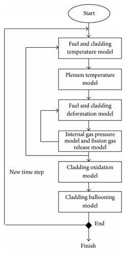
FRAPTRAN uses the standard material properties package MATPRO, same as that used by FRAPCON or RELAP. Simulating the performance of UO2-BeO was done by modifying a few subroutines that calculate thermophysical properties in FRAPTRAN.
2.2. Thermal Conductivity
2.3. Thermal Expansion
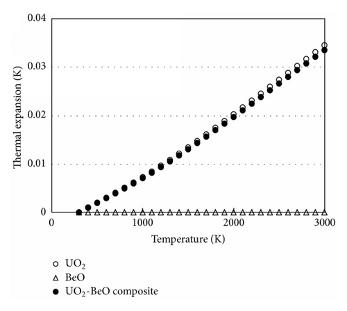
Thermal expansion of the fuel is calculated in the subroutine “fthexp.f.” Thermal expansion can be defined as dimensional changes in unirradiated fuel pellets caused by changes in temperature. These dimensional changes are critical as they affect the pellet to cladding gap size, which is a major factor in determining gap heat transfer and thus stored energy, an important parameter for safety analysis.
2.4. Specific Heat
2.5. Specific Enthalpy
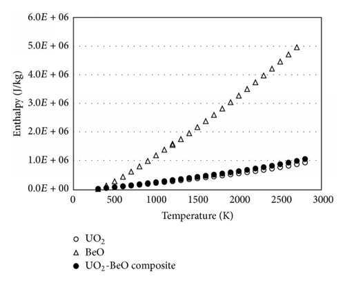
2.6. Code Model Validation
Validation of the code was carried out with material test case MT-4. This case consists of 12 full-length PWR rods subjected to adiabatic heatup followed by reflood. A preconditioning phase for the nonirradiated test rods was conducted for this test with water cooling at a pressure of 8.27 MPa and a flow rate of 16.3 kg/s. Two short runs to full power were made under these conditions to permit the fuel pellets to crack and relocate. Three transients were run prior to the actual test for MT-4 (designated MT-4.04). These transients were for reflood calibration and were assuring that the correct powers were used to obtain the desired cladding heatup rate of ~8.3 K/s. In the desired transient (MT-4.04), there was a short heatup phase of approximately 1.5 minutes and a longer phase at temperature that lasted approximately 20 minutes. Reflood was initiated 57 seconds after steam flow was shut off. The axial power input is in the form of a chopped cosine curve.
Results obtained from this simulation were compared to those discussed in FRAPTRAN assessment. They are also compared to the experimental results obtained. Table 1 illustrates this. In the table, we find that the results obtained are almost identical to the FRAPTRAN results reported in FRAPTRAN assessment.
| Parameter | Value | |
|---|---|---|
| Rupture time (s) | Measured | 55 (52–58) |
| FRAPTRAN assessment | 42.5 | |
| Current simulation | 30 | |
| Rupture location (m) | Measured | 2.68 |
| FRAPTRAN assessment | ~2 | |
| Current simulation | 2.286 m | |
| Rupture hoop strain % | Measured | 72 |
| FRAPTRAN assessment | 22 at node 7 | |
| Current simulation | 19.5 | |
Materials test-1 was conducted in the National Research Universal (NRU) reactor by the US Nuclear Regulatory Commission (NRC) with an objective to perform simulated LOCA. In this case, first the existing steam in the core is discharged. After some time interval reflood water enters the core. However due to overheating of the rods occurs while steam is discharged and increase in rod internal pressure occurs leading to fuel rod rupture with leakage of fission gases. With this as the primary case whose input deck was available in the user manual of FRAPTRAN, input decks for three other cases were created, each having different input coolant conditions. The dimensions of the fuel rod and the heat input profile were all retained, however.
3. Description of Test Cases
Four different case studies were performed with two different fuels: UO2 and UO2-BeO (10% vol) fuel rods. The three test cases, Case 1, Case 2, and Case 2(a), are steady state cases. The materials test-1 (MT-1) was transient case which was conducted in the National Research Universal (NRU) reactor by the US Nuclear Regulatory Commission (NRC) with an objective to perform simulated LOCA.
With MT-1 as the primary case whose input deck was available in the user manual of FRAPTRAN, input decks for three other cases were created, each having different input coolant conditions. The dimensions of the fuel rod and the heat input profile were all retained, however. Descriptions of these cases are briefly given below. Fuel rod specifications for MT-1 case are shown in Table 2.
| Parameter | Value |
|---|---|
| Pellet outer diameter | 8.26 × 10⁻³ m |
| Cladding | |
| Inner diameter | 8.41 × 10⁻³ m |
| Outer diameter | 9.63 × 10⁻³ m |
|
3.66 m |
The fuel rod was divided into twelve nodes in the axial direction each node at a distance of 1 ft. In the axial direction, linear heat input is given in form of a cosine curve. In the radial direction, the heat input was given uniformly.
-
heat rate was taken as 15.5 kW/m = 5.256 kW/ft;
-
coolant flow rate = 2.67e6 lb/ft2-hr;
-
system pressure = 2250 psi;
-
coolant inlet temperature = 565 F corresponding inlet enthalpy of 566 BTU/lb was given;
-
coolant outlet is also in the liquid state, that is, below saturation (in a single phase).
Case 2. In this case, with the same conditions as in Case 1, except that the inlet is two-phase coolant, the inlet temperature is at saturation (~618 K). Corresponding fuel enthalpy is calculated and given in the input deck. For this case, the coolant temperature is always a constant and quality alone increases.
Case 2(a). As an extension to the previous case, mass flux from the previous case alone is lowered and kept as low as possible to avoid cladding elastic strain rates becoming high. This was done so that the coolant gets heated up quickly forming steam somewhere at the midheight of the fuel rod.
MT-1. Ambient pressure in this case is very less, about 40 psi. Initially, there is steam at very high enthalpy (1273 BTU/lb). Flow of steam is also less, 9.72e4 lb/ft2-hr. The initial steam coolant empties after 10 seconds and reflooding occurs 32 seconds later. Reflood water has a temperature as shown in Figure 10. Flow rate of the reflood water is constant at 2 in/s.
4. Discussion of Results
4.1. Radial Temperature Profiles
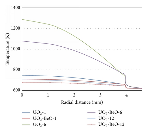
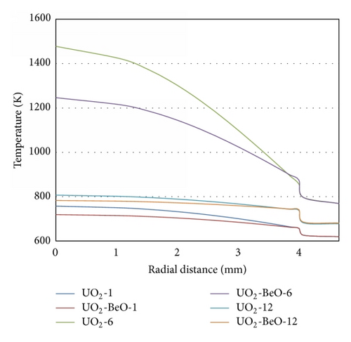
Radial temperature profiles (temperature as a function of radial distance) at three nodes (node 1, node 6, and node 12) are shown for the cases, Case 2 and Case 2(a) in Figures 6 and 7. Since the linear heat rate has a cosine form, temperatures at the lower most and upper most nodes are not too high. From these graphs, it can be clearly seen that the effect of BeO addition to the fuel causes a decrease in the temperatures attained. The drop in temperature with BeO addition is higher as the axial height of the nodes is increased till about the mid height where temperature hits maximum (nodes 6-7). Reason for this is that the linear heat rate peaks at the mid height of the rod.
As far as the MT-1 case is concerned, since this is not a steady state case, the radial temperature distribution is not the same at all instants. The cladding temperatures at different time instants are shown in the Figure 8.
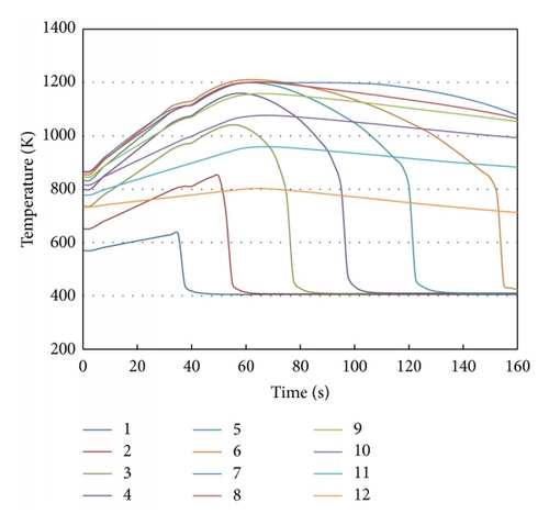
With data from the graph above, the radial temperature profile at the time instant where maximum transfer of heat occurs is obtained. For example, for node 1, it is at the 40th second and around at 60 seconds for the second node.
Figure 9 shows the comparison of the radial profiles for UO2 and UO2-BeO fuel for MT-1 case.
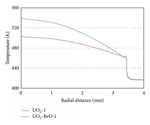
We find that the reduction in temperature is not significant for this case. Also, a steep drop in temperature occurs in the gas gap. This occurs because of greater quantities of gases due to rod burst.
4.2. Cladding Strain
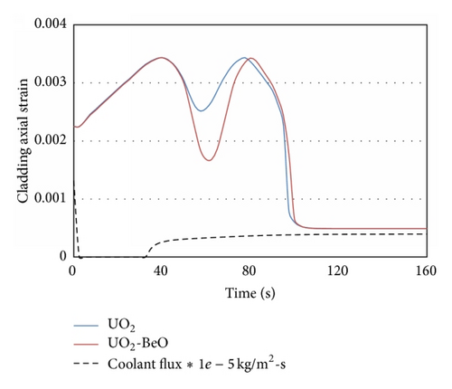
Cladding axial strains do not vary in case of steady state. In these cases (Case 1, Case 2, and Case 2(a)), cladding remains intact. However, in the case of MT-1, the fuel rod ruptures and significant reductions in cladding strains were observed. Examples of cladding axial strains at two nodes (fuel rod locations) are shown as a function of time in Figures 10 and 11. There is sharp drop in strain for UO2 fuel case at 30 seconds which corresponds to the cold water injection.
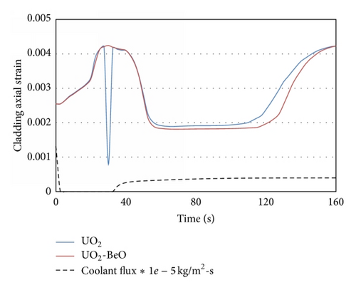
The difference in cladding strains upon using BeO fuel can clearly be observed in these plots. While looking at these plots, it can be seen that the maximum value of cladding strain occurs at different time instants for different nodes. The time instants for different nodes are mentioned in Table 3.
| Node | Time at which maximum strain was observed (s) |
|---|---|
| 4 | 62.5 |
| 5 | 80 |
| 6 | 92.5 |
| 7 | 127.5 |
| 8 | 97.5 |
| 9 | 67.5 |
The cladding strain depends on axial power profile and cooling due to reflood. Node 7 has the highest heat input and, given that the coolant (reflood water) is fed into the core at the bottom, it takes longer time for the coolant to reach node 7. The combined effect of both these factors could be a reason for node 7 taking maximum time for maximum cladding strain to occur.
To conclude, it is observed that BeO addition fuel causes a significant drop in the cladding strain values when failure of the fuel rod occurs.
4.3. Gas Gap Pressure
Table 4 summarizes the results of gas gap pressure for MT-1 case. With the use of BeO fuel, a small drop in gas gap pressures is observed from FRAPTRAN simulations, for the cases in which the core remained intact.
| Case | Gas gap pressure (MPa) | Reduction % | |
|---|---|---|---|
| UO2 fuel | UO2-BeO fuel | ||
| Case 1 | 4.2242 | 4.0742 | 3.55% |
| Case 2 | 4.3528 | 4.196 | 3.60% |
| Case 2(a) | 2.8204 | 2.8204 | — |
Even though rupture did not occur in Case 2(a), there was no significant change in the gas gap pressure as the temperatures reach very high values and cladding strains are also excessive in this case. The reduction in gas pressures in the MT-1 case is also almost nil due to a gas breach. It can be concluded, hence, that the gas gap pressure is reduced when the cladding remains intact, that is, when there is enough cooling so that cladding strains are not too large.
4.4. Energy in Fuel Rod
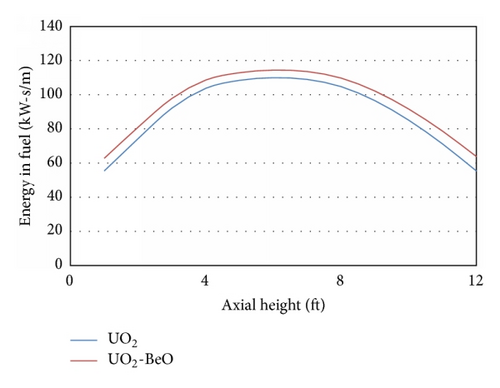
Energy in the fuel was compared between UO2 fuel and UO2-BeO fuel. It was found that there is a drop in this value and the percentage reduction is highest at the mid height of the rod where peaking of cosine curve occurs. Plot of this parameter as a function of axial height is shown in the Figure 12. It can thus be concluded that there is a small drop in energy in fuel upon using BeO fuel and the extent of drop depends on the temperature/heat input at that particular node. A similar trend was observed for the other cases also.
5. Conclusions
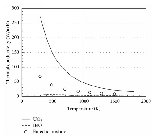
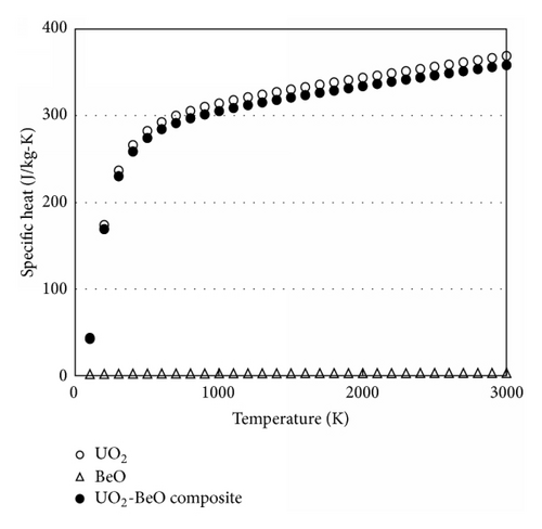
The aim of this study, to model and study the performance of a composite fuel UO2-BeO using a fuel performance code, FRAPTRAN was accomplished. Subroutines that calculate thermal conductivity, specific heat, and specific enthalpy of the fuel were modified for the new fuel. For thermal conductivity, an expression similar to that used for calculation of thermal conductivity of the oxide fuel was used. This expression agreed with thermal modeling results which were in accordance with experimental results. For specific heat and specific enthalpy, mass weighting technique was used. Using FRAPTRAN, performance of this composite was studied under a series of conditions ranging from normal operation to a rupture scenario. For this purpose, four different cases were run with input decks created accordingly. Key conclusions include the following.
A significant reduction in fuel centerline temperatures was observed in the cases that ran for normal operation scenario, as reported in the literature by Latta et al. [8]. This was, however, not so significant under a rupture scenario. Gas gap pressure was found to reduce with the addition of BeO to UO2. A reduction of about 3.6% in values of gap pressure was observed in the cases of normal operation.
Energy in fuel was also found to reduce with addition of BeO to nuclear fuel. It was observed that reduction in energy in fuel was highest where the heat input reached its maximum value.
Another important parameter, cladding axial strain, was found to reduce with the use of BeO. This also, like energy in fuel, depends on the heat input given and also on the cooling present.
With these results obtained, it can be concluded that addition of BeO to nuclear fuel gives rise to other advantages like reduction in gas gap pressure, energy in fuel, and cladding strain under conditions of failure or rupture apart from the reduction in fuel centerline temperature and that addition of BeO to nuclear fuel will turn out to be advantageous. It should be noted that the MT-1 case test was carried out with zero burnup fuel. And the properties used here for UO2-BeO fuel are for zero burnup fuel. Hence, it can be said that the present results apply to the fresh fuel scenario.
Conflict of Interests
The authors declare that there is no conflict of interests regarding the publication of this paper.
Acknowledgment
This work was supported by IBC Advanced Alloys Corp.


