A Driver Modeling Based on the Preview-Follower Theory and the Jerky Dynamics
Abstract
Based on the preview optimal simple artificial neural network driver model (POSANN), a new driver model, considering jerky dynamics and the tracing error between the real track and the planned path, is established. In this paper, the modeling for the driver-vehicle system is firstly described, and the relationship between weighting coefficients of driver model and system parameters is examined through test data. Secondly, the corresponding road test results are presented in order to verify the vehicle model and obtain the information on drive model and vehicle parameters. Finally, the simulations are carried out via CarSim. Simulation results indicate that the jerky dynamics need to be considered and the proposed new driver model can achieve a better path-following performance compared with the POSANN driver model.
1. Introduction
Although the chassis control systems of a vehicle can improve vehicle dynamics performances, enhance active safety, and reduce driver load, they bring more challenges for the evaluation of vehicle performance, especially for the evaluation of handling and stability in terms of subjective sense [1, 2]. Previous studies [3, 4] reveal that the driver-vehicle-road closed-loop system works effectively when investigating the performances of vehicle handling and stability. In order to evaluate the handling quality of a vehicle and avoid potential risk in actual tests, the study on driver modeling is essential. This research field has drawn significant attention and several typical models have been carried out by many researchers in an early time. In 1953, Kondo [5] started with driver modeling in Japan. His research is based on the 2-wheel vehicle model on a straight line, running at a constant speed with side wind disturbances. In addition, McRuer and Jex [6] extended pilot models to road driver models by considering the factors of reaction time and inertial delay and a compensation driver model was presented. However, the preview characteristics of the driver were not taken into consideration in the studies. Macadam [7] established a driver model by using optimal preview closed-loop control in 1980. Moreover, the Preview-Follower theory [8] was proposed for the purpose of modeling the driver’s path-following behaviors. The driver’s behaviors were assumed based on the path-following theory in which the driver’s operation always aims at minimizing the errors between the desired and actual vehicle trajectory [9]. With the development of intelligence technology, several artificial neural network driver models were proposed in order to accurately imitate human driving behaviors. For instance, Fujioka et al. [10] presented a NN driver model, in which the steering angle was mapped as a function of lateral deviation and heading angle. The model was trained by a human driver in a simulator environment. Neusser et al. [11] also proposed a neurocontroller for lateral vehicle guidance. This driver model was trained with measured human-driving data. In addition, Macadam and Johnson [12] constructed a two-layer neural network to represent driver steering behaviors. Sampled data collected by the sensors of an on-road car was employed to train the network. Guo et al. [13] proposed a preview optimal artificial neural network (ANN) driver model, whose training sample was the ideal following path instead of experimental data. The global optimization of the closed-loop system was carried out in the training process of the network through the Genetic Algorithm. Further research showed that the weight factors of this artificial neural network could be calculated analytically through the Error Elimination Algorithm [14]. For the sake of simulating driver behaviors under some severe or critical scenarios, Edelmann et al. [15] presented a driver model for higher lateral accelerations. The driver model was able to perform a good tracking behavior even at higher lateral accelerations. Tracking accuracy was further enhanced by incorporating information on the change of curvature and the local curvature of vehicle motion in the prediction of anticipated vehicle positions. The above-mentioned models were established based on the driver’s visual sensory inputs; kinesthetic (steering torque) or vestibular (lateral acceleration, yaw rate, and slip angle) sensory was not taken into account. Recently, some driver models were proposed in [16–18]; those models integrate both anticipatory and compensatory visual strategies and take into account both visual perception and kinesthetic perception. Little amount of the literature gives information on how vestibular information is used.
Many driver models have been established based on many kinds of modern control theories and methods. Unlike acceleration, velocity, and displacement of vehicle, the time derivative of acceleration (TDoA) of vehicle motion, which is used to show the vestibular information, has not been extensively studied in those studies. The TDoA, also referred to in the literature as jerk, is one of the parameters considered in vibration control [19] and comfort evaluation [20, 21]. It is a physical property that is felt by humans when a sudden change of motion occurs. Consequently, it is closely monitored for discomfort caused to a passenger in a vehicle. As a sudden change of motion occurs, the vehicle might drop into the boundary area of stability, and the tire forces are prone to sudden change. The driver response can be made according to the steering torque feedback and the jerk dynamics on the vehicle response to lateral force change. Thus, the optimal preview control driver model cannot achieve accurate vehicle performance, especially when the tires are in the sudden change conditions.
Hence, it is essential to consider the TDoA of vehicle motion in the preview-follower driver model. Based on the preview-follower driver modeling approach and ANN, a modified driver model considering the jerky dynamics is investigated. The drivers’ behaviors are described with the parameters of preview and jerk characteristic. The steering angle is obtained according to the error between the real track and the planned path and modified by the jerky dynamics under lateral force mutation. This paper is organized as follows. A modified driver model is presented in Section 1. Internal vehicle model is built and simplified in Section 2. The parameters of driver and vehicle characteristics are analyzed and calculated according to the driving conditions in Section 3, where road tests are used to verify vehicle model and calculate the closed-loop system parameters. Numerical simulations are employed to verify the proposed driver model in Section 4. Conclusions are given in Section 7.
2. Modeling of Driver-Vehicle System
Many driver models have been established to simulate the characteristics of driving behaviors on the desired trajectory. On the basis of the previous researches, the paper explores the driver model based on the combination of the preview-follower theory and the jerky dynamics.
2.1. Preview-Follower Theory
- (1)
Since the drivers operation is a low frequency process under usual driving, the transfer function of the closed-loop system should always be 1 at low frequency range. That is, P(s) · F(s) ≈ 1. The theory is realized by a cascade system, which is composed of a preview and a follower. P(s) and F(s) denote the preview and follower transfer functions, respectively.
- (2)
Figure 1 shows the diagram of the preview-follower’s structure, where y denotes the vehicle’s actual lateral position and f and fe denote the vehicle lateral position on the absolute and vehicle coordinate system, respectively [8].

2.2. Preview Optimal Simple Artificial Neural Network Driver Model
Generally, the behaviors of a qualified and excellent driver fit with the Preview-Follower theory. According to this knowledge, the preview optimal simple artificial neural network (POSANN) driver model is built in Figure 2.
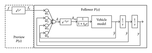
In the preview module P(s), the driver can acquire the effective road information fe from target course f through preview process, whose transfer function is , in which tp indicates the driver preview time for path following. The input f represents the function of the lateral displacement of the target course, and the output fe indicates the lateral displacement of the target course at look-ahead point.
In the follower module F(s), the driver uses the motion information of the vehicle to decide on the optimal steering wheel angle δ. However, since there are response delays of both human and vehicle, the real steering wheel angle of vehicle should be δsw. w1 ~ w4 are the ANN weight coefficients of fe, lateral displacement y, lateral speed , and lateral acceleration , respectively. Here, human factors are taken into account, which are expressed by the reaction delay of the driver with the transfer function . In this transfer function, td is the lag of the driver’s neural reaction system. 1/(1 + ths) reflects the inertial delay of the steering system.
2.3. A Modified ANN Driver Model with Jerky Dynamics

If there are more differences between ayi and aym that the driver can feel, more corrections of the steering wheel angle will be made.
3. Internal Vehicle Model
Different vehicles lead to different second order systems. Based on step test data, the parameters (T1, T2, Ty1, and Ty2) of the second order system were identified by LSM (Least-Square Method) in this paper.
4. Parameters of Closed-Loop System
In this section, the parameters of closed-loop system are calculated with regard to the test data and road condition. Those parameters represent common behaviors of the driver and vehicle, including the preview time tp, neural reaction time td, and inertial delay th of steering system. In a real world application, most of those parameters are uncertain factors. The H∞ control and robust control have been also paid considerable attention to eliminate the impact of uncertainty [26–28], According to some particular parameters values, we can obtain the weighting parameters of the driver model by the Error Elimination Algorithm. The meaning and features of each parameter will be described in detail in the following part.
4.1. Preview Time tp
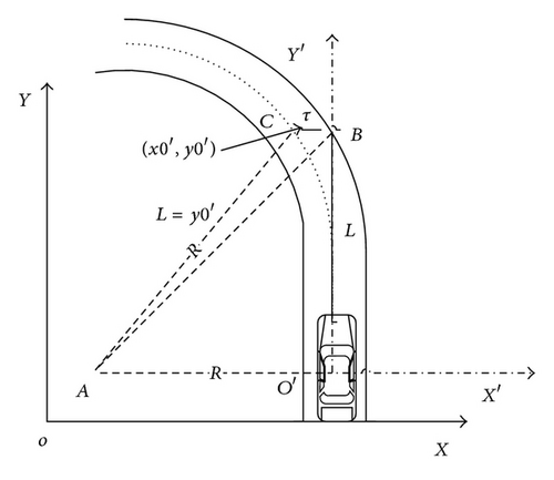
Through the above analysis, it has been seen that τ has an influence on the key parameter tp. The value of τ can be measured through the road test as shown in Figure 4. tp can be estimated based on (15).
4.2. Reaction Time td
4.3. Inertial Delay th
4.4. Weight Parameters of Driver Model
5. Test Identification and Model Verification
In order to obtain the model parameters, a lot of experiments have been carried out using a small car as test vehicle. Furthermore, the vehicle model will be verified to ensure the effectiveness of vehicle model in simulations.
5.1. Vehicle Model Verification
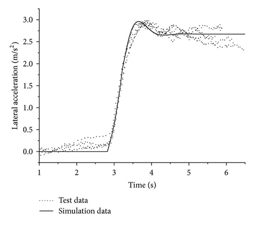
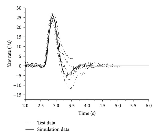
The simulations are carried out in CarSim, in which complex vehicle model can be built up to operate in nonlinear region. The vehicle model is verified by comparing the simulations and test results. Two typical tests including step input and pulse input of steering wheel angle are presented and shown in Figures 7 and 8, respectively. From the figures it can be seen that the simulation results fit the test results well, indicating that the vehicle model can be used in simulation with sufficient accuracy.
5.2. Calculation of Model Parameters
(1) The Offset τ. Based on Section 4.1, the road tests are carried out to calculate the offset τ. Typical driver A is selected for road tests. Driver A is skilled and professional with high driving proficiency. In the tests, the initial positions of the steering wheel change and speed had been recorded when the driver saw the first bend and intended to enter the bend. The offset τ was calculated and the average of results is 0.843 m.
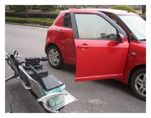
(2) Simple Reaction Time T. In order to get actual simple reaction time T of drivers, the tests are carried out in a proving ground, in which the environmental distraction can be eliminated. The test method is to record the procedure of simple stimuli-human reaction-execution behavior using a high-speed digital camera. The test system is composed of a test car, a camera, a signal lamp, and a data collector, as shown in Figure 9. The camera is Redlake Y3 high-speed digital camera, which can provide very high sample frequency up to 2000 fps. Eight men and one woman are selected to complete this test. During the test, each subject sits in the stationary vehicle and observes the signal light. Once the signal lamp is lighted, the subject should turn the steering wheel immediately. Meanwhile, the camera records the whole process of the steering wheel operation. The time difference from the time when the signal lamp is lighted to the time when the subject starts to turn the steering wheel is the simple reaction time T. Each subject should complete the test 10 times, and the average value of these data is taken as the final result. All test results are presented in Table 1.
| Test number | Subjects | ||||||||
|---|---|---|---|---|---|---|---|---|---|
| 1 | 2 | 3 | 4 | 5 | 6 | 7 | 8 | 9 | |
| 1 | 257 | 439 | 279 | 247 | 280 | 450 | 408 | 267 | 244 |
| 2 | 256 | 466 | 271 | 255 | 271 | 269 | — | 245 | 237 |
| 3 | — | 293 | 249 | 242 | 265 | 239 | 284 | 225 | 293 |
| 4 | 263 | 257 | 242 | 260 | 263 | 258 | 381 | 219 | 332 |
| 5 | 273 | 281 | 253 | 279 | 338 | 240 | 341 | 211 | 268 |
| 6 | 314 | 266 | 295 | 276 | 277 | 273 | — | 280 | 273 |
| 7 | 267 | 315 | 241 | 253 | 338 | 236 | 373 | 260 | 265 |
| 8 | 284 | 313 | 293 | 228 | 377 | 245 | 306 | 198 | 260 |
| 9 | — | 248 | 285 | 281 | 256 | 234 | 296 | 186 | 280 |
| 10 | 314 | 244 | 266 | 274 | 286 | 241 | 353 | 290 | 258 |
| Average T | 276 | 302 | 267 | 261 | 290 | 250 | 341 | 238 | 271 |
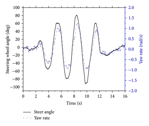
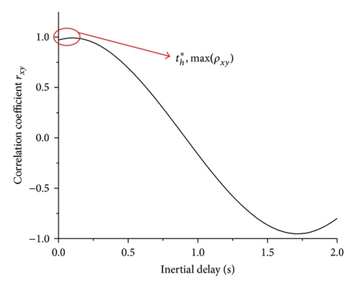
(3) Inertial Delay th. According to Figure 5, (19), and (20), the delay time of the steering system is determined by the maximum value of ρxy. When the value of the correlation coefficient becomes the max value, ρxy = 0.98727, the value of the corresponding horizontal axis is inertial delay, th = 0.12 s.
6. Simulation Results and Analysis
In order to examine the influence of driver model with the jerky dynamics, the comparisons are made in several cases by simulations for the driver models with/without the compensator using the identified vehicle parameter. Here, taking the skilled driver A as an example, simulation tests are conducted in CarSim. Two emergency cases and results are described as follows.
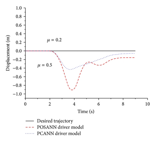
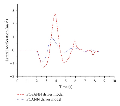
Case 1. The vehicle runs at the speed of 40 km/h on a μ-split road without ABS, which has two different friction coefficients on the left/right sides of the road center line, that is, 0.2 and 0.5. After 2 s, braking is exerted till the vehicle stops completely. The lateral displacement and acceleration of vehicle are shown in Figures 10 and 11, respectively. POSANN driver model cannot achieve accurate path following, while the PCANN driver model produces better path-following performance, considering the y-coordinate error and the lateral acceleration error. The maximum position error is 0.936 m with the POSANN driver model. Meanwhile, the maximum error obtained with the PCANN driver model is 0.435 m, which is 46.5% of that of POSANN driver model. The maximum lateral acceleration error with the POSANN driver model is 2.83 m/s2. Meanwhile, the corresponding error, 32.4% of that of the POASNN driver model, is 0.918 m/s2 with the POSANN driver model. Obviously, it can be seen that the PCANN driver model of the driver A can reduce vehicle lateral responses effectively and make the vehicle recovering to the stable condition much more quickly than POSANN driver model.
Case 2. In order to simulate extreme working conditions, the double-lane change is carried out in CarSim, supposing that the vehicle runs at the speed of 80 km/h into the slippery road of μ = 0.2, and the other conditions are under ideal conditions. The responses of lateral displacement and acceleration are shown in Figures 12 and 13, respectively. From these two figures, it can be obtained that the vehicle with the PCANN driver model has better performance of the lateral acceleration and the lateral displacement than that the POSANN driver model. The sway of the vehicle with the PCANN driver model is smaller than that the POSANN driver model. It is obvious that the PCANN driver model of driver A can adapt to environmental changes more rapidly.
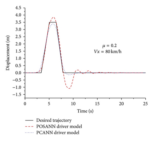
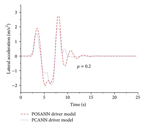
The above results in two emergency cases show that compared with the POSANN driver model, the proposed PCANN driver model can adapt to the changes of road condition more quickly, implying that the driving compensation is very necessary especially in emergency cases for the driver. The compensator will exhibit more potential benefits when the road is worse.
7. Conclusion
A new POSANN-based driver model with compensator controller using the jerky dynamics is investigated. The compensator controller is built using linearized models of the nonlinear vehicle dynamics and vehicle current states to generate a steering corrected value for the POSANN driver model. The key model parameters reflecting the driving behaviors, such as preview time and reaction time, are calculated according to the test data which can vary with changes under operating conditions. The inertial delay of the steering system is obtained by the cross-correlation method, which is applied to eliminate random fluctuation of experimental data. Simulation results demonstrated that the proposed driver model can achieve better path-following performance than the POSANN driver model under critical maneuvering conditions. Furthermore, the driver model can be used effectively for representing driver steering control behaviors to some extent. Consequently, the proposed driver model presented in this study can be used in a closed-loop simulation and in the development of the vehicle’s intelligent safety system.
Acknowledgments
The authors acknowledge the support of the research team of test technology on the active safety of automobile (2012-CX-04). The authors greatly appreciate the support of the National Natural Science Foundation of China (no. 51375299).


