A p-Strategy with a Local Time-Stepping Method in a Discontinuous Galerkin Approach to Solve Electromagnetic Problems
Abstract
We present a local spatial approximation or p-strategy Discontinuous Galerkin method to solve the time-domain Maxwell equations. First, the Discontinuous Galerkin method with a local time-stepping strategy is recalled. Next, in order to increase the efficiency of the method, a local spatial approximation strategy is introduced and studied. While preserving accuracy and by using different spatial approximation orders for each cell, this strategy is very efficient to reduce the computational time and the required memory in numerical simulations using very distorted meshes. Several numerical examples are given to show the interest and the capacity of such method.
1. Introduction
In early works, we have proposed an efficient new Discontinuous Galerkin (DG) method to solve the Maxwell equations in time domain [1]. However, in order to treat industrial problems, we have generally to cope with a very distorted meshes with a large difference between the sizes of the cells. In the DG simulations, the spatial approximation order taken into account is obtained by considering the size of the largest cell and the largest frequency in the spectrum of the excitation source. Consequently, our method suffers from a sampling that is too high for the smallest cells in the mesh and from a time step that is very small to ensure stability. To improve the choice of the time step, we have proposed a local time-stepping strategy in the method [2] which allows reduction of the computational time. Nevertheless, the spatial order of approximation remains the same for all the cells, and for a given source, some cells are too sampled and lead to a local time step on these cells still too small. To avoid this problem, a method with local order on the cells can be used [3]. Some works have been already realized for Maxwell′s equation on this subject, with classical upwind DG formulation and ADER strategy [4]. In this paper, we present, for a particular DG method well adapted to the Maxwell equations, a strategy to mix spatial orders of approximation in each cell on the whole mesh. This strategy allows decreasing the order of the small cells and then increasing the CFL condition for these cells and consequently their local time-step. Indeed, it has been shown, for the DG method used, that the CFL condition decreases when the spatial order of approximation increases [5].
In the first part of this paper, we recall the mathematical formulation of the DG schema studied and the local time-stepping strategy used. In the second part, the formulation of a local spatial approximation order or mixed-spatial order strategy is given and introduced in the presented DG scheme. A mathematical study for the stability of the resulting numerical scheme is also shown. Finally, in the third part, a numerical study by using the mixed-spatial order strategy with the local time-stepping strategy is done.
2. Mathematical Formulation
In this section, we recall first the formulation of the DG method taken into account in the study of our mixed-spatial order strategy. Next, we present the local time-stepping strategy used to improve the DG performances.
2.1. Discontinuous Galerkin Method
Let Ω be a bounded open subset of ℝ3 whose boundary is ∂Ω, and let n denote the unit outward normal to Ω. Let ɛ(x), μ(x), and σ(x) denote, respectively, the permittivity, the permeability, and the conductivity of the medium.
We consider the problem described by the Maxwell equations.
Usually, for DG methods, E and H fields are approximated by polynomials on each cell. In our case, we approximate by polynomials the fields and on . It is not a strange choice since the Jacobian matrix is the essential ingredient to build a conform H-curl approximation [7, 8]. As we will see later, this will imply interesting properties for memory storage.
Finally, we consider the following semidiscrete DG method.
- (i)
for all ,
- (ii)
for all .
For the time discretization, as for the FDTD method [9, 10], we use a Leap-Frog numerical scheme where the electric fields are evaluated at the time nΔt and the magnetic fields at the time (n + 1/2)Δt, with Δt defining the time step and n the current iteration in time.
In the sequel, we say the DG method is a Qr approximation when we choose a spatial approximation order of r.
- (i)
for mass matrices, ((M) pl denotes the (p, l) component of the matrix M):
() - (ii)
for stiffness matrices, ((M) l denotes the component l of vector M):
() - (iii)
for jump matrices
()
Then, the important advantage of this DG method is to give, regardless of the space approximation order, a very low memory storage and a small cost of computation to evaluate the matrices of the numerical scheme. This allows us to use meshes with a small number of cells and a high order spatial approximation to obtain very accurate solutions. Consequently, to obtain an accurate solution, the memory and CPU costs needed to solve a problem with this approach are lower than those for some other methods, as, for example, FDTD, based on a spatial approximation of order 2 and using more refined meshes. In fact, high order spatial approximation reduces the dispersive and dissipative errors of the scheme and improve the accuracy of the solution. The use of non-cubic cells, like for the FDTD method, in the meshes in the method permits also to evaluate correctly the fields near the structures. Therefore the proposed method is well adapted not only to Electromagnetic coupling problems for which it is essential to know this kind of values, but also to cavity problems where the dispersive and dissipative errors may not be neglected.
2.2. Local Time-Stepping Method
The previous DG numerical scheme studied is based for the time domain on an explicit Leap-Frog discretization [9]. Nevertheless, when dealing with unstructured meshes, we can obtain significant cell size disparities and, to ensure stability, the global time step is constrained by the smallest cell of the mesh. This implies an important increase of the computational time. To avoid this problem, a local time-stepping strategy has been proposed for the Leap-Frog time discretization [2]. This method is based on a decomposition of the cells of the mesh in a set of N classes of cells where each class i has a time step given by 3N−iΔtmin r, with Δtmin defining the smallest time step on all the classes.
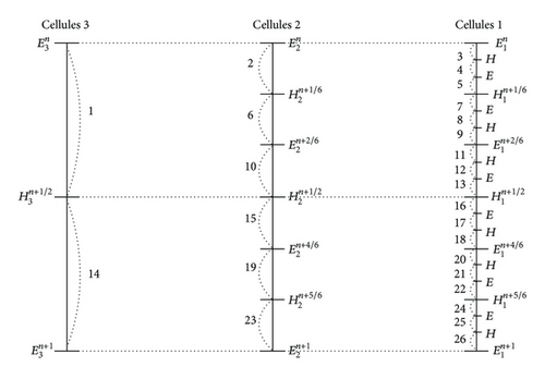
For example, when the problem has 3 classes, the different operations that proceed in a step of the local time-stepping Leap-Frog method are given in Figure 1. We consider that the time step for the method is given by the largest value on all the classes.
This local time-stepping strategy can be easily implemented as a recursive process.
3. Mixed-Spatial Order Approximation Strategy
- (i)
define the smallest wavelength λmin by considering the spectrum of the source;
- (ii)
define an equivalent geometric length h on each cell;
- (iii)
allocate a spatial order r = (h/λmin )n on each cell by considering h, λmin , and a given n.
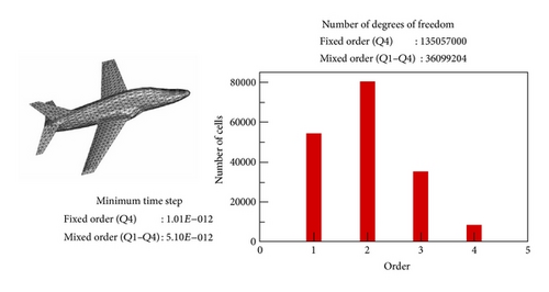
The difficulty in this strategy is to determine a value of h for each cell equivalent to its size. Several possibilities have been tried and the most interesting is a value which corresponds to the largest diagonal length of the element. By considering this value, we do not overestimate or underestimate the spatial discretization in any direction of the element. The example given in Figure 2 shows the gain that we can expect by applying a mixed-spatial order strategy. In particular, we can see that the time step of the method using mixed-spatial order is higher than that without using it. This implies a smaller number of time iterations to describe a given range in time and then a gain in computational time. We note also a decrease in the number of degrees of freedom in the problem which leads to a lower required memory. However to confirm the interest of this approach, it is also important to compare the accuracy of the solutions obtained. This point has been developed in Section 3.3.
3.1. Jump Matrix
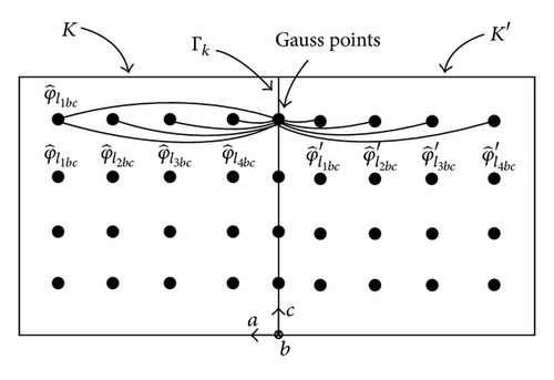
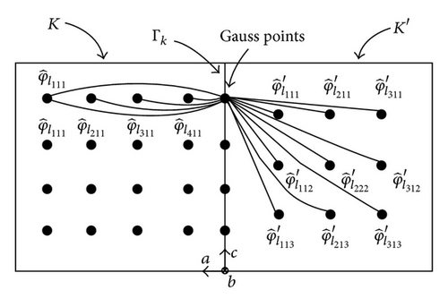
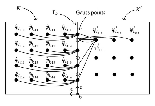
By using a Gauss quadrature formula of order equal to the largest spatial approximation order of K and K′ to evaluate the integrals, our choice of basis functions leads to having only few nonnull interactions. Figure 3 in 2D case, gives the nonnull contributions of the different basis functions considering a same spatial order approximation for both adjacent elements to the face. In this case, for each point of quadrature, only a line of basis functions is used (this is also true in 3D). This is different when the adjacent cells to the considered face have not the same spatial order approximation. In this case, to compute the “crossed-jump” terms, we need to use all the basis functions for each point of quadrature (2D case as 3D case). Figures 4 and 5 show examples of the different interactions taken into account to compute these terms. We show in these figures that the calculation processes are not symmetric.
3.2. Stability
In the case of the mixed-spatial order strategy proposed in this paper, this result still holds.
Proposition 1. For the multiorder nondissipative scheme, the discrete quantity is conserved during the discrete time:
Proof. This proof is classical and does not raise any difficulty. This is why we give only the key points of the proof. First, by taking the test functions and in the nondissipative fully discrete scheme, one can easily obtain [5]
So, if one takes for T1± the Gauss quadrature rule of order r± and for T2, T3 the same quadrature rule for G+ and G− (not necessarily the one corresponding to the highest spatial order), one obtains T = 0.
So, one can give the stability result [1].
Theorem 2. Let be the 3(rK + 1) 3 × 3(rK + 1) 3 matrices defined by the following: for all l, l′ ∈ {1,2, 3} and for all I = (i, j, k), I′ = (i′, j′, k′)∈{1, …, rK + 1} 3
Proof. The proof of the theorem is the same as the one given in the paper [1]. We must only take into account a different spatial order for each cell. However this does not imply any modification in the proof.
Remark 3. In the case of the dissipative scheme, the stability can be also proved by using a modified discrete energy analysis as defined in [2].
3.3. Numerical Results
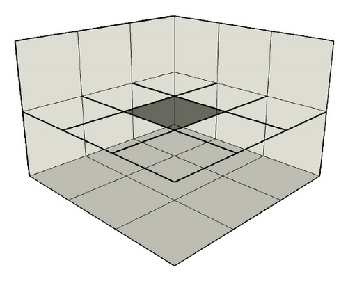
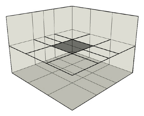
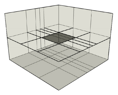
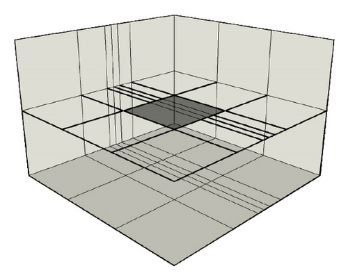
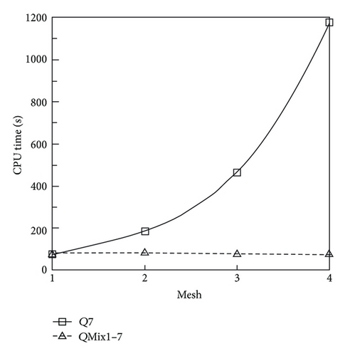
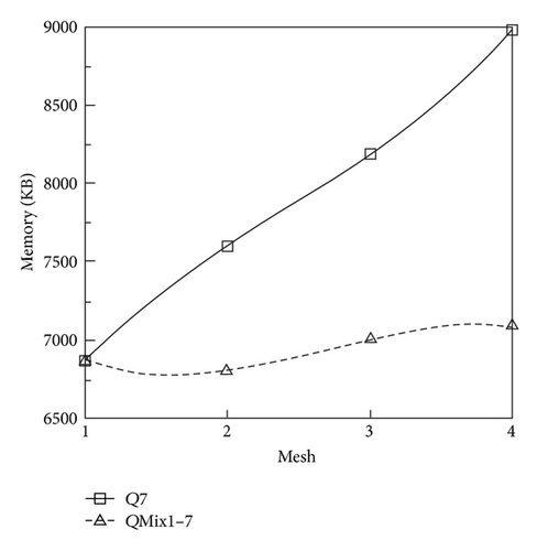
In this section, we present three examples to quantify the advantages of the proposed mixed-spatial solution strategy. The first example consists in evaluating the field scattered by a 1m × 1m perfectly metallic surface illuminated with a plane wave. This evaluation has been done for different meshes where the ratio between the smallest and the largest cell is progressively increased in order to generate several spatial approximation orders. Figures 6, 7, 8, and 9 show partial views of the meshes, where for the same accuracy of the solution we compare the CPU-time and the memory storage. The initial mesh (Mesh1) consists in an uniform cartesian mesh of the computational domain. The other meshes are obtained from the initial mesh by recursively cutting one cell in two (see Figures 6, 7, 8, and 9). In this example, by considering the spectrum of the source and the largest size of the cell, our discretization criterion (see Section 3) leads to a maximal spatial order r = 7. So, we obtain a Q7 approximation for our meshes. Figures 10 and 11 show the CPU-time and the memory storage necessary for the DG method used with and without the mixed-spatial order strategy. We observe an important gain in CPU-time and in memory storage by using the mixed-spatial order approach. In particular we can note that our strategy implies a CPU time and a memory storage which are almost mesh independent.
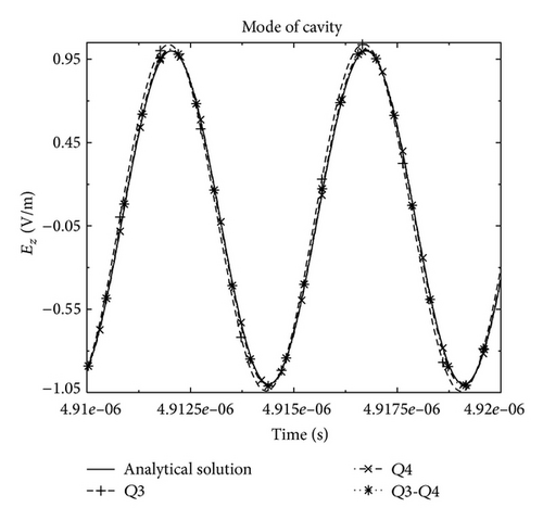
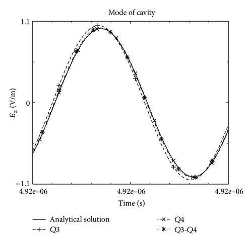
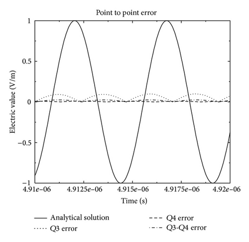
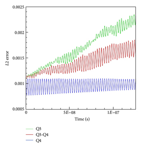
In this example, we evaluate the field at the center of the cavity for a given nonstructured mesh and we compare the solutions given by the DG method using or not the mixed-spatial order strategy. For our mixed-spatial order strategy, we obtain two orders (3 and 4) which are assigned in the mesh as shown in Figure 12.
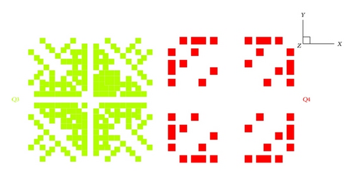
Figure 13 shows the analytical solution and the solutions obtained by the Q3, Q4, and the mixed Q3-Q4 DG approximations. We can see that the Q3-Q4 DG approximation leads to the same accurate solution of the Q4 DG method but its numerical costs are far from smaller (see Table 1). Finally, we show in Figure 14 that the Q3 solution is not sufficiently accurate whereas the mixed Q3-Q4 approximation gives the best compromise between CPU-time, memory storage, and accuracy.
| Order | Q3 | Mixed Q3-Q4 | Q4 |
|---|---|---|---|
| Ratio | 100% | 87.5%–12.5% | 100% |
| CPU time (s) | 25009 | 44217 | 70710 |
| Memory storage (MB) | 23 | 25 | 35 |
| DOF | 294912 | 330048 | 576000 |
| Time step | 7.74 · 10−12 | 7.74 · 10−12 | 5.17 · 10−12 |
In the last example we propose to evaluate the field scattered by an aircraft illuminated with a plane wave, by using the local time-stepping strategy given in Section 2.2, jointly with the mixed-spatial order strategy.
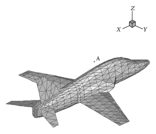
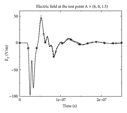
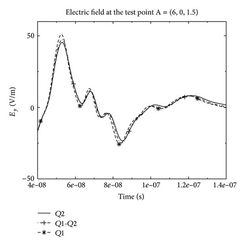
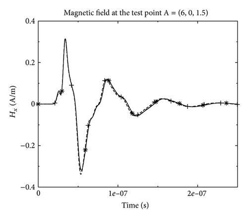
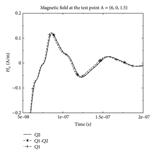
By considering the mesh (see Figure 15) and the spectrum of the source, the maximal order detected by our static adaptive strategy is equal to 2 in order to obtain 10 points per wavelength for the spatial discretization. So, theoretically, one must use a Q2 approximation to ensure an accurate computed solution if we consider only one spatial order for the DG method. However, due to the difference of the cells sizes in the mesh, the Q1 spatial approximation could be sufficient in some parts of the mesh. Then by using a mixed Q1-Q2 spatial order approximation, we obtain for this example an important gain in CPU-time (factor 7) and in memory storage (see Table 2). Figures 16 and 17 show the electric and magnetic fields at the test-point A (see Figure 15) obtained by Q1, Q2, and Q1-Q2 DG approximation for the same mesh. We can see that the solutions obtained by the mixed-spatial order is similar to the Q2 DG approximation, with a best cost in CPU-time and memory storage (see Table 2).
| Order | Q1 | Q1-Q2 | Q2 |
|---|---|---|---|
| Ratio | 100% | 20%–80% | 100% |
| CPU time (s) | 16478 | 58445 | 76229 |
| Memory storage (MB) | 673 | 1208 | 1316 |
| DOF | 5150208 | 14918982 | 17381952 |
| Minimal time step | 3.15 · 10−12 | 2.18 · 10−12 | 1.53 · 10−12 |
| Maximal time step | 8.51 · 10−11 | 5.88 · 10−11 | 4.15 · 10−11 |
4. Conclusion
In this paper we presented a p-strategy with a local time-stepping strategy for a particular Discontinuous Galerkin method to solve Maxwell′s equations in time domain. We proposed a simple strategy based on the frequency spectrum of the source and on a characteristic size of the cells to evaluate the spatial approximation order to be applied on each cell of the mesh. We showed the validation and the advantages of this method on simple examples. The stability of the method has been also studied and a stability condition has been established. Finally, this method has been applied to study the electromagnetic fields scattered by a 3D object typical of aeronautic applications and give good results with a very interesting gain in CPU-time and memory storage. However, in the proposed strategy, the order is the same in all the directions of the elements and this can be a drawback for elements stretched in a particular direction. In this case, it may be more interesting to affect an order for each direction inside each element. This is one objective of our future works.
Acknowledgment
This work has been supported by the French Délégation Générale de l′Armement (DGA).


