Sizing and Simulation of PV-Wind Hybrid Power System
Abstract
A sizing procedure is developed for hybrid system with the aid of mathematical models for photovoltaic cell, wind turbine, and battery that are readily present in the literature. This sizing procedure can simulate the annual performance of different kinds of photovoltaic-wind hybrid power system structures for an identified set of renewable resources, which fulfills technical limitations with the lowest energy cost. The output of the program will display the performance of the system during the year, the total cost of the system, and the best size for the PV-generator, wind generator, and battery capacity. Security lightning application is selected, whereas system performance data and environmental operating conditions are measured and stored. This hybrid system, which includes a PV, wind turbine, inverter, and a battery, was installed to supply energy to 24 W lamps, considering that the renewable energy resources of this site where the system was installed were 1700 Wh/m2/day solar radiation and 3.43 m/s yearly average wind speed. Using the measured variables, the inverter and charge regulator efficiencies were calculated as 90% and 98%, respectively, and the overall system’s electrical efficiency is calculated as 72%. Life cycle costs per kWh are found to be $0.89 and LLP = 0.0428.
1. Introduction
Renewable energy resources like solar and wind offer clean and economically competitive alternatives to conventional power generation where high wind speed and high solar radiation are available. For meeting the energy demand, PV-wind hybrid power generating systems can be beneficial in enhancing the economic and environmental sustainability of renewable energy systems. Growing public concerns over global warming as an impending outcome of greenhouse gas emissions initiated by energy resources based on fossil fuels have encouraged to study cleaner energy options, like PV, biomass, wind, and micro hydro systems for several applications. The record of worldwide photovoltaic (PV) market installations extended up to 27.4 GW in 2011 [1]. On the other hand, the commercial wind turbine installations around the world have expanded to 240 GW by the end of 2011 [2].
Renewable resources such as solar and wind energy which change randomly are individually less reliable. However, in many regions, when solar and wind resources are combined for power generation, they complement each other by means of daily and seasonal variations. Combining these two renewable energy sources could make the system more reliable, and the system costs might slightly decrease depending on the regional conditions. However, the energy system sizing procedure and operation control strategies are getting more complex due to the nonlinear components’ physical characteristics.
Photovoltaic-wind hybrid power systems are categorized as extraordinary complex in sizing and optimization process, where renewable energy resources and storage components must be sized to match the given load profile and the estimated ease of use of solar radiation and wind speed. Many PV-wind hybrid systems are unique in design, whereas the complete dynamic testing of hybrid system takes very long time and also its cost is very high. In some way, whether necessary time and budget are provided for the dynamic tests, it is very hard to test all the situations that will be met during the life cycle of the hybrid system. It is clear that if the individual performance does not match with the expected simulation outcomes, it leads the user to uncertainty. Without exact high-level comparisons between real objective performance and projected computer simulations, it is very hard to focus on enlightening the performance of PV-wind hybrid system. A reliable technique for assessing the performance of a hybrid power system at a specific location is an essential prerequisite for boosting investment in hybrid power systems. Such a technique is also suitable for comparing the performance of two hybrid power systems, specific conditions at a certain location [3]. For this reason, software design and simulation tools are important aids.
Several economic viability and technical availability studies are carried out to assess choice of PV-wind hybrid power systems configurations that serve power to the load with the certain reliability criteria [4–11]. The number of PV panels, wind turbines, battery cells, load profiles and available renewable resources plays a significant role in sizing of PV-wind hybrid power system. Researchers and scientists mostly use deterministic and probabilistic methods to size and simulate the PV-wind hybrid power system. In deterministic method, time-series data such as wind speed, solar radiation, ambient temperature, load profile, and site geographic position like latitude, longitude, and altitude are assumed to be known. Resource data like wind speed, solar radiation, ambient temperature, and load profile are needed, at least hourly basis for whole year [12–15]. Also on the chronological order of the resource data is really important. Frequency of time-series resource data is defined according to the chosen simulation step time period. In probabilistic method, resource data and load profile are assumed as random variables, and these variables may not be in the chronological order. Probabilistic method tries to develop appropriate stochastic model for power generation and power consumption and then combines these two models to determine a hybrid system risk model. A group of researchers reported two sizing methods for autonomous PV-wind hybrid power systems. The first one assesses hybrid system performance using energy to load ratio which is based on the yearly average of monthly hybrid system energy outputs [16–19]. The second one realizes battery to load ratio using the worst monthly scenario [20–22]. The other probabilistic method is proposed by Yang et al. [23]. The authors proposed to use a typical meteorological year (TMY) to find out a precise assessment of energy output of a PV-wind hybrid power system. Tina and Gagliano [24] sized a PV-wind hybrid power system with probabilistic method that is based on convolution technique by probability density function. Deterministic and probabilistic sizing and simulation methods have their own advantages and disadvantages. Sizing procedure utilizing deterministic approach has severe computational efforts and it gives suboptimum solutions depending on the type of the used resource data, whereas stochastic procedures are simple and also they may use daily or monthly average resource data instead of time-series resource data.
In this paper, a hybrid system model that covers costing and system performance variables is identified. Decision variables, objective function, and constraints are determined for this model. Using simple iterative technique, sizing variable and performance variables are optimized according to the objective function under constraints.
2. Material and Method
2.1. Solar Evaluation Instruments and Measurements
The solar-wind meteorological station is located on the roof of the Solar Energy Institute Building in Ege University for determining the local potentials of both solar and wind energy [25]. This station consists of four modules, namely, sensors, data logger, electric power, and a tripod kit. Table 1 gives the specification of the equipment used for the solar radiation, wind speed and direction, ambient temperature, and relative humidity measurements. The station is fully operated with solar energy using 10 W PV module [26] with 12 V 12 Ah battery backup [27] and hereby the additional energy is not needed. The data gathering is made at an interval of ten minutes and the monthly average values are also logged. The meteorological station was installed in January 2005 and the measurements have been carried out since then.
| Module | Parts | Specification/description |
|---|---|---|
| Wind speed | Accuracy 0.5 m/s | |
| Wind direction | Precision 0.8 m/s | |
| Sensor | Pyronometer | 4.7 μV/W |
| Ambient temperature | −40 to 56°C, accuracy < 0.5°C | |
| Relative humidity | 12–100%, accuracy < 3% | |
| Signal input | 12 channels | |
| Data logger | Memory | 2 Mbytes |
| Computer connector | RS-232 | |
| Power | PV module | 15.1 V, 10 WPeak |
| Tripod | Stainless steel | For right setting the sensors |
2.2. PV-Wind Hybrid System
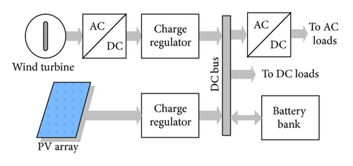
PV-wind hybrid energy system’s main components are shown in Figure 1. PV array and wind turbine generate energy for the load. Battery stores excess energy and supplies the load when the generated energy is not enough for the load. Battery charge controllers keep battery voltage within specific voltage window and thus, they prevent overdischarge or overcharge regimes. To protect the battery against overcharging, PV array and wind generator is disconnected from the system when the DC bus voltage increases above Vmax-off and when the current required by the load is less than the current generated by the PV array and wind generator. They are connected again when DC bus voltage decreases below Vmax-on. To protect the battery against excessive discharging, the load is disconnected when the DC bus voltage falls below Vmin-off and when the current required by the load is greater than the current generated by the PV array and wind generator. The load is switched on when DC bus voltage increases above Vmin-on. The inverter converts generated energy from DC to AC for an AC load.
2.3. PV Module Performance Model
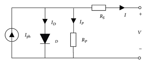
A PV module consists of a number of solar cells connected in series and parallel to obtain the desired voltage and current output levels. Each solar cell is basically a p-n diode. As sunlight strikes a solar cell, the incident energy is converted directly into electrical energy. Single-diode mathematic model is applicable to simulate silicon photovoltaic cells, which consists of a photocurrent source Iph, a nonlinear diode, and internal resistances RS and Rp, as shown in Figure 2. In the manufacturer’s datasheets, usually basic electrical characteristics of a PV module are given. We may obtain short-circuit current, open-circuit voltage, and the maximum power point (MPP) current and voltage values that are available in the datasheet. In addition, the manufacturer’s datasheet provides PV cell temperature coefficients referred to as current and voltage. Module current and voltage values depend on temperature and irradiance. The temperature coefficient of the cell referred to as voltage is negative and large. On the other hand, the temperature coefficient of current is positive and small. In some PV cell models, current variations with temperature can be neglected, and the voltage variations with temperature are defined for a PV module consisting of Nc cells connected in series [28].
2.4. Wind Turbine Performance Model
2.5. Battery Performance Model
2.6. Inverter, Charger, and Loads Performance Model
2.7. Costing Model of Hybrid System
The hybrid system operation costs are in general nonlinear and depend largely on the component size and type, and the way the system is operated. As they depend on future operations, they can only be estimated roughly [35].
3. Results and Discussion
3.1. Case Study
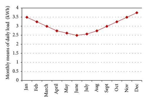
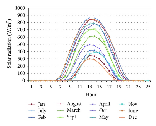
This section demonstrates the effectiveness of the proposed methodology by means of an implication of PV-wind hybrid system. The developed methodology is used to project a PV-wind hybrid power system for security lighting in the Solar Energy Institute Building. Inputs of the project are load profile, and hourly average of solar radiation, ambient temperature, and wind speed resource data for whole of the year. The load on the system is an experimental lighting of Solar Energy Institute. Load demand changes according to the period of the night. For the purposes of validating the model performance, the proposed algorithm is coded and simulated with MATLAB V 7.7 [37] that will also be employed as a software tool during optimization. The monthly means of daily average loads are shown in Figure 3. Daily resource data were calculated using monthly mean solar radiation and wind speed, and the results are shown in Figures 4 and 5, respectively.
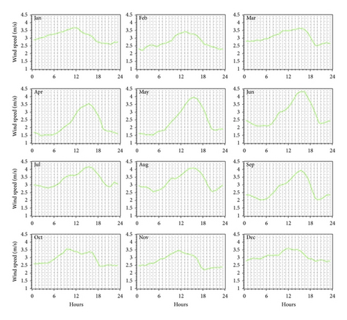
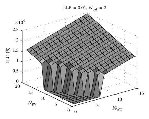
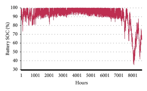
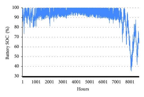
Using MATLAB code, the initial values of sizing variables referred to as hybrid system components and type of system components were defined and shown in Table 2. Equation (15) was optimized with respect to NBat, NPV, NWT, BCtype, and operation strategies to minimize the life cycle costs. Using simple iteration technique, sizing variables were defined and the results are shown in Figure 6. Because of the economical constraint and availability of wind turbine, NWT is set to 1 instead of 2, and then the system was reoptimized according to one wind turbine. And then the LLP value was revised to be 0.0738. Using defined sizing variables and operation strategies, the hybrid system model was simulated according to hourly weather data, and SOC is shown in Figure 7. Life cycle costs per kWh are calculated as $1.0076. The optimized hybrid system configuration is shown in Table 3.
| Variables | Symbol | Initial value or type |
|---|---|---|
| Number of series connected modules | NSM | 2 |
| DC bus voltage | VDC | 24 volts |
| Battery cell voltage | VBat-Cell | 2 volts |
| Number of series connected batteries | NSBatt | 12 |
| PV module type | PVtype | SM50 |
| Wind turbine type | WTtype | 3 blades, PMSG |
| Inverter type | INtype | True sine wave |
| Battery cell capacity | Qcell | 110 Ah |
| Wind turbine power | PWT | 400 W at 10 m/s |
| PV module power | PPVM | 50 Wpeak |
| PV system | Wind turbine |
Inverter | Battery capacity | Load |
|---|---|---|---|---|
| 500 W | 400 W | 300 W | 2.64 kWh | 24 × 12 = 288 W |
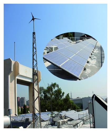
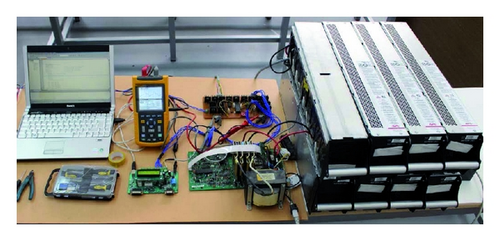
Configured PV-wind hybrid power system with battery backup was installed with the monitoring system in January 2009; wind turbine and PV array are shown in Figure 8. The monitoring system and battery bank, inverter, and DC-DC converters for PV and wind turbine were placed in the laboratory for ease of uploading the logged values which are presented in Figure 9.
For the assessment, the system was monitored for one-year period logged from January 2009 to January 2010. Battery voltage, load voltage, load current, battery current, PV output, and wind generator output currents have been measured with a sampling rate of 1 sec and recorded as 10 sec average values. Recorded data was uploaded to a computer, and thereafter daily, monthly, and yearly performance parameters have been calculated using these values of components and the hybrid system.
The data were analyzed following the International Electrotechnical Commission Standard (IEC) 61724 [38]. For PV, the methodology of the standard was followed and for the wind part, a similar approach is applied, mainly following the procedure proposed by Arribas et al. [39]. The results are given in Table 4. To test the effectiveness of the developed methodology, the studied PV-wind hybrid system performance parameters were also compared with simulation results.
| Parameter | Symbol | Measured | Units |
|---|---|---|---|
| Meteorological | |||
| Global direct irradiation | HI | 4.88 | kWh m−2d−1 |
|
EGAW | 0.36 | kWh m−2d−1 |
| Electrical energy quantities | |||
|
EPV | 811 | kWh |
| Net energy from the WT | EWT | 311 | kWh |
|
FPV | 0.71 | Dimensionless |
|
FWT | 0.29 | Dimensionless |
| Total energy in the system | Ein | 1142 | kWh |
| Total energy used | Euse | 822 | kWh |
| Net energy to the load | EL | 822 | kWh |
| BOS component performance | |||
| BOS efficiency | ηBOS | 72 | % |
| System performance indices | |||
| PV array yield | YPV | 4.4 | hd−1 |
| Final PV system yield | YfPV | 3.2 | hd−1 |
| Wind turbine yield | YWT | 0.57 | hd−1 |
| Final wind turbine yield | YfWT | 0.41 | hd−1 |
| Normalized losses | |||
| PV array capture losses | LcPV | 34.2 | % |
| PV BOS losses | LBOSPV | 28 | % |
|
RpPV | 41.4 | % |
| Wind turbine capture losses | LcWT | 27.7 | % |
| Wind BOS losses | LBOSWT | 37 | % |
|
RpWT | 46 | % |
| System efficiencies | |||
| Average PV efficiency | ηPVmean | 9.3 | % |
| Global PV efficiency | ηPVtot | 6.72 | % |
| Average WT efficiency | ηWTmean | 9.46 | % |
| Global WT efficiency | ηWTtot | 6.86 | % |
Inverter and charge regulator efficiencies were calculated, 93% and 98%, respectively. The battery bank efficiency was derived from measured parameters and calculated as 82%, which is 3 points less than the expected value. The overall system efficiency was calculated as 72%. Life cycle costs per kWh was calculated as $0.89 and LLP = 0.0428. Using the measured variables, hourly changes of SOC were calculated and the result is presented in Figure 10.
PV-wind hybrid power system directly converts solar and wind resources to electricity. This energy conversion process is void of gas emission. Consequently, one can say that it is entirely clean. But throughout the PV cell and wind turbine manufacturing processes and the transportation phase, they essentially consume a huge amount of energy; as a result, they emit considerable volume of greenhouse gases. PV systems emit 61 g CO2-equiv./kWh [40–42] and wind turbine emits 21 g CO2-equiv./kWh [43]. Accordingly, feeding load with the grid energy contributes to the greenhouse gasses emission. Table 5 compares the emissions caused by PV-wind hybrid system and grid-fed system. In Turkey, the energy from the grid is 76.1%, produced with fossil fuel such as natural gas, coal, and oil which are sources of greenhouse gasses emission where the other part of energy is supplied by mainly hydropower, wind, and geothermal resources. The grid-tied systems in Turkey have greenhouse gasses emission of 493 g CO2-equiv./kWh for 2011, and the electricity cost for the domestic user is 0.23 $/kWh [44]. When we compare the grid-tied system with the hybrid system, grid-tied consumers have greater emissions than autonomous PV-wind hybrid systems, while their cost is lower. The PV-wind hybrid system observes an important decrease of emission to 563.006 kg/year; on the other hand, hybrid system energy cost is very high compared to grid electricity cost. The other hybrid systems have the same environmental conditions as 1.7 kWh/m2-day; Panapakidis et al. calculated 0.975 $/kWh with 69% renewable fraction [45] and Dufo-López et al. calculated 0.647 $/kWh with 211 g CO2-equiv./kWh [46], whereas the studied system produces energy with a cost of 0.89 $/kWh and an emission of 82 g CO2-equiv./kWh.
| System | Electricity prices $/kWH |
Emissions g CO2-equiv./kWh |
Daily load kWh/day |
Total load kWh/year |
Total emissions g CO2-equiv./kWh |
|---|---|---|---|---|---|
| PV-wind hybrid | 0.89 | 82 | 3.0275 | 1142 | 92502 |
| Turkey grid | 0.23 | 493 | 3.0275 | 1142 | 563006 |
4. Conclusion
A sizing procedure of a hybrid PV-wind energy system was presented. The outlined technique defines optimum hybrid energy system configuration and control criteria. It needs hourly changing meteorological data as input and contributes cost-effective hybrid system configuration with highest reliability. The procedure was applied for the sizing of PV-wind hybrid energy system that is considered to lighting of the Solar Energy Institute Building. Configured hybrid system was installed in January 2009 and the system variations were measured every 1 minute during one year. From the measured values, life cycle costs per kWh were calculated as $0.89, LLP = 0.0428, and also hourly changes of SOC are shown in Figure 10. The validation of the procedure was performed through the comparison between simulation results and derived results obtained from measurements.
Nomenclature
-
- Cp:
-
- Power coefficient
-
- CC:
-
- Capital cost of hybrid system
-
- COP:
-
- Operation cost
-
- CSCPV:
-
- PV battery charger control switch
-
- CSCWT:
-
- WT battery charger control switch
-
- CSIN:
-
- Inverter control switch
-
- CSL:
-
- Load control switch
-
- fMM:
-
- Mismatch factor for different types of modules
-
- Ga,0:
-
- Reference irradiation
-
- Ga:
-
- Ambient irradiation
-
- :
-
- Reference short-circuit current
-
- :
-
- Short-circuit current of cell
-
- :
-
- Short-circuit current of module
-
- IM:
-
- Module current
-
- IPV:
-
- PV array current
-
- IW:
-
- Wind turbine current
-
- IBD:
-
- Battery discharge current
-
- ILoad:
-
- Load current
-
- IBC:
-
- Battery charge current
-
- :
-
- Equivalent serial resistance of module
-
- :
-
- Equivalent serial resistance of cell
-
- ηBC:
-
- Efficiency for the battery charger
-
- ηinv:
-
- Inverter efficiency
-
- NSBat:
-
- Number of series connected batteries
-
- NSC:
-
- Number of series connected cells
-
- NPC:
-
- Number of parallel connected cells
-
- NSM:
-
- Number of series connected modules
-
- NPM:
-
- Number of parallel connected modules
-
- NPBAT:
-
- Number of parallel connected batteries
-
- PBC-op:
-
- The output power of the battery charger
-
- σi:
-
- Self-discharge losses of the battery
-
- SOC:
-
- Battery stage of charge
-
- SOCmin:
-
- Minimum SOC
-
- SOCmax:
-
- Maximum SOC
-
- VBa:
-
- Voltage of a battery
-
- :
-
- Thermal voltage, mkTC/e
-
- ν:
-
- Wind speed (m/s)
-
- ρair:
-
- Air density.


