Design and Synchronization of Master-Slave Electronic Horizontal Platform System
Abstract
Horizontal platform system (HPS) is one of the mechanical systems with rich behavior and has extensively been applied in offshore and earthquake engineering. A corresponding electronic HPS is proposed in this paper to reduce the research cost and time when studying dynamics of the mechanical HPS. Furthermore, an output feedback controller is proposed for global synchronization between coupled electronic HPS systems and its stability condition is also derived by employing the Lyapunov stability theory. The experimental simulations verify the dynamics of the proposed electronic HPS and the synchronization effectiveness of the proposed control scheme.
1. Introduction
In recent years, the study for the dynamics analysis of chaotic systems has become a very popular research field [1–3]. A chaotic system is with several potential properties, such as highly complex dynamics, broad-band Fourier power spectrums, and strange attractors. Chaos synchronization has been found to be useful in many areas of physics and engineering systems such as those in power converters, flow dynamics and liquid mixing, biological systems, and information processing, especially in encryption and communication [4–8]. Beside that, many effective methods based on the experimental implementation for synchronization problems have been thoroughly investigated [1–10].
Horizontal platform system (HPS) is a mechanical system with rich chaos behavior, which can freely rotate around the horizontal axis and extensively applied in offshore and earthquake engineering [11] however, not as electronic circuits, to establish a mechanical system for research costs much time and money. In the present paper, we propose a corresponding electronic HPS model which has chaotic dynamics as the mechanical HPS owns. After establishing the electronic HPS, a new sufficient criterion for global chaos synchronization of two electronic HPS coupled by an output feedback controller is deduced. This method makes it possible to construct all of the state information from only a transmitted signal.
This paper is organized as follows. The original mechanical HPS is illustrated in Section 2. In Section 3, the corresponding electronic HPS is introduced and the corresponding chaotic behavior is verified. Section 4 formulates the design of an output feedback controller for synchronization of two identical electronic HPSs. The experimental simulations are given to verify the effectiveness of the proposed approach in Section 5. Finally, a concise conclusion is made in Section 6.
2. Mechanical Horizontal Platform System
3. The Corresponding Electronic HPS Model and Its Chaotic Behavior
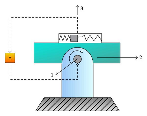
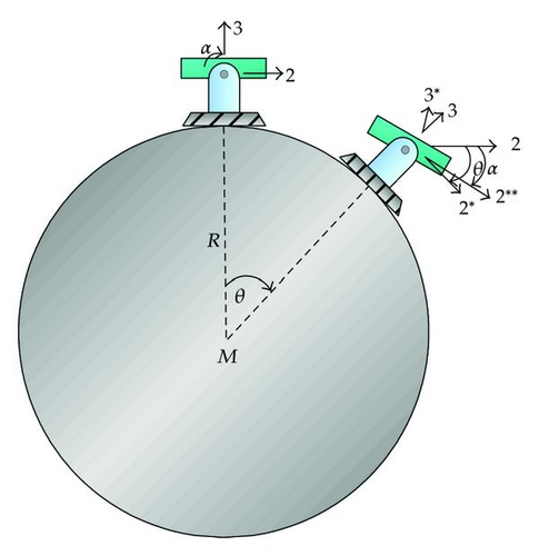
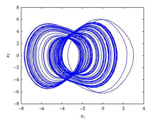
The typical parameters of HPS dynamics are given as A = 0.3, B = 0.5, C = 0.2, D = 0.4, r = 0.11559633, R = 6378000, g = 9.8, F = 3.4, and ω = 1.8, respectively. The phase portrait is illustrated in Figure 2. The largest Lyapunov exponent of electronic HPS is 0.3424; therefore, the chaotic behavior of the corresponding electronic HPS is guaranteed [13, 14].
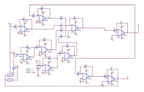
The electronic HPS circuit corresponding to the mechanical one is shown in Figure 2 which consists of one AC voltage (v4), two integral circuits (U1A, U6B), one addition circuit (U7A), and two nonlinear circuits (cos, sin). The state portrait of the proposed circuit is shown in Figure 3.
4. Output Feedback Design for Synchronizing the Coupled Electronic HPSs
In this section, we further propose a sufficient criterion for global chaos synchronization of two identical electronic HPSs coupled by an output feedback controller. Several works utilizing all states to fulfil the synchronization problem have been developed in the literature [4–8, 15–17]. In contrast to the previous works, this paper only uses the available output to construct the control scheme for achieving global synchronization. The main steps for designing the output feedback controller are stated as follows.
Step 1. Rewrite the HPS system (3.1) in the state space as
Let x = (x1, x2) T ∈ R2×1, the vector form of the system (4.1) is obtained as
Step 2. Define the master-slave systems as below, respectively.
Master system
Slave system
Defining the error vector , we have the following error dynamics:
The error dynamics (4.7) is further described as
Our goal is to select the coupling matrix L in (4.6) such that the orbits x(t) and of master-slave systems satisfy
Theorem 4.1. Suppose the feedback gain matrix L is selected such that
- (a)
and are observable and stable, respectively, where
(4.11) - (b)
the following Hamiltonian matrix H with some
(4.12)has no eigenvalues on the imaginary axis.
Then the master-slave system defined in (4.5) and (4.6) achieves global chaos synchronization.
The following lemmas will be needed for the main theorem.
Lemma 4.2 (see [18].)For any γ > 1, define the Hamiltonian matrix as (4.12); assume that (i) and are observable and stable, respectively, and (ii) H has no eigenvalues on the imaginary axis. Then the algebraic Riccati equation (ARE)
Proof. It is an immediate result of the work of Doyle et al. [18] and hence is omitted.
Lemma 4.3. For matrix Q(x) defined in (4.9), the following inequality holds:
Proof. By the differential mean-value theorem, we have
Proof of Theorem 4.1. Suppose the feedback gain matrix L is selected such that and are observable and stable, respectively. According to Lemma 4.2, if the Hamiltonian matrix (4.12) has no eigenvalue on the imaginary axis, then we have the following ARE:
5. Numerical Simulation
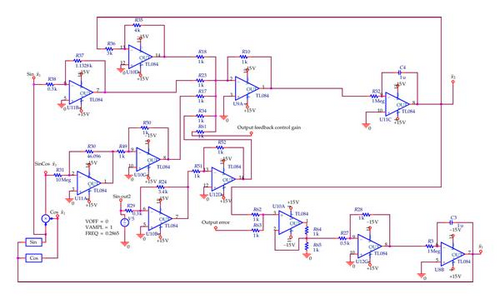
It is easy to check that the eigenvalues of H are [−1.042 + 1.5899i −1.042 − 1.5899i 1.042 + 1.5899i 1.042 − 1.5899i] and obviously no eigenvalues are on the imaginary axis. Thus according to Theorem 4.1, the master-slave system defined in (4.5) and (4.6) achieves global chaos synchronization. The controlled slave electronic HPS system is shown in Figure 4.
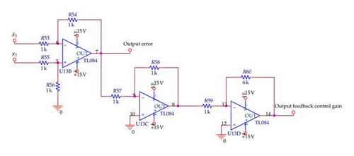
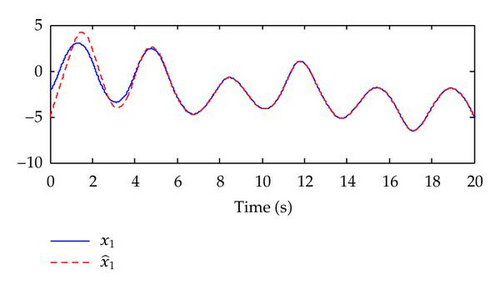
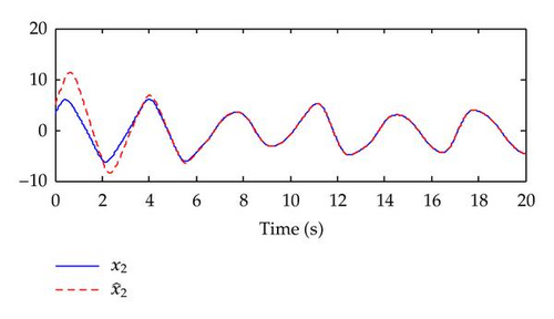
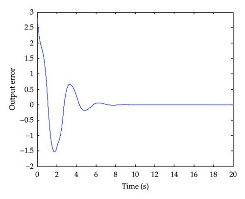
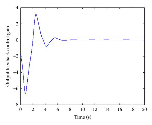
The simulation results are shown in Figures 5–7. The time responses of master and slave systems are shown in Figure 5. Figure 6 showing the time responses of output errors between master and slave systems. Finally, the output feedback control of is shown in Figure 7. The above simulation results show that the trajectories of master-slave systems are synchronized and the synchronization error surely converges to zero.
6. Conclusion
In this paper, two main results have been proposed. First, we have presented an electronic HPS model to reduce the cost and time when studying the mechanical one. Second, we have investigated the global chaos synchronization of two identical electronic horizontal platform systems only coupled by an output feedback control. A new sufficient criterion has been proposed based on the Lyapunov stability theory. Numerical simulations have verified the effectiveness of the proposed method.
Acknowledgment
This work was supported by the National Science Council of Republic of China under Contract 98-2221-E-006-192-MY3 and 100-2221-E-366-001.


