The Effects of Chemical Reaction, Hall, and Ion-Slip Currents on MHD Micropolar Fluid Flow with Thermal Diffusivity Using a Novel Numerical Technique
Abstract
The problem of magnetomicropolar fluid flow, heat, and mass transfer with suction through a porous medium is numerically analyzed. The problem was studied under the effects of chemical reaction, Hall, ion-slip currents, and variable thermal diffusivity. The governing fundamental conservation equations of mass, momentum, angular momentum, energy, and concentration are converted into a system of nonlinear ordinary differential equations by means of similarity transformation. The resulting system of coupled nonlinear ordinary differential equations is the then solved using a fairly new technique known as the successive linearization method together with the Chebyshev collocation method. A parametric study illustrating the influence of the magnetic strength, Hall and ion-slip currents, Eckert number, chemical reaction and permeability on the Nusselt and Sherwood numbers, skin friction coefficients, velocities, temperature, and concentration was carried out.
1. Introduction
Eringen [1] proposed the theory of micropolar fluids, which shows microrotation effects as well as microinertia, as these flow properties cannot be described by the classical Navier-Stokes theory. Since the pioneering work by Eringen, the theory of micropolar fluid has generated a lot of interest. Extension has been done, to include studies of magneto-micropolar fluid with Hall current and ion-slip currents with heat transfer due to vast possible engineering applications in areas like power generators, MHD accelerators, refrigeration coils, electric transformers, and heating elements. MHD flows of a viscous and incompressible fluid have been extensively studied with the effect of Hall current by Chamkha [2], Seddeek [3], Takhar et al. [4], Shateyi et al. [5, 6], Salem and Abd El-aziz [7], among others.
The momentum, heat, and mass transport on stretching sheet has several applications in polymer processing as well as in electrochemistry. The heat transfer problem associated with the boundary layer micropolar fluid under different physical conditions has been studied by several authors. Takhar et al. [8] considered diffusion of a chemical reactive species from a stretching sheet. Muthucumaraswamy and Ganesan [9] studied diffusion and first-order chemical reaction on impulsively started infinite vertical plate with variable temperature. Shateyi [10] investigated thermal radiation and buoyancy effects on heat and mass transfer over a semi-infinite stretching sheet with suction and blowing. Shateyi and Motsa [11] numerically investigated the unsteady heat, mass, and fluid transfer over a horizontal stretching sheet.
The porous media heat and mass transfer problems have several practical engineering applications such as geothermal systems, crude oil extraction, and ground-water pollution. The study of chemical reaction heat transfer in porous medium has important applications such as in tabular reactors, oxidation of solid materials, and synthesis of ceramic materials. Elgazery [12] numerically analyzed the effects of chemical reaction, Hall, ion-slip currents, variable viscosity and variable thermal diffusivity on the problem of magnetomicropolar fluid flow, heat and mass transfer with suction and blowing through a porous medium. Srinivasacharya and RamReddy [13] presented natural convection heat and mass transfer along a vertical plate embedded in a doubly stratified micropolar fluid saturated non-Darcy porous medium. Ishak et al. [14] investigated the unsteady boundary layer flow over a stretching permeable surface.
Elshehawey et al. [15] applied the Chebyshev finite-difference method to investigate the effects of Hall and ion-slip currents on magneto-hydrodynamic flow with variable thermal conductivity. Seddeek and Salama [16]. studied effects of chemical reaction and variable viscosity on hydromagnetic mixed convection heat and mass transfer for Hiemenz flow through porous media with radiation. Shateyi and Motsa [17] analyzed numerically the problem of magnetohydrodynamic flow and heat transfer of a viscous, incompressible and electrically conducting fluid past a semi-infinite unsteady stretching sheet with Hall currents, variable viscosity and thermal diffusivity. Mahmoud and Waheed [18] performed a theoretical analysis to study heat transfer characteristics of magnetohydrodynamic mixed convection flow of a micropolar fluid past a stretching surface with slip velocity at the surface and heat generation/absorption.
The aim of this work is to analyze the effects of chemical reaction, Hall and ion-slip currents on the MHD flow of a micropolar fluid through a porous medium using the successive linearization method (SLM). The SLM is based on a novel idea of iteratively linearizing the underlying governing nonlinear equations, which are written in similarity form, and solving the resulting equations using spectral methods. This approach has been successfully applied to different flow problem (see, e.g., Makukula et al. [19–22]; Shateyi and Motsa [17]; Motsa and Shateyi [23, 24]). The influences of the governing parameters on the flow characteristics are illustrated graphically and using tables.
2. Problem Formulation
We consider a steady, incompressible, magneto-micropolar and electrically conducting viscous fluid flowing over a horizontal plate in the x-direction under the influence of mass transfer with chemical reaction through a porous medium. We let the reaction of a species, say A with B be the first order homogeneous chemical reaction with a constant rate, κ. We also assume that the concentration of dissolved A is small enough and physical properties ρ and D are virtually constant throughout the fluid. The flow under consideration is also subjected to a strong transverse magnetic field B0 with a constant intensity along the y-axis (see Figure 1).
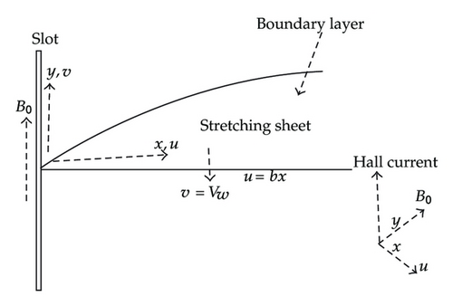
Generally, an electrically conducting fluid is affected by Hall and ion-slip currents in the presence of a magnetic field. The effect of Hall current gives rise to a force in the z-direction, which induces a cross-flow in the z-direction and hence the flow becomes three-dimensional.
3. Generalization of the Successive Linearisation Method (SLM)
4. Numerical Solution
5. Results and Discussion
In this section, we present the results obtained using both the successive linearization method and Chebyshev spectral collocation numerical method. The number of collocation points employed in this investigation is N = 50. The results are also validated against those obtained using the Matlab built-in solver bvp4c as well as reported by Elgazery [12]. Table 1 represents comparison between the SLM, Chebyshev pseudospectral method [12], and the bvp4c results of the local Nusselt number −θ′(0). We note from this table that the SLM and the bvp4c results match exactly but the results reported by Elgazery [12] are slightly different from the current results. This is an interesting observation, since Elgazery [12] also applied the pseudospectral method, this substantiate the claim that the SLM technique improves the accuracy of the Chebyshev method. We also note in this table that the absolute values of the Nusselt number decrease with increasing values of magnetic parameter and the ion-slip parameter. However, it increases with increasing values of the Hall parameter.
| M | βe | βi | [12] | Present | bvp4c |
|---|---|---|---|---|---|
| 0 | 5 | 0.4 | 0.327498 | 0.32749528 | 0.32749528 |
| 0.5 | 0.324844 | 0.32484164 | 0.32484164 | ||
| 1 | 0.321912 | 0.32190912 | 0.32190912 | ||
| 1.5 | 0.318772 | 0.31876809 | 0.31876809 | ||
| 0.3 | 0 | 0.311234 | 0.31122885 | 0.31122885 | |
| 1 | 0.319297 | 0.31929392 | 0.31929392 | ||
| 2 | 0.323083 | 0.32308061 | 0.32308061 | ||
| 0.3 | 5 | 0 | 0.326696 | 0.32669328 | 0.32669328 |
| 0.2 | 0.326225 | 0.32622274 | 0.32622274 | ||
| 0.5 | 0.325865 | 0.32586231 | 0.32586231 | ||
Table 2 gives the results of the wall stresses (Cfx) for various values of kp, N1, βe, and βi when other parameters are fixed. For fixed values of N1, we observe that the absolute values of the local-skin friction decrease with the increasing values of the permeability parameter (kp). The local shear stress (Cfx) increases in absolute values as the coupling parameter increases. The local wall shear stress (Cfx) increases in absolute values when the Hall parameter or ion-slip parameter increases.
| kp | N1 | βe | βi | 2nd-Order | 3rd-Order | 4th-Order | 6th-Order |
|---|---|---|---|---|---|---|---|
| 0.1 | 1 | 5 | 0.4 | −6.65334091 | −6.65334091 | −6.65334091 | −6.65334091 |
| 0.5 | 1 | 5 | 0.4 | −3.46988916 | −3.46989224 | −3.46989224 | −3.46989224 |
| 1 | 1 | 5 | 0.4 | −2.83779413 | −2.83787814 | −2.83787815 | −2.83787815 |
| 2 | 1 | 5 | 0.4 | −2.46510143 | −2.46622986 | −2.4662317 | −2.4662317 |
| 2 | 0.1 | 5 | 0.4 | −1.40914015 | −1.40961763 | −1.40961811 | −1.40961811 |
| 2 | 0.5 | 5 | 0.4 | −1.88961638 | −1.89034144 | −1.89034233 | −1.89034233 |
| 2 | 1 | 5 | 0.4 | −2.46510143 | −2.46622986 | −2.4662317 | −2.4662317 |
| 2 | 2 | 5 | 0.4 | −3.52816005 | −3.53067494 | −3.53068356 | −3.53068356 |
| 2 | 0.5 | 0 | 0.4 | −2.04791788 | −2.04807626 | −2.04807629 | −2.04807629 |
| 2 | 0.5 | 2 | 0.4 | −1.91920286 | −1.91972357 | −1.91972398 | −1.91972398 |
| 2 | 0.5 | 4 | 0.4 | −1.89445825 | −1.89514419 | −1.89514497 | −1.89514497 |
| 2 | 0.5 | 6 | 0.4 | −1.88649265 | −1.88724415 | −1.88724512 | −1.88724512 |
| 2 | 0.5 | 5 | 0 | −1.88077116 | −1.88155788 | −1.88155895 | −1.88155895 |
| 2 | 0.5 | 5 | 2 | −1.88698782 | −1.88774243 | −1.88774341 | −1.88774341 |
| 2 | 0.5 | 5 | 4 | −1.8814535 | −1.88225343 | −1.88225455 | −1.88225455 |
| 2 | 0.5 | 5 | 6 | −1.8789626 | −1.87978367 | −1.87978486 | −1.87978486 |
The values of the wall shear stresses (Cfx, Cfz), the local Nusselt number −θ′(0) and the local Sherwood number −ϕ′(0) for different Hartman number M, Hall parameter βe, ion-slip parameter βi, and coupling parameter N1 are presented in Table 3. It is observed in this table that the local skin-friction coefficients f′′(0) and g′(0) increase with increasing values of M and N1 but g′(0) decreases as values of βe and βi increase. Both the local Nusselt number and the Sherwood number are found to be decreasing with increasing values of the Hartman number M and they also slightly decrease with increasing values of the ion-slip parameter and the coupling parameter. The local Nusselt number and the Sherwood number increases as Hall currents increase.
| M | βe | βi | N1 | Cfx | Cfz | −θ′(0) | −ϕ′(0) |
|---|---|---|---|---|---|---|---|
| 1 | 5 | 0.4 | 0.2 | −1.56322914 | 0.08599136 | 0.32190912 | 0.48724548 |
| 2 | 5 | 0.4 | 0.2 | −1.61077402 | 0.16422572 | 0.31547847 | 0.48232094 |
| 3 | 5 | 0.4 | 0.2 | −1.65972336 | 0.23554336 | 0.30864336 | 0.47715106 |
| 4 | 5 | 0.4 | 0.2 | −1.70922564 | 0.3008927 | 0.30169844 | 0.47195166 |
| 5 | 5 | 0.4 | 0.2 | −1.75872895 | 0.3611565 | 0.29482895 | 0.4668536 |
| 0.3 | 0 | 0.4 | 0.2 | −1.65812419 | 0 | 0.31122885 | 0.47941184 |
| 0.3 | 2 | 0.4 | 0.2 | −1.55508122 | 0.04885996 | 0.32308061 | 0.48818323 |
| 0.3 | 4 | 0.4 | 0.2 | −1.53530214 | 0.03171899 | 0.32547247 | 0.49001302 |
| 0.3 | 6 | 0.4 | 0.2 | −1.52894206 | 0.02291991 | 0.32624205 | 0.49060833 |
| 0.3 | 5 | 0 | 0.2 | −1.52437745 | 0.03510497 | 0.32669328 | 0.49098971 |
| 0.3 | 5 | 0.5 | 0.2 | −1.53222519 | 0.02430318 | 0.32586231 | 0.49030887 |
| 0.3 | 5 | 1 | 0.2 | −1.53273738 | 0.01483309 | 0.32583913 | 0.49027923 |
| 0.3 | 5 | 1.5 | 0.2 | −1.53110355 | 0.00931987 | 0.32603778 | 0.49043266 |
| 0.3 | 5 | 0.5 | 0 | −1.28738139 | 0.02038592 | 0.32757864 | 0.49138014 |
| 0.3 | 5 | 0.5 | 0.2 | −1.53222519 | 0.02430318 | 0.32586231 | 0.49030887 |
| 0.3 | 5 | 0.5 | 0.5 | −1.89132586 | 0.03006273 | 0.32307538 | 0.48858611 |
| 0.3 | 5 | 0.5 | 1 | −2.46753529 | 0.03931368 | 0.31775592 | 0.48535366 |
Graphical representation of the numerical results are illustrated in Figure 5 through Figure 13 to depict the influence of different parameters on the flow characteristics. Figure 5 depicts the effects of the Hall current parameter βe on the velocity components f′(η) and g(η). We see that the stream velocity profiles f′(η) increases as βe increases. We also observe in this figure that velocity distribution across the stretching sheet g(η) increases with increasing values of βe when βe ≤ 1 but decreases with increasing values of βe greater than unity.
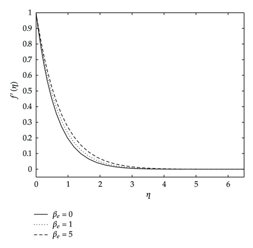
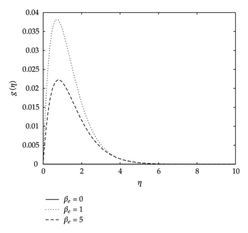
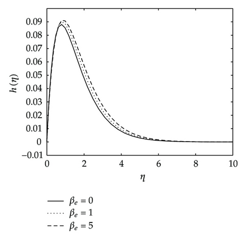
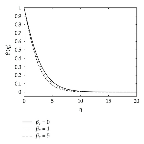
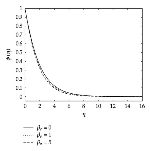
Figure 6 depicts the effects of the Hall current parameter βe on the angular velocity h(η), temperature and concentration distributions. We observe that the angular velocity steeply rises up to maximum peaks as the Hall parameter increases. In the same figure we see that both the temperature and concentration profiles approach their classical values when the Hall parameter βe becomes large. They both decrease with increasing values of βe.
The influence of the Hartman number on the stream velocity and the velocity across the plate is depicted in Figure 7. It is observed that the stream velocity of the fluid decreases with the increase of the magnetic field parameter values. The decrease in this velocity component as the Hartman number (M) increases is because the presence of a magnetic field in an electrically conducting fluid introduces a force called the Lorentz force, which acts against the flow if the magnetic field is applied in the normal direction, as in the present study. This resistive force slows down the fluid velocity component as shown in Figure 7. In Figure 7 we have the influence of the magnetic field parameter on the lateral velocity. It can be seen that as the values of this parameter increase, the lateral velocity increases.
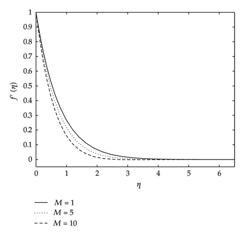
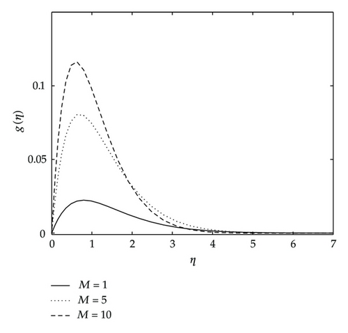
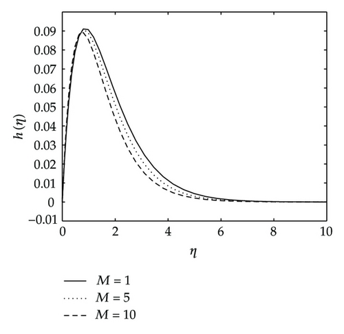
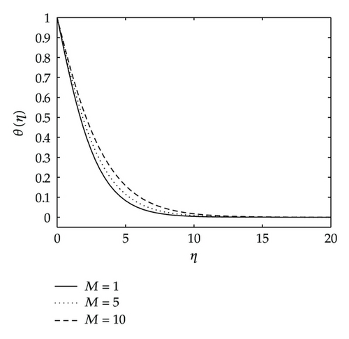
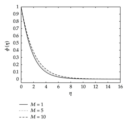
Figure 8 shows the effects of the magnetic parameter M on the angular velocity h(η), temperature and concentration profiles. As expected, the angular velocity steeply increases with every value of the magnetic value until attaining a peak and thereafter the angular velocity decreases monotonically with increasing values of M. In this figure, we also observe that both the temperature and concentration boundary layers become thick as values of the magnetic parameter increase. The effects of a transverse give rise to a resistive-type force called the Lorentz force. This force has the tendency to slow down the motion of the fluid and increase its thermal and concentration boundary layers hence increasing the temperature and concentration fields of the flow.
Figures 9 and 10 give the effects of the permeability parameter kp on the velocity components, temperature and concentration distributions. As shown in these figures, all the velocity components are increasing with increasing values of the permeability parameter, whereas the temperature and concentration decrease as the permeability parameter kp increases. Physically, this means that the porous medium impact on the boundary layer growth is significant due to the increase in the thickness of the thermal and concentration boundary layers. It is expected that, an increase in the permeability of porous medium lead to a rise in the flow of the fluid through it, since when the holes of the porous medium become large, the resistance of the medium may be neglected. Figure 11 depicts the effects of coupling constant or material parameter on the velocity components. The stream velocity is slightly affected by the coupling constant. As we move away from the stretching sheet surface, η > 1, the stream velocity decreases as N1 increases. We observe also in Figure 11 that the velocity across the plate monotonically decreases as N1 increases. We observe in Figure 11 that for values of η less than two, the angular velocity increases when N1 increases, and thereafter we have a cross-flow angular velocity when increasing values of N1 cause the angular velocity to decrease.
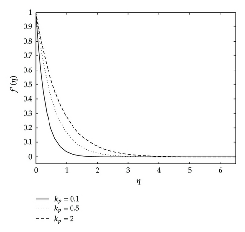
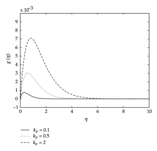
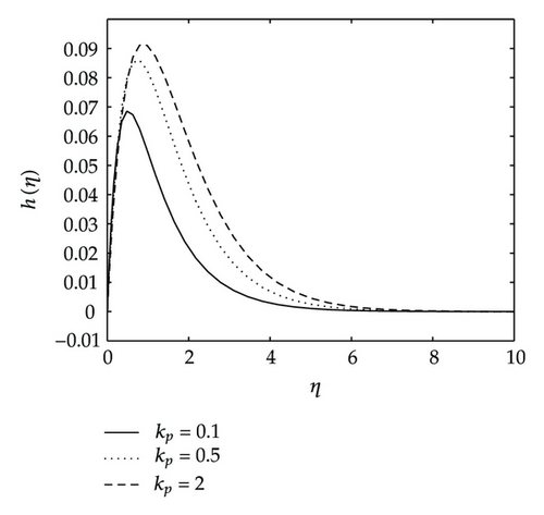
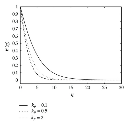
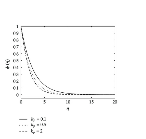
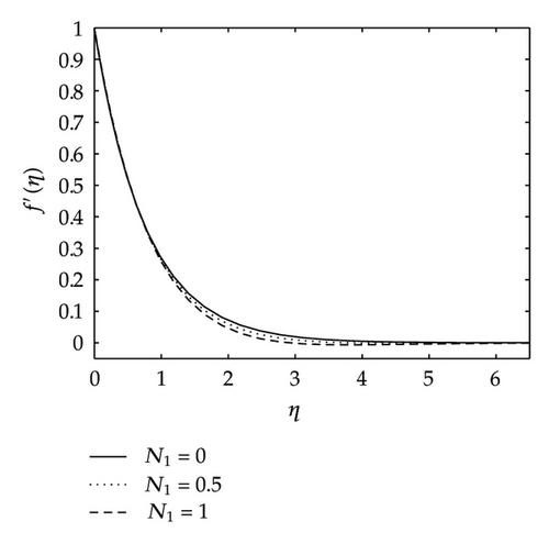
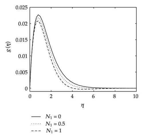
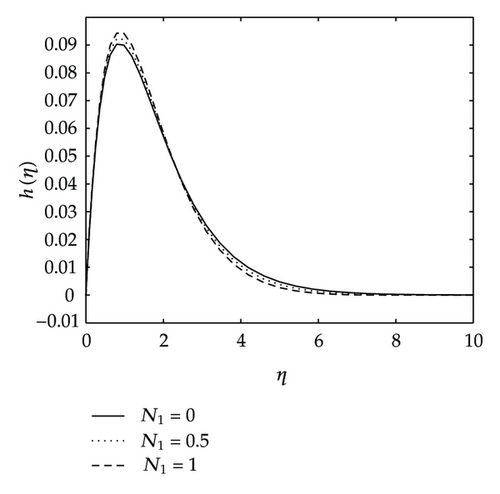
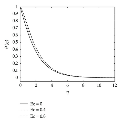
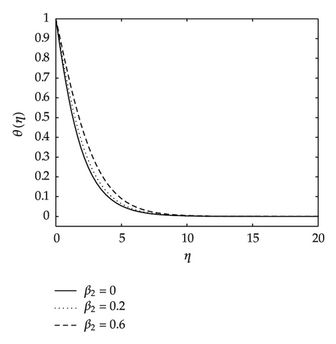
Figure 12 shows the effects of the Eckert number Ec and the variable thermal diffusivity parameter β2 on the temperature. The temperature distribution θ(η) increases as Ec and β2 increase as shown in Figure 12.
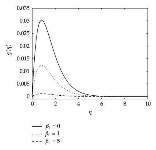
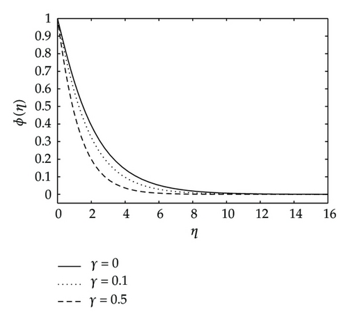
Finally, Figure 13 shows the effects of the ion-slip parameter βi on the velocity across the plate g(η) and those of the chemical reaction on the concentration distribution ϕ(η). We observe in this figure that the ion-slip parameter has a significant effect on the induced velocity in the z-direction. The velocity component decreases with increases in the parameter βi. We also observe in this study (not shown for brevity) that f′(η), h(η), and θ(η) profiles increase as the ion-slip parameter increases. From Figure 13 we also observe that the effects of chemical reaction parameter is to reduce the concentration distribution ϕ(η) when γ increases.
6. Conclusions
In this study, the effects of Hall and ion-slip currents, chemical reaction and variable thermal diffusivity on magnetomicropolar fluid flow through a porous medium past a stretching sheet in the presence of heat and mass transfer have been numerically analyzed using the successive linearization method together with Chebyshevcollocation method. Results for the wall stresses, local Nusselt and Sherwood numbers as well as the details of the velocities, temperature and concentration distributions are presented in tabular and/or graphical forms for the governing parameters. The successive linearization method was found to be a very efficient and accurate method which we hope to apply to different problems in fluid mechanics and related fields. The study observed that higher values of the coupling parameter results in lower stream velocity and velocity across the plate but have little effects on the angular velocity. The porous medium impact on the boundary layer growth is significant due to the increase in the thickness of the hydrodynamic boundary layer and the decrease in the thickness of the thermal and concentration boundary layers. All the velocity components increase with increasing values of the Hall current. The ion-slip current causes the induced velocity in the z-direction to decrease but has opposing effects on the stream velocity, angular velocity, as well as temperature profiles.
Acknowledgment
The authors wish to acknowledge financial support from the University of Swaziland, University of Venda, and the National Research Foundation (NRF).


