Volume 2012, Issue 1 293709
Research Article
Open Access

Active Sliding Mode Control Antisynchronization of Chaotic Systems with Uncertainties and External Disturbances

Wafaa Jawaada

Corresponding Author

Wafaa Jawaada

School of Mathematical Sciences, Universiti Kebangsaan Malaysia, Selangor, 43600 Bangi, Malaysia ukm.my

Search for more papers by this author
M. S. M. Noorani

M. S. M. Noorani

School of Mathematical Sciences, Universiti Kebangsaan Malaysia, Selangor, 43600 Bangi, Malaysia ukm.my

Search for more papers by this author
M. Mossa Al-sawalha

M. Mossa Al-sawalha

Mathematics Department, Faculty of Science, University of Hail, Hail 81451, Saudi Arabia uoh.edu.sa

Search for more papers by this author
First published: 08 April 2012
Citations: 4
Academic Editor: Debasish Roy

Abstract

The antisynchronization behavior of chaotic systems with parametric uncertainties and external disturbances is explored by using robust active sliding mode control method. The sufficient conditions for achieving robust antisynchronization of two identical chaotic systems with different initial conditions and two different chaotic systems with terms of uncertainties and external disturbances are derived based on the Lyapunov stability theory. Analysis and numerical simulations are shown for validation purposes.

1. Introduction

Chaotic nonlinear systems appear ubiquitously in nature and can occur in man-made systems. These systems are recognized by their great sensitivity to initial conditions. Many scientists who are interested in this field have struggled to achieve the synchronization or antisynchronization of different chaotic systems, mainly due to its potential applications especially in chemical reactions, power converters, biological systems, information processing, secure communications, and so forth [17]. But due to its complexities, such tasks are always difficult to achieve. It is much more attractive and challenging to realize the synchronization or antisynchronization of two different chaotic systems especially if terms of uncertainty are considered. A wide variety of approaches have been proposed for the synchronization or antisynchronization of chaotic systems, which include generalized active control [810], nonlinear control [11, 12], adaptive control [1317], and sliding mode control [18, 19]. Most of the above-mentioned works did not consider the uncertainty of parameters and its effects on the systems. The aim of this paper is to further develop the state observer method for constructing antisynchronized slave system for chaotic systems with parametric uncertainties and external disturbances by using a robust active sliding mode method.

The outline of the rest of the paper is organized as follows. Firstly, in Section 2 we present a novel active sliding mode controller design and analysis. Section 3 presents a brief description of the two systems, Next, in Section 4, the active sliding mode control method is applied to antisynchronize two identical chaotic systems with different initial conditions and terms of uncertainties and external disturbances. In Section 5, we apply our method to antisynchronize two different chaotic systems, namely, the chaotic Lü and Genesio systems. Finally, Section 6 provides a summary of our results.

2. Active Sliding Mode Controller Design and Analysis

Design procedure of the active sliding mode controller which is a combination of the active controller and the sliding mode controller is given first, and then the stability issue of the proposed method is discussed.

2.1. Active Sliding Mode Controller Design

Consider a chaotic system described by the following nonlinear differential equation:
()
where x(t) ∈ Rn denotes the system’s n-dimensional state vector, A1Rn×n represents the linear part of the system dynamics, and f1 : RnRn is the nonlinear part of the system, ΔA1Rn×n is the matrix of uncertainties, and D1(t) ∈ Rn is a vector representing external disturbances. Relation (2.1) represents the master system. The controller u(t) ∈ Rn is added into the slave system, so it is given by
()
where y(t) ∈ Rn is the slave system’s n-dimensional state vector, A2Rn×n and f2 : RnRn play similar roles as A1 and f1 for the master system, ΔA2Rn×n is the matrix uncertainties, and D2(t) ∈ Rn is a vector representing external disturbances. If A1 = A2 and f1(·) = f2(·), then x and y are the states of two identical chaotic systems. Otherwise they represent the states of two different chaotic systems. The antisynchronization problem is to design the controller u(t) ∈ Rn which antisynchronizes the states of the master and slave systems. The dynamics of the antisynchronization errors can be expressed as
()
where e = y + x and F(x, y) = f2(y) + f1(x) + (A1 − (A2 + ΔA2))x − ΔA1y. Our goal is to design the controller u(t) ∈ Rn such that
()
where ∥·∥ is the Euclidean norm. As the trajectories of the chaotic systems are always bounded, then one can assume uncertainties to be bounded, so, in general,
()
where ρ, μ, δ, and ϵ are positive constants. According to the active control design procedure, one uses the control input u(t) to eliminate the nonlinear part of the error dynamics. In other words, the input vector is considered as
()
The error system (2.3) is then rewritten as
()
Equation (2.7) describes the error dynamics with a newly defined control input H(t). There are many possible choices for the control H(t). Without loss of generality, we choose the sliding mode control law as follows:
()
where is a constant gain vector and w(t) ∈ R is the control input that satisfies
()
and s = s(e) is a switching surface which prescribes the desired dynamics. The resultant error dynamics is then
()
In what follows, the appropriate sliding mode controller will be designed according to the sliding mode control theory.

2.1.1. Sliding Surface Design

The sliding surface can be defined as follows:
()
where C = [c1, c2, c3] is a constant vector. The equivalent control approach is found by the fact that is a necessary condition for the state trajectory to stay on the switching surface s(e) = 0. Hence, when in sliding mode, the controlled system satisfies the following conditions:
()
()
Now, using (2.10), (2.11), and (2.12), one can obtain
()
Solving (2.14) for w(t) results in the equivalent control weq(t)
()
where the existence of (CK)−1 is a necessary condition. Replacing for w(t) in (2.10) from weq(t) of (2.15), the state equation in the sliding mode is determined as follows:
()
As long as the system (2.10) has all eigenvalues with negative real parts, it is asymptotically stable.

2.1.2. Design of the Sliding Mode Controller

We assume that the constant plus proportional rate reaching law is applied. The reaching law can be chosen such that
()
where γ is a positive real number. The gains q > 0 and r > 0 are determined such that the sliding condition is satisfied and the sliding mode motion occurred. From (2.10) and (2.11), it can be found that
()
Now, from (2.17) and (2.18), the control input is determined as
()

2.1.3. Stability Analysis

To check the stability of the controlled system, one can consider the following Lyapunov candidate function:
()
The time derivative of (2.21) is
()
Since s2/(|s| + γ) > 0,   r > 0 and q > 0, we have ; therefore, is negative definite. This property implies boundedness of the sliding surface s. The error dynamics can be obtained using (2.19) in (2.10):
()
As a linear system with bounded input (−K(CK)−1q  for  s ≥ 0  and  K(CK)−1q  for  s < 0), the error system is asymptotically stable if and only if [(A2 + ΔA2 + ΔA1) − K(CK)−1C(rI + (A2 + ΔA2 + ΔA1))] has negative eigenvalues. Because of the special structure for matrix A2 in the given chaotic systems, one of the eigenvalues is always −r and therefore is stable. The two other eigenvalues are independent from r and determined by the other control parameters that is, K and C. The latter two eigenvalues can be negative or positive depending on K and C values. By appropriate choices of r, K, and C, one is able not only to stabilize the error system but also to adjust the rate of the error convergence. The parameter q can be used to enhance the robust property expected from a sliding mode controller.

3. Systems Description

The Lü attractor, which connects the Lorenz attractor [20] and Chen and Ueta attractor [21, 22] and represents the transition from one to another, was proposed and analyzed by lü et al. [23]. The Lü chaotic system is described by the following system of differential equations:
()
where x, y, and z are state variables and a, b, and c are positive parameters. This system is dissipative for c < a + b and has a chaotic attractor when a = 36, b = 3, and c = 20. The Genesio system was introduced by Genesio and Tesi in [24]. It is given by
()
where x, y, and z are state variables, and a, b, and c are the positive real constants satisfying ab < c. Throughout this paper, we set a = 1.2, b = 2.92, and c = 6 such that the system exhibits chaotic behavior.

4. Active Sliding Mode Antisynchronization between Two Identical Systems

In order to observe synchronization behavior between two identical chaotic systems via active sliding mode control, we consider two examples, the first one is Lü system in (3.1) and the second example is Genesio system which is described in (3.2).

4.1. Active Sliding Mode Antisynchronization between Two Identical Lü Systems
For the Lü system, let us consider that
()
The master system and the slave system can be written as the following respectively:
()
and the slave system can be written as
()
where u1, u2, u3 are three control functions to be designed in order to determine the control functions and to realize the active sliding mode antisynchronization between the systems in (4.2) and (4.3). We add (4.2) and (4.3) to get
()
where e1 = x2 + x1,   e2 = y2 + y1, and e3 = z2 + z1. Our goal is to find proper control functions ui  (i = 1,2, 3) such that system equation (4.3) globally antisynchronizes system equation (4.2) asymptotically; that is,
()
where . Without the controls (ui = 0,   i = 1,2, 3), the trajectories of the two systems equations (4.2) and (4.3), will quickly separate with each other and become irrelevant. However, when controls are applied, the two systems will approach synchronization for any initial conditions by appropriate control functions. If the control parameters are chosen as C = (0,1, 1),   K = (1,1,0)T, and r = 1, q = 30, and γ = 0.01, then the switching surface
()
so the controllers are:
()
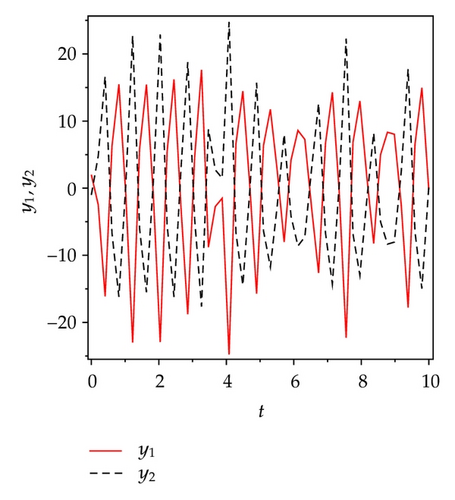
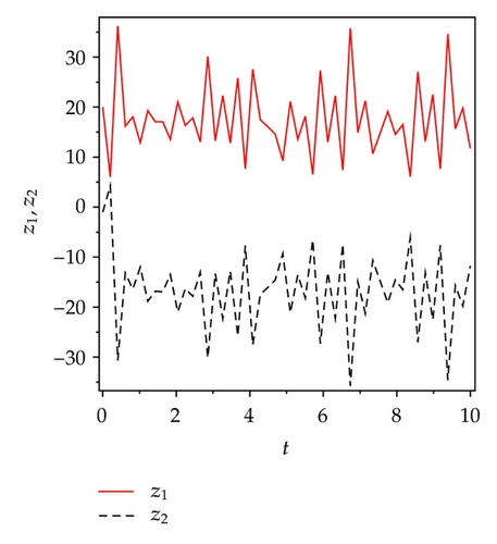
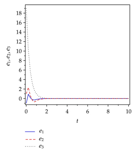
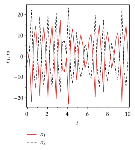
Applying controller (4.7) to the slave system then the slave system in (4.3) can synchronize master system equation (4.2) asymptotically.To verify and demonstrate the effectiveness of the proposed method, we discuss the simulation result for the active sliding mode antisynchronization between two identical Lü systems. For these simulations, the fourth-order Runge-Kutta method is used to solve the systems with time step size 0.001. We assumed that the initial conditions, (x1(0), y1(0), z1(0)) = (2,2, 20) and (x2(0), y2(0), z2(0)) = (−3, −1, −1). Hence the error system has the initial values e1(0) = −1,   e2(0) = 1, and e3(0) = 19. The systems parameters are chosen as a = 36,   b = 3, c = 20 in the simulations such that Lü system exhibit chaotic behavior. Antisynchronization of the systems equations (4.3) and (4.2) via active sliding mode controllers in (4.7) is shown in Figure 1. Figures 1(a)1(c) display the state trajectories of master system (4.2) and slave system (4.3). Figure 1(d) displays the error signals e1, e2, e3 of the Lü system under the controller equations (4.7).
Details are in the caption following the image
State trajectories of drive system (4.2) and response system (4.3), (a) signals x1 and x2; (b) signals y1 and y2; (c) signals z1 and z2; (d) the error signals e1, e2, e3 between two identical Lü systems with different initial conditions under the controller (4.7).

4.2. Active Sliding Mode Antisynchronization between Two Identical Genesio Systems
For the Genesio system, let us consider that
()
The master system and the the slave system can be written as the following; respectively,
()
and the slave system can be written as
()
where u1, u2, u3 are three control functions to be designed in order to determine the control functions and to realize the active sliding mode antisynchronization between the systems in (4.9) and (4.10). We add (4.9) and (4.10) to get
()
where e1 = x2 + x1,   e2 = y2 + y1 and e3 = z2 + z1. Our goal is to find proper control functions ui  (i = 1,2, 3) such that system equation (4.10) globally antisynchronizes system equation (4.9) asymptotically, that is,
()
where . Without the controls (ui = 0,   i = 1,2, 3), the trajectories of the two systems, (4.9) and (4.10), will quickly separate with each other and become irrelevant. However, when controls are applied, the two systems will approach synchronization for any initial conditions by appropriate control functions. if the control parameters are chosen as C = (6,0, −1), K = (1,0,0)T, and r = 1, q = 60, and γ = 0.01, then the switching surface
()
so the controllers are
()
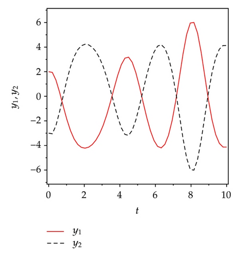
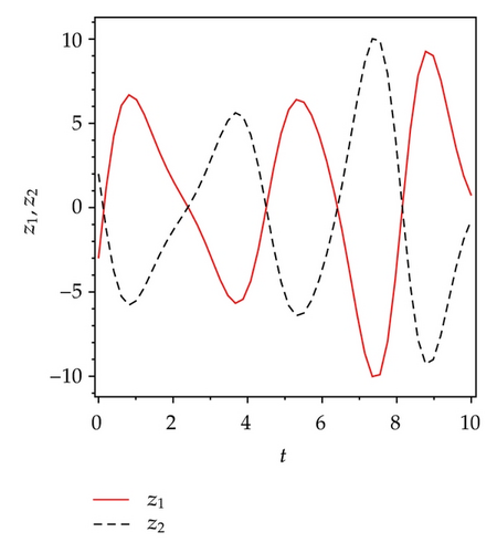
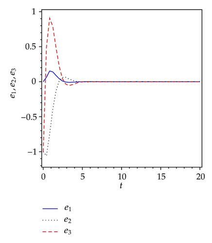
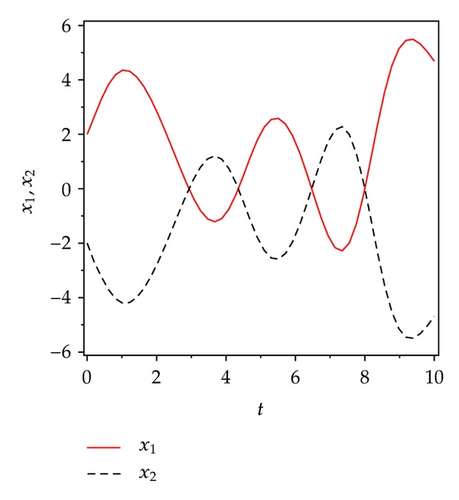
Applying controller (4.14) to the slave system then the slave system, in (4.10) can synchronize master system equation (4.9) asymptotically. In the following, we discuss the simulation results of the proposed method. For these simulations, the fourth-order Runge-Kutta method is used to solve the systems with time step size 0.001. We assumed that the initial conditions, (x1(0), y1(0), z1(0)) = (2,2, 2) and (x2(0), y2(0), z2(0)) = (−2, −3, −3). Hence the error system has the initial values e1(0) = 0,   e2(0) = −1, and e3(0) = −1. The systems parameters are chosen as a = 1.2,   b = 2.92, and c = 6 in the simulations such that both systems exhibit chaotic behavior. Antisynchronization of the systems equations (4.10) and (4.9) via active sliding mode controllers in (4.14) are shown in Figure 2. Figures 2(a)2(c) display the state trajectories of master system (4.9) and slave system (4.10). Figure 2(d) display the error signals e1, e2, e3 of Genesio system under the controller equations (4.14).
Details are in the caption following the image
State trajectories of drive system (4.9) and response system (4.10), (a) signals x1 and x2; (b) signals y1 and y2; (c) signals z1 and z2; (d) the error signals e1, e2, e3 between two identical Genesio systems with different initial conditions under the controller (4.14).

5. Active Sliding Mode Antisynchronization between Two Different Systems

In this section the antisynchronization behavior between two different chaotic systems via active sliding mode control is investigated, the Lü system in (3.1) is assumed as the master system and the Genesio system in (3.2) is taken as the slave system. If we take:
()
Here is the master and slave systems; respectively,
()
()
We add (5.2) to (5.3) to get
()
where e1 = x2 + x1,   e2 = y2 + y1, and e3 = z2 + z1. So we are aiming to find proper control functions ui  (i = 1,2, 3) such that system equation (5.3) globally antisynchronizes system equation (5.2) asymptotically; that is,
()
where .
If the control parameters are chosen as C = (0,1, −1),   K = (0,1,0)T and r = 1, q = 10 and γ = 0.01 then the switching surface
()
()
using (5.7) we get
()

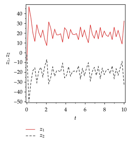
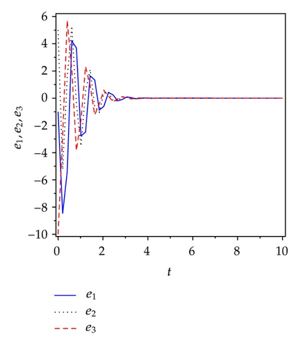
Applying controllers in (5.8), slave system equation (5.3) can antisynchronize master system equation (5.2) asymptotically. To verify and demonstrate the effectiveness of the proposed method, we discuss the simulation result for the active sliding mode antisynchronization between the Lü system and the Genesio system. In the numerical simulations, the fourth-order Runge-Kutta method is used to solve the systems with time step size 0.001. For this numerical simulation, we assumed that the initial conditions (x1(0), y1(0), z1(0)) = (−3,2, −8) and (x2(0), y2(0), z2(0)) = (2,3, −2). Hence the error system has the initial values e1(0) = −1,   e2(0) = 5, and e3(0) = −10. The system parameters are chosen as a1 = 36,   b1 = 3,   c1 = 20, and a2 = 1.2,   b2 = 2.92,   c2 = 6 in the simulations such that both systems exhibit chaotic behavior. Antisynchronization of the systems equations (5.2) and (5.3) via active sliding mode control law in (5.8) are shown in Figure 3. Figures 3(a)3(c) display the state trajectories of master system (5.2) and slave system (5.3). Figure 3(d) displays the error signals e1, e2, e3 of the Lü system and the Genesio system under the controller equations (5.8).
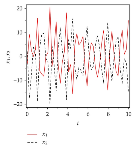
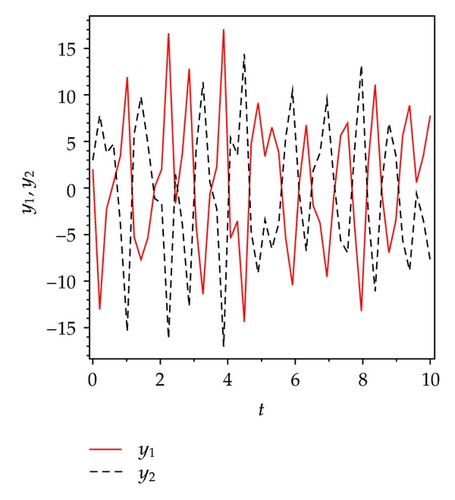
Details are in the caption following the image
State trajectories of drive system (5.2) and response system (5.3), (a) signals x1 and x2; (b) signals y1 and y2; (c) signals z1 and z2; (d) the error signals e1, e2, e3 between the Lü system and the Genesio system under the controller (5.8).
Details are in the caption following the image
State trajectories of drive system (5.2) and response system (5.3), (a) signals x1 and x2; (b) signals y1 and y2; (c) signals z1 and z2; (d) the error signals e1, e2, e3 between the Lü system and the Genesio system under the controller (5.8).
Details are in the caption following the image
State trajectories of drive system (5.2) and response system (5.3), (a) signals x1 and x2; (b) signals y1 and y2; (c) signals z1 and z2; (d) the error signals e1, e2, e3 between the Lü system and the Genesio system under the controller (5.8).
Details are in the caption following the image
State trajectories of drive system (5.2) and response system (5.3), (a) signals x1 and x2; (b) signals y1 and y2; (c) signals z1 and z2; (d) the error signals e1, e2, e3 between the Lü system and the Genesio system under the controller (5.8).

6. Concluding Remark

In this paper, we have applied the antisynchronization to some chaotic systems with parametric uncertainties and external disturbances via active sliding mode control. We have proposed a novel robust active sliding mode control scheme for asymptotic chaos antisynchronization by using the Lyapunov stability theory. Finally, the numerical simulations proved the robustness and effectiveness of our method.

Acknowledgment

This work is financially supported by the Universiti Kebangsaan Malaysia Grant: UKM-DLP-2011-016.

      The full text of this article hosted at iucr.org is unavailable due to technical difficulties.