Lag Synchronization of Coupled Multidelay Systems
Abstract
Chaos synchronization is an active topic, and its possible applications have been studied extensively. In this paper we present an improved method for lag synchronization of chaotic systems with coupled multidelay. The Lyapunov theory is used to consider the sufficient condition for synchronization. The specific examples will demonstrate and verify the effectiveness of the proposed approach.
1. Introduction
Since synchronization of chaotic systems was first realized by Fujisaka and Yamada [1] and Pecora and Carroll [2], chaos synchronization has received increasing interest and has become an active research topic. Currently its possible applications in various fields are in great interest, for example, applications to control theory [3], telecommunications [4–7], biology [8, 9], lasers [10, 11], secure communications [12], and so on.
Roughly speaking, chaotic communication schemes rely on the synchronization technique: the information signal is mixed at the master, and a driving signal is then generated and is sent to the slave; as a result, their chaotic trajectories remain in step with each other during temporal evolution. Besides identical synchronization [13], several new types of chaos synchronization of coupled oscillators have occurred, that is, generalized synchronization [12], phase synchronization [14], lag synchronization [15], anticipation synchronization [16], and projective synchronization [17].
Lag synchronization can be realized when the strength of the coupling between phase-synchronized oscillators is increased. There, the driving signal is constituted by the sum of multiple nonlinear transformations of delayed state variable [18]. Master and slave′s formulas are in the form of single delay [19, 20] and multidelay [21–23]. From the application point of view, this new multidelay synchronization, different from conventional synchronization without lag, offers a significant advantage in terms of security of communication. Since the constructed state variable of the master system with lag becomes more complex than that of the conventional system, multilag systems achieve high security. Intruders cannot reconstruct the attractors of driving signal by using conventional reconstruction methods [24, 25] so as not to decipher the transferred message.
In the present paper, we proposed a systematic and rigorous scheme for lag synchronization of coupled multidelay systems based on the Lyapunov stability theory. Furthermore, the zero solution of lag synchronization differential equation is globally asymptotically stable. The effectiveness of the proposed scheme is confirmed by the numerical simulation of specific example.
2. The Schemes of Lag Synchronization
2.1. The Proposed Lag Synchronization Model
Lag synchronization was first investigated by Rosenblum [15], and it can be considered that the state variable of the slave is delayed by the positive time lag τd in comparison with that of the master while their amplitudes follow each other, that is, lim t→∞|y(t) − x(t − τd)| = 0.
We consider the following model of lag synchronization.
2.2. Proof for the Lag Synchronization Model
The desired synchronization manifold is expressed by the following relation y(t) → x(t − τd) as t → ∞, where τd is a lag time.
We choose suitable DS(t) to satisfy e(t) = y(t) − x(t − τd) → 0 as t → ∞.
Assumption 2.1. Q = P + R − I, I < min {P, Q, R} where I is integer. When i = 1, …, I, fi ≡ gi ≡ hi,
Assumption 2.2. When j = 1, …, (P − I), gI+j ≡ fI+j,
Assumption 2.3. Nonlinearity fi (i = 1, …, I) satisfies Lipshitz condition; that is, there exists a positive constant L for all time variables a and b, such that |fi(a + b) − fi(a)| ≤ L|b| (i = 1, …, I).
Here we give the sufficient condition for system synchronization.
Theorem 2.4. If the system (2.1), (2.2), and (2.3) satisfies Assumptions 2.1, 2.2, and 2.3 and if
Proof. The dynamics of synchronization error is
By applying Assumption 2.1, (2.8) can be rewritten as
By applying Assumption 2.2, if Q − I = (P − I) + (R − I) and y(t − γi) = x(t − γi − τd) + e(t − γi), we have
Define a Lyapunov function [26] as
Then, we obtain
Here, we have
According to Assumption 2.1, we have
In our model, can be rewritten as (1/2)Ie2(t). By Assumption 2.3, we have
According to 2xy ≤ x2 + y2, where x, y ∈ ℜ, we get
Finally, we obtain
The proof is completed.
Note 1. The advantages of our lag synchronization model are as follows.
- (1)
The nonlinear function f(·) satisfies |f(a + b) − f(a)| ≤ L|b|, so the zero solution of lag synchronization error system is globally asymptotically stable. The condition for synchronization is easy to be realized.
- (2)
We can choose nonlinear function in many ways, and fi, gi, hi vary as i changes. Moreover, the format of function can be different even if i is the same value.
- (3)
In order to enhance the complexity of the system, P, Q, R can be different positive integers, and the number of multiple time delays can be chosen as many values.
3. Numerical Simulations
The following example will demonstrate synchronization between systems with multidelay. Functions of systems are chosen from the set of {sin u, u/(1 + u8), u/(1 + u10)}. Let us consider synchronization model with the master′s and slave′s equations defined as.
-
m1 − k1 = n1, m2 − k2 = n2, k3 = m3, k4 = m4, k5 = m5, k6 = −n3, k7 = −n4,
-
β1 = α1 + τd = γ1 + τd, β2 = α2 + τd = γ2 + τd, β3 = α3 + τd, β4 = α4 + τd, β5 = α5 + τd, β6 = γ3 + τd, β7 = γ4 + τd.
-
α = 2.0, W = 100, m1 = −15.4, m2 = −16.0, m3 = −0.35, m4 = −20.0, m5 = −18.5,
-
n1 = −0.2, n2 = −0.1, n3 = −0.25, n4 = −0.4,
-
k1 = −15.2, k2 = −15.9, k3 = −0.35, k4 = −20.0, k5 = −18.5, k6 = 0.25, k7 = 0.4,
-
τd = 3.0, α1 = 3.4, α2 = 4.5, α3 = 6.5, α4 = 5.3, α5 = 2.9,
-
γ1 = 3.4, γ2 = 4.5, γ3 = 2.0, γ4 = 7.3,
-
β1 = 6.4, β2 = 7.5, β3 = 9.5, β4 = 8.3, β5 = 5.9, β6 = 5.0, β7 = 10.3.
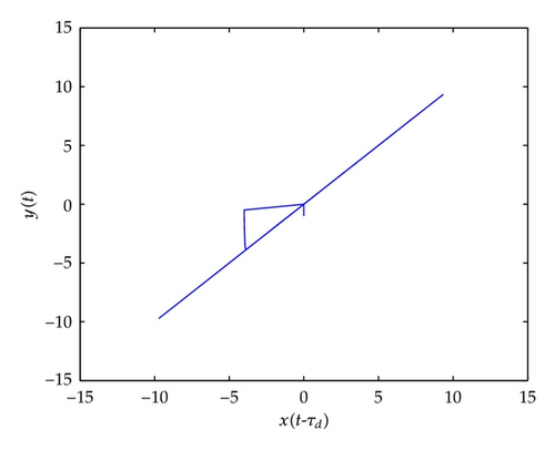
In Figure 1, the portrait of x(t − τd) versus y(t) illustrates that the lag synchronization of coupled partly nonidentical systems is established. However their trajectories do not remain in step with each other during a short part of evolution, because they are not in synchronization as t < τd.

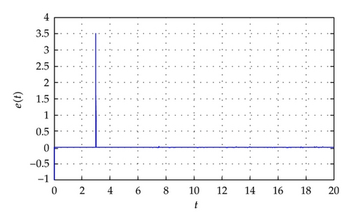
It is clear to observe from Figure 2 that synchronization error e(t) leaps at a sudden as τd = 3.0 and vanishes eventually in a short time. Then e(t) stays at zero.

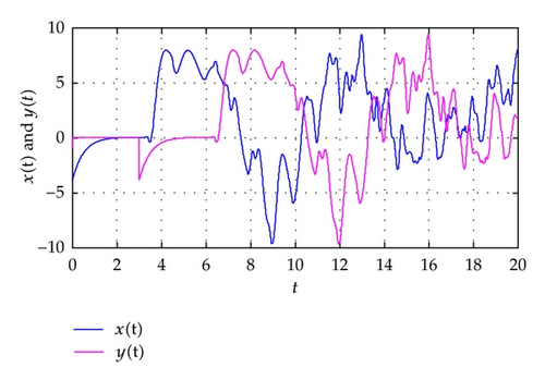
As shown in Figure 3, the slave′s state variable is retarded with the time length of τd = 3.0 in comparison with master′s. The desired lag synchronization is realized.

4. Conclusions
In this paper, we have presented a lag synchronization model as well as researched on it. Based on Lyapunov theory, the sufficient conditions of the synchronization model are given. Simulation results of the lag synchronization model are provided to illustrate the effectiveness and feasibility of the proposed method.
Acknowledgments
This work is supported by the National Natural Science Foundation of China (Grants nos. 61170269, 61121061), the Specialized Research Fund for the Doctoral Program of Higher Education (Grant no. 20100005110002) and the Fundamental Research Funds for the Central Universities (Grant no. BUPT2011RC0211).


