Dispersion of Love Waves in a Composite Layer Resting on Monoclinic Half-Space
Abstract
Dispersion of Love waves is studied in a fibre-reinforced layer resting on monoclinic half-space. The wave velocity equation has been obtained for a fiber-reinforced layer resting on monoclinic half space. Shear wave velocity ratio curve for Love waves has been shown graphically for fibre reinforced material layer resting on various monoclinic half-spaces. In a similar way, shear wave velocity ratio curve for Love waves has been plotted for an isotropic layer resting on various monoclinic half-spaces. From these curves, it has been observed that the curves are of similar type for a fibre reinforced layer resting on monoclinic half-spaces, and the shear wave velocity ratio ranges from 1.14 to 7.19, whereas for the case isotropic layer, this range varies from 1.0 to 2.19.
1. Introduction
Fiber-reinforced composite materials have become very attractive in many engineering applications recently due to their superiority over the structural materials in applications requiring high strength and stiffness in light-weight material. Consequently, the characterization of their mechanical behavior is an utmost requirement. The monoclinic system is the largest symmetry system with almost a third of all minerals belonging to one of its classes. This system contains two nonequal axes (a and b) that are perpendicular to each other and a third (c), that is, inclined with respect to the axes. The a and c axis lie in a plane. The a-c plane can be, but is not always, a mirror plane with left side of b-axis a reflection of the right side. Fledspar which is an example of monoclinic material is the name of a group of rock-forming minerals which make up as much as 60% of earth’s crust. Feldspars crystallize from magma in both intrusive and extrusive igneous rocks, and they also can occur as compact minerals, as veins, and are also present in many types of metamorphic rock. Rock formed entirely of plagioclase feldspar is known as an orthosite. Feldspars are also found in many types of sedimentary rock. The wave propagation in reinforced medium was studied by Chattopadhyay and Choudhury [1] and in crystalline monoclinic plate was studied by Chattopadhyay and Bandyopadhyay [2]. Propagation of elastic waves in laminated composite plates was studied by Datta et al. [3]. Chattopadhyay et al. [4] studied the propagation, reflection, and transmission of shear waves in monoclinic media and obtained a dispersion equation for a monoclinic layer overlying monoclinic half-space. Besides these, a large number of papers on elastic wave propagation have been published in different journals. Without going into details of research works in this field, we mention papers by Kim [5] and Nayfeh [6]. In this paper, we have computed the ranges of shear wave velocity ratio and the corresponding wave numbers for Love waves at a layer of fiber-reinforced material resting on monoclinic half-space and compared them with shear wave velocity ratio of Love waves at isotropic layer resting on monoclinic half-space. Using these values the dispersion curves have also been obtained.
2. Formulation of the Problem
3. Solution of the Problem
3.1. Boundary Conditions
4. Numerical Results and Discussion
The range of shear wave velocity ratio of Love wave has been obtained from (3.20), and within this range, the corresponding values of kh are obtained from (3.19) by considering different material constants of fiber-reinforced layer and monoclinic half-space. These values have been plotted to obtain the shear wave velocity ratio curve. We have obtained a set of shear wave velocity ratio curve for fiber-reinforced layer resting on half-spaces of different materials (monoclinic and isotropic). Similarly, a set of shear wave velocity curves for isotropic layer resting on monoclinic and isotropic half-spaces have also been obtained. These are specified in details in Cases 2 and 1, respectively, below.
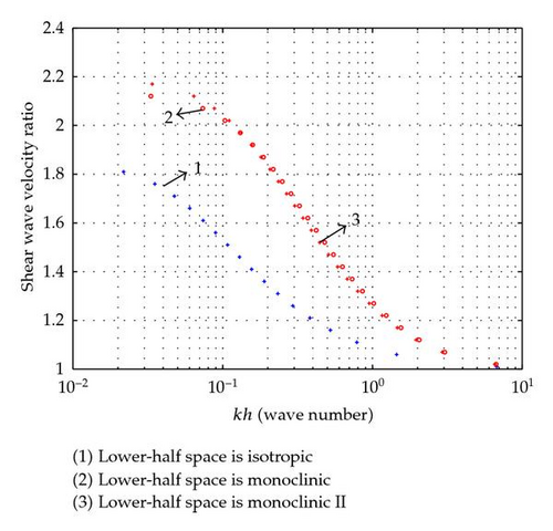
Case 1. Here we have considered three sets of arrangements; in all these, top layer is isotropic-I, and lower half-spaces are (i) isotropic-II with different material constants from isotropic-I, (ii) lower half-space is monoclinic, and (iii) lower half-space is monoclinic II, respectively. The material constants are = 6 × 10⁹ N/m2, ρ = 2300 kg/m3 for isotropic-I and μ = 25 × 109 N/m2, ρ = 2700 kg/m3 for isotropic-II. The material constants for monoclinic are as C55 = 0.94 × 10¹¹ N/m2, C56 = −0.11 × 10¹¹ N/m2, C66 = 0.93 × 10¹¹ N/m2, and ρ = 7800 kg/m3 and for monoclinic-II are C55 = 0.60 × 10¹¹ N/m2, C56 = 0.09 × 10¹¹ N/m2, C66 = 0.75 × 10¹¹ N/m2, ρ = 4700 kg/m3given by Tiersten [9]. Using these values, shear wave velocity ratio curves have been plotted for corresponding values of kh obtained from (3.19). The range of values for shear wave velocity ratio and kh are given in Table 1, and curves are given in Figure 1.
| Isotropic layer resting on half-space | Range of shear wave velocity ratio | Range of kh |
|---|---|---|
| Isotropic | 1.0–1.85 | Large value–0.00058 |
| Monoclinic | 1.0–2.1922 | Large value–0.013 |
| Monoclinic II | 1.0–2.1949 | Large value–0.06071 |

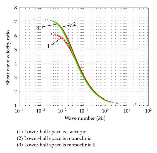
Case 2. In this case, we have plotted three dispersion curves as in Case 1. Here the upper layer is taken as fibre-reinforced layer, and the lower half-spaces are taken as in Case 1 of three separate arrangements, and the material constants are the same as earlier. The material constants for fibre-reinforced layer are μL = 2.45 × 10⁹ N/m2, μT = 1.89 × 10⁹ N/m2, and ρ = 7800 kg/m3. Shear wave velocity ratio curve for Love waves at fibre-reinforced layer has been plotted for all these three cases and shown in Figure 2, and the ranges of shear wave velocity ratio and wave number are shown in Table 2.
From the results it has been observed that shear wave velocity ratio for Love waves at fibre-reinforced layer is very much higher than at isotropic layer.
| Reinforced layer resting on half-space | Range of shear wave velocity ratio | Range of kh |
|---|---|---|
| Isotropic | 1.14–6.15 | Large value–0.0028 |
| Monoclinic | 1.14–7.16 | Large value–0.0125 |
| Monoclinic II | 1.14–7.19 | Large value–0.0110 |

5. Conclusions
From the curves plotted and results tabulated, it has been clearly observed that the shear wave velocity ratio for a fiber-reinforced layer resting on any layer whether it is isotropic or monoclinic is always much higher than on the isotropic layer resting on similar half-spaces. For the case of fiber-reinforced layer, shear wave velocity ratio ranges from 1.14 to 6.15, 1.14 to 7.16, and 1.14 to 7.19, for isotropic half-spaces, monoclinic and monoclinic-II half-spaces, respectively. In the contrary for the case of an isotropic layer, the shear wave velocity ratio ranges from 1.0 to 1.85, 1.0 to 2.19, and 1.0 to 2.19 for the case isotropic, monoclinic, and monoclinic-II half-spaces, respectively.
Acknowledgments
S. Saha is very much thankful to Director CRRI, for his permission to publish this paper. S. Saha is also very much thankful to the reviewer for valuable comments to modify this paper.


