Localized States in Bi-Pattern Systems
Abstract
We present a unifying description of localized states observed in systems with coexistence of two spatially periodic states, called bi-pattern systems. Localized states are pinned over an underlying lattice that is either a self-organized pattern spontaneously generated by the system itself, or a periodic grid created by a spatial forcing. We show that localized states are generic and require only the coexistence of two spatially periodic states. Experimentally, these states have been observed in a nonlinear optical system. At the onset of the spatial bifurcation, a forced one-dimensional amplitude equation is derived for the critical modes, which accounts for the appearance of localized states. By numerical simulations, we show that localized structures persist on two-dimensional systems and exhibit different shapes depending on the symmetry of the supporting patterns.
1. Introduction
Spatial patterns appear spontaneously in out-of-equilibrium systems and are observed in many different physical contexts [1]. During the last two decades, spatial pattern formation has been largely studied, leading to the identification of various types of spatiotemporal instabilities and symmetry selection processes in the general frameworks of dynamical systems and bifurcation theory [2, 3]. Localized structures, that is, patterns extended over a restricted spatial domain, have received, in particular, a large interest, and from the early observations of magnetic domains in ferromagnetic materials [4], localized states have been successively observed in such different systems as liquid crystals [5], plasmas [6], chemical reactions [7], fluid surface waves [8], granular media [9, 10], and thermal convection [11, 12]. In nonlinear optics localized structures were first predicted as solitary waves in bistable optical cavities [13], and successively also explained in terms of diffractive auto-solitons [14]. Optical localized structures attract nowadays a lot of interest since they are potential candidates for optical memories [15].
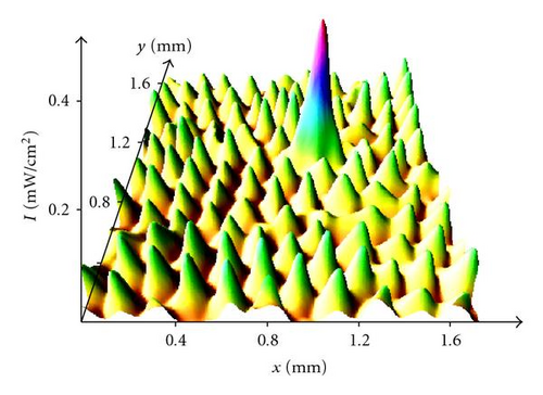
In one-dimensional systems, localized structures or localized patterns can be described as homoclinic orbits passing close to a spatially oscillatory state [1, 16], or to the ghost of a spatial pattern [17, 18], and converging to an homogeneous state, whereas domains are seen as heteroclinic trajectories joining the fixed points of the corresponding dynamical system [19]. Recently, in a nematic liquid crystal light valve with optical feedback it has been found experimentally a different type of localized states, appearing as large amplitude peaks nucleating over a lower amplitude pattern, therefore called localized peaks [20]. Figure 1 shows the typical localized peak observed in the light valve with optical feedback. More recently, similar observations have been numerically reported in other optical systems, such as in atomic vapors with optical feedback [21] and in intracavity photonic crystals [22]. Moreover, localized peaks appear also in a Newtonian fluid, when nonlinear surface waves are parametrically excited with two frequencies [23], and in monoatomic layer deposition [24]. Thus, these examples of localized states appearing over a patterned background [20–24] seem to constitute a different universal class of structures with respect to the localized states that rise up from an uniform background [1, 4–9, 11–13, 16, 19].
The interplay of localized states with a structured background is particularly interesting in nonlinear optics, where it opens interesting technical issues on the control of localized structures, with the possibility of driving their dynamics and tailoring their interactions [25–28]. Here, we present a general description of bi-pattern systems, by which we mean systems that exhibit coexistence between two distinct pattern states and are, therefore, able to generate localized peaks. In these systems, localized structures are pinned over an underlying spatial grid, which can be either spontaneously created by a self-organized pattern formation or externally induced by a spatial periodic forcing. We show that in both cases the observed dynamical behaviors are qualitatively the same. However, while the features of the spontaneous pattern formation are difficult to control, the external forcing has the advantage of providing an easy and precise way to determine the features of localized structures, as well as to allow a direct comparison with the theoretical developments.
On the basis of amplitude equations, a first preliminary one-dimensional description of localized states observed in bi-pattern systems was done by the present authors in a recent Letter [29]. The aim of the present article is to study and characterize the universal mechanism that is at the origin of localized states pinned over an underlying lattice. In order to derive an unifying and simple description of localized peaks, we develop a theoretical model for one-dimensional spatially extended systems close to a spatial bifurcation. The model, which describes coexistence of two different patterns and stable front solutions between them, is based on an amplitude equation that includes a spatial parametric forcing. This extension with respect to conventional amplitude equations, allows to describe localized patterns and to account for the main properties of these solutions. The model includes the interaction of the slowly varying envelope with the small scale of the underlying pattern [30], well-known as the nonadiabatic effect [31, 32].
As examples of bi-pattern systems in two-dimensions, we consider: a liquid crystal light valve (LCLV) with optical feedback, which provides our experimental framework, and a spatially forced subcritical pitchfork as a prototype model. Both systems show robust existence of localized states, which exhibit different shapes depending on the symmetry of the supporting patterns.
The paper is organized as follows. In Section 2 we present the two example systems, namely the experiment of the LCLV with optical feedback, and the forced subcritical pitchfork model, showing the typical localized states appearing in both systems. Section 3 contains the unified one-dimensional description of bi-pattern systems, which relies on the derivation of an amplitude equation amended by the inclusion of nonadiabatic terms, and Section 4 are the conclusions.
2. Examples of Localized States in Bi-Pattern Systems
To provide inspiration of localized states in bi-pattern systems, we shall consider a liquid crystal valve with optical feedback as an experiment and numerical simulations of a spatially forced subcritical pitchfork as a prototype model. In the experiment, the underlying lattice of the bi-pattern is realized either by letting the systems to spontaneously generate a self-organized pattern, or by imposing an intensity grid through a spatial periodic forcing. This last case compares directly with the model, which is indeed a spatially forced amplitude equation.
2.1. Experimental Evidence of Localized Peaks
The experimental setup, consisting of a LCLV in an optical feedback loop, is the same as the one reported in [33]. The LCLV is composed of a nematic liquid crystal film inserted in between a glass and a photoconductive plate over which a dielectric mirror is deposed. The liquid crystal film is planar aligned (nematic director parallel to the walls), with a thickness d = 15 μm. Transparent electrodes deposited over the glass plates permit the application of an external voltage V0 across the liquid crystal layer. The photoconductor behaves like a variable resistance, which decreases for increasing illumination. The feedback is obtained by sending back onto the photoconductor the light which has passed through the liquid-crystal layer and has been reflected by the dielectric mirror. The light beam experiences a phase shift which depends on the liquid crystal reorientation and, on its turn, modulates the effective voltage that locally applies to the liquid crystals.
The feedback loop is closed by an optical fiber bundle and is designed in such a way that diffraction and polarization interference are simultaneously present [33]. The presence of diffraction leads to the spontaneous generation of self-organized patterns, which display a typical spatial period scaling as , where λ is the laser wavelength and L is the optical free propagation length in the feedback loop [34]. On the other hand, the presence of polarization interference leads to bistability between different spatial states. Setting L = 0 eliminates diffraction effects, so that in this case the system exhibits bistability between homogeneous states.
As a first set of experiment, we fix L = −40 mm, so that the system spontaneously selects the lattices contributing to the bi-pattern interplay. The voltage applied to the LCLV has a rms value of V0 = 12.3 V, with a frequency 6 kHz. Note that the period of the sinusoidal voltage V0 is much shorter than the liquid crystal response time and of the typical times for electroconvection [35], thus, liquid crystals are sensitive only to the rms value of the applied voltage and perform a static reorientation. Hydrodynamical effects, such as backflow, are avoided and the molecular realignment is a pure Fréedericksz transition [36].
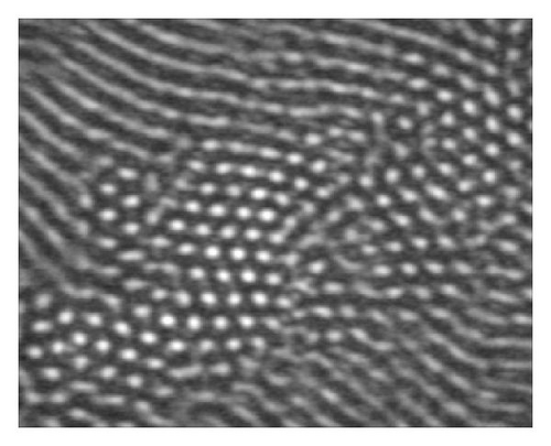
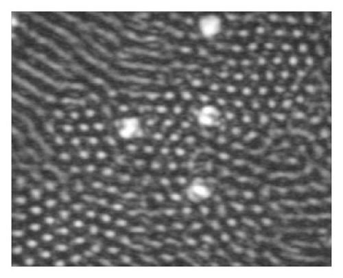
By increasing the input light intensity Iin we observe a sequence of transitions, as shown by the experimental snapshots of Figure 2. First, the homogeneous steady-state looses stability and develops a pattern of hexagons (Figure 2(a)). By further increasing Iin, localized peaks of higher amplitude appear over the hexagonal background (cf. Figures 1 and 2(b)). For higher values of Iin the system exhibits a novel pattern state, which has a small coexistence region with the hexagonal pattern [20]. Figure 2(c) shows the pattern state observed for high Iin.

The theoretical model for the LCLV feedback system was previously derived in [37] and consists in two coupled equations, one for the average director tilt , 0 ≤ θ ≤ π/2, and one for the feedback light intensity Iw. The equation for the director reads as
where l is the electric coherence length, τ the local relaxation time and f(θ) a function taking into account the response of the photoconductor to the feedback intensity Iw: f(θ) = 0 when V ≤ ΓVFT and when V > ΓVFT, with V the voltage that effectively applies to the liquid crystals
and VFT the threshold voltage for the Fréedericksz transition. Γ is the impedance of the LCLV dielectric layers and α a phenomenological parameter summarizing, in the linear approximation, the response of the photoconductor. After a free propagation length L, the feedback light intensity is given by
the diffraction being accounted for by the operator . Similar relationships between the tilt angle and the optical intensity distribution have been previously derived for light diffraction in electroconvective liquid crystal cells, where far-field diffraction [38] or shadowgraph methods [39] were employed for pattern visualization, but without any feedback of light onto the tilt angle. Recently, electro-hydrodynamic convection in a nematic liquid crystal cell with a photoconductive electrode has been reported [40]. In such a case, though there was no feedback, the light beam was acting as an external photocontrol, locally modifying the voltage applied to the liquid crystal.
We have performed numerical simulations of our model equations (1), (2), and (3) by taking as values of the parameters Γ = 0.15, α = 5.5 Vcm2/mW, VFT = 3.0 V, l = 30 μm, λ = 632 nm, L = −40 mm. In Figure 3 is displayed a numerical intensity profile showing a localized peak over a hexagonal pattern. By comparing with Figures 1 and 2, we can see that the numerical profile is in a fairly good agreement with the experimental profile and snapshot for the light intensity.
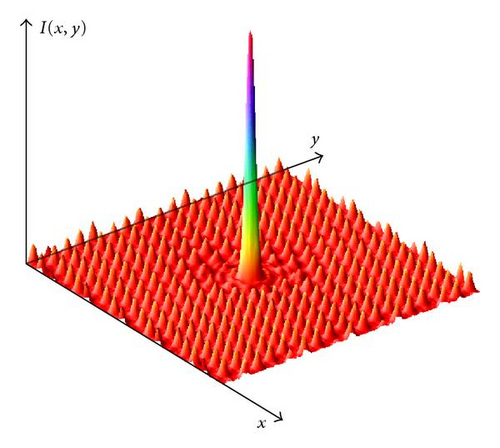
In brief, it exists a large range of parameters within which the LCLV with optical feedback spontaneously is a bi-pattern system, exhibiting localized states pinned over a self-organized lattice generated by the system itself.
2.2. Spatially Forced Subcritical Pitchfork Model
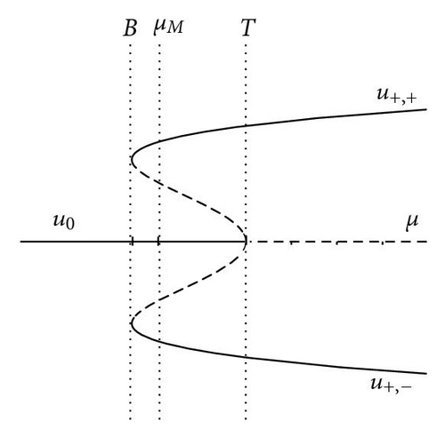
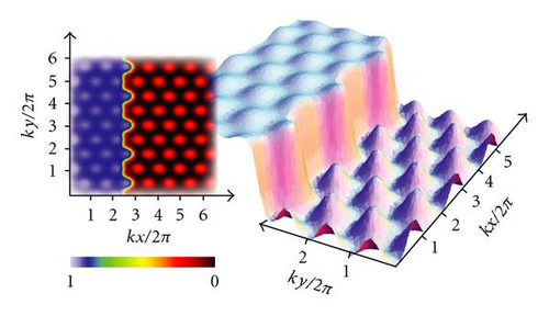
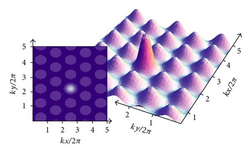
Hence, in the bi-pattern region we observe front solutions and localized states between the two patterns. As a consequence of the interplay between the envelope variations and the wave number of the underlying pattern, the front solutions are motionless in a region of parameters, so-called the pinning range. Close to this region we expect to observe a family of localized states [30, 31]. Figure 6 illustrates a typical localized state observed in the hexagonally forced model (6), that appears as a localized peak over a structured background. In the experiment of the LCLV with feedback, it has been recently shown that the effect of a hexagonal spatial forcing induces regular arrays of localized structures [26].
2.3. Spatially Forced Experiment: Bi-Patterns and Localized States
Recently, we have shown in the LCLV experiment that a spatially periodic grid can be imposed, by means of a spatial light modulator, on the profile of the input beam [26]. In such a case, localized structures are pinned over the grid, which controls their dynamical behavior. Here, we have set to zero the free propagation length in the feedback loop, that is, L = 0, hence no spatial scale is spontaneously selected by the system itself. Then, by using the previous technique, we have imposed on the input beam a spatial grid of the desired symmetry and period. In doing so, we are strongly motivated by the possibility of establishing a direct comparison with the above model, (6) or (8).
We have imposed on the system either a hexagonal or a square intensity grid. For both grids, the input intensity is 1.1 mW/cm2 with an amplitude modulation of approximately 10%. For the square grid, the spatial period is set to 130 μm whereas for the hexagonal grid it is 150 μm. The voltage applied to the LCLV is slightly changed around V0 = 5.5 V, with a fixed frequency of 5 kHz. For this values of parameters the system is bistable and, being spatially forced by the intensity grid, it displays bi-patterns an localized states. By setting a specific initial condition, we can select either to induce an interface between the two patterns or to create localized peaks.
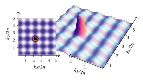
As examples of bi-patterns, we show in Figures 8(a) and 8(b) the interface between a high and a low amplitude pattern obtained with (a) a square and (b) a hexagonal grid, respectively. For the same grids, but changing the initial conditions, we can easily induce localized peaks. An example of localized peak is shown in Figure 9 for a square grid.
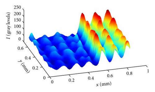
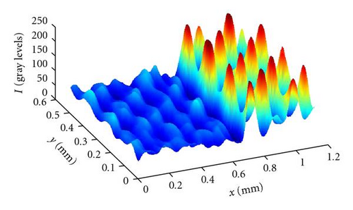
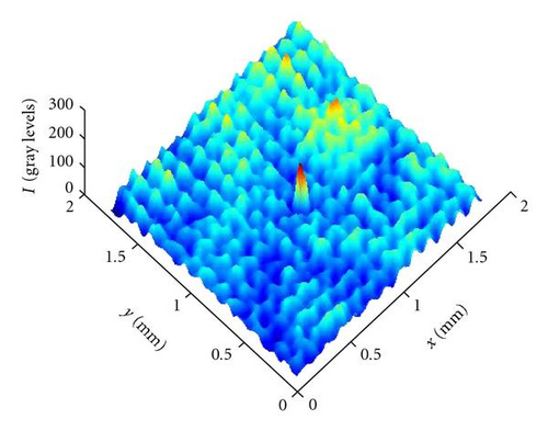
We can notice a good qualitative agreement between the experimental profiles and those obtained by numerical simulation of the spatially forced models (6) and (7), for a hexagonal and a square forcing, respectively. Moreover, the qualitative behavior of the spatially forced systems, both the experiment and the model, is very similar to the one displayed, in a certain range of parameters, by the unforced system with diffraction playing the role of forcing. Indeed, in the region of parameters where the unforced system displays localized peaks, the qualitative dynamical features are very closely the same as those displayed by the forced systems. However, when the input intensity is increased, the unforced system shows a transition to a spatiotemporal chaotic state, which is not the case for the spatially forced system.
In conclusion, localized states in bi-pattern systems are robust phenomena and appear naturally when bistability is accompanied by a mechanism of spatial periodic forcing. This can be either externally imposed, or generated by the system itself in a certain range of parameters. In the next section we will present an unified description of localized states in one-dimensional bi-pattern systems.
3. Unified Description
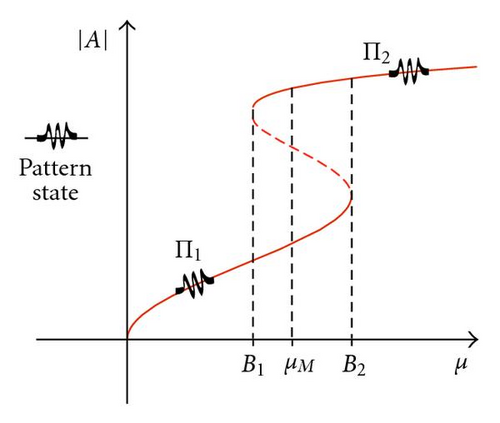
As depicted in Figure 10, for a given range of parameter values the system shows coexistence between two different spatially periodic states, each one corresponding to a homogeneous state for the amplitude equation. Thus, it is a bi-pattern system. The coexistence region is B1 < μ < B2. The extended stationary solution of the amplitude equation (10), has the form A = R(x)eiθ(x), where R(x) and θ(x) are the envelope modulus and phase, respectively. These functions satisfy the relation θ(x) = ∫ ϵ/R(x) 2dx. For uniform modulus solution (Ro), one has the expression for the envelope
3.1. Amended Amplitude Equation
In order to take into account the nonadiabatic effect, we compute the corrections of the amplitude equation by including the nonresonant terms, that is, the solvability condition for the amplitude A has the form
In order to obtain the change of the front interaction as a result of the spatial forcing, we consider the front solution of the resonant equation
where R±(x − xo) satisfies
xo is the position of the front core and the lower index + (−) corresponds to a front monotonically rising (decreasing). As the nonresonant term is a rapid spatial oscillation, we consider this term as perturbative-type and use the Anstaz
in (18), where , and {δW, δφ} are small functions, and Ro,± are the stable equilibrium states of the resonant amplitude equation (10) and Ro,+ > Ro,−. After straightforward calculations, we obtain the following solvability condition for the δW function (front interaction law)
with
where
and .
As a consequence of the spatial forcing the front interaction law close to the pinning range, (22), has an extra term and now alternates between attractive and repulsive forces. It is important to remark that is a parameter exponentially small, proportional to η, and is of order δ, that is, the source of the periodical force is the spatial forcing in the (18). Therefore, close to the Maxwell point the system exhibits a family of equilibrium points, dΔ/dt = 0. Each equilibrium point correspond to a localized solution nucleating over a pattern state. These solutions correspond to localized patterns. The lengths of localized patterns are multiple of a basic length, corresponding to the shortest localized state. These shortest states are the localized-peaks, corresponding to the experimental observations reported in [20]. In Figure 11, it is depicted the front interaction law and the family of equilibrium points.
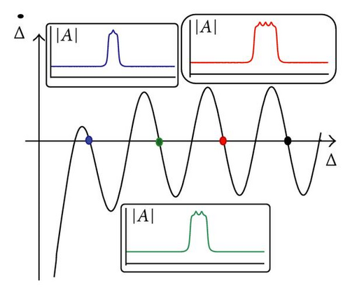
Due to the oscillatory nature of the front interaction, which alternates between attractive and repulsive forces (cf. Figure 11), we can deduce the dynamical evolution and bifurcation diagram of localized patterns. By decreasing δ or increasing η, the family of localized patterns disappears by successive saddle-node bifurcations and only localized peaks survive.
4. Conclusions
Bi-pattern systems are spatially extended systems that display coexistence of two pattern states. They exhibit a rich variety of localized solutions, in particular, localized peaks are pinned over a spatial grid, that can be either spontaneously generated by the system itself, or externally imposed. These localized states are of particular interest in nonlinear optics, where they constitute the elementary pixels of optical memories. The interplay with a structured background open new technical perspectives on the control of their dynamics. We have derived an unified and simple description of localized peaks in one-dimensional spatially extended systems close to a spatial bifurcation. This model allows us to understand the mechanism underlying the formation of localized states, which is based on the coupling between the spatial variations of the envelope and the wavelength of the background pattern. In two-dimensions, we show that these localized states persist and exhibit different shapes depending on the symmetry of the supporting patterns. However, a natural extension of the front interaction law, for instance an interface tension, is not yet available. Work in this direction is in progress.
Acknowledgments
The simulation software DimX , developed at INLN, has been used for all the numerical simulations presented in this paper. The second author acknowledges the financial support of FONDECYT Project 1090045, and FONDAP Grant 11980002. The third author thanks the financial support FONDECYT Project 11080286. The first and the fourth authors thank the financial support of the ANR-07-BLAN-0246-03, turbonde.


