On the Flow Behavior in Rotor-Stator System with Superposed Flow
Abstract
The flow between a rotor and a stator at high Reynolds number and small Ekman number is divided into three domains, two boundary layers adjacent to the discs separated by a central core. In the present work, a simple theoretical approach provides analytical solutions for the radial distribution of the core swirl ratio valid for a rotor-stator system with a superposed radial inflow rate. At first, the flow in the rotor boundary layer is assumed to behave as expressed by Owen and Rogers (1989) in the case of a turbulent flow on a rotating single disc. On the stator side, a necessary compensation flow rate must take place according to the conservation of mass. It is found that this compensation flow rate cannot be estimated with a good accuracy using the hypotheses of a stationary disc in a rotating fluid by Owen and Rogers (1989). Thus, two innovative weighting functions are tested, leading to new analytical laws relating the core swirl ratio K to the coefficient of flow rate Cqr introduced by Poncet et al. (2005). The adequacy between the theoretical solutions and numerous results of the literature is clearly improved and the discussion allows a better understanding of the flow behavior.
1. Introduction
Problems involving flows between rotating discs could be representative of a lot of situations often encountered in turbomachinery, such as cooling system of modern gas turbines, pumps, water and steam turbines, and so forth. A detailed review of many recent studies is reported in Owen and Rogers [1].
The earlier studies are proposed by von Karman [2] who simplified the equations of motion to nonlinear differential equations by means of axial symmetry hypothesis for the infinite disc rotating in a quiescent fluid and by Bödewadt [3] who focused on a stationary disc in vicinity of a rotating fluid. Batchelor [4] gathered the two problems in the case of a rotor-stator system and proposed a model based on the presence of two boundary layers adjacent to the discs, and separated by a central core rotating as a solid body. This result has been contrasted by Stewartson [5] who modeled the presence of one boundary layer (the rotor one). Both solutions have been experimented for different cavity aspect ratios and Reynolds numbers.
A lot of numerical and experimental studies dealing with enclosed rotor-stator systems can be found in the literature. Daily and Nece [6] individuated four flow regimes corresponding to laminar or turbulent flow with merged or “separated” boundary layers. Itoh et al. [7] studied the effect of the rotational Reynolds number on the mean velocity field for shrouded discs. It is worth pointing out that, from their studies, the region near the rotating axis remains laminar even for a high rotational rate. Furthermore, the transition from laminar to turbulent regions occurs first along the stator side and then laminar and turbulent flows coexist. Other numerous works dealing with the flow in enclosed systems can be quoted: Stepanoff [8], Szeri et al. [9], Dijkstra and van Heijst [10], Cheah et al. [11], and more recently Randriamampianina et al. [12]. Of course, influence of external flow and peripheral geometry of the cavity is not considered.
In case of a rotor-stator cavity, finite and open at the periphery, peripheral and external conditions are very important. Djaoui et al. [13] and more recently D′Haudt et al. [14] and Debuchy et al. [15] highlighted the strong influence of the geometrical dimensionless parameter λ defined by the ratio of the difference between stator and rotor radii and the axial gap of the cavity, in the case of an isolated system, that is, without any superposed inflow. The case of a rotor-stator system with a superposed centripetal inflow has been investigated by Debuchy et al. [16]. For high Reynolds number, small gap ratio and small Ekman number, it was found that the flow structure is strongly modified as soon as a very weak inflow is applied, enhancing the level of the core swirl ratio near the axis. Poncet et al. [17, 18] have found an analytical law for the radial distribution of the central core swirl ratio, in very good agreement with numerous experimental and numerical results.
In the present work, a simplified theoretical approach leads to analytical solutions for the core swirl ratio in case of a rotor-stator system with superposed inflow. Starting from results of Owen and Rogers [1], the fluid centrifuged by the rotor wall is assumed to behave as a turbulent flow on a single disc. On the other side (rotor side), it is shown that the compensation flow rate cannot be estimated with a good accuracy using the results of Owen and Rogers [1] in case of a stationary disc in a rotating fluid because a radial circulation of fluid also takes place in the central core. Thus, the authors have tested innovative weighting functions leading to new analytical laws relating the core swirl ratio K to the coefficient of flow rate Cqr introduced by Poncet [17]. In the discussion, extensive comparisons with experimental and numerical results are in a very good agreement and provide a better comprehension of the flow behavior.
2. Theoretical Approach
The flow takes place between a rotor of radius R, rotating with an angular velocity Ω, and a stationary disc. The axial distance between the two discs is H (Figure 1). The flow is assumed to be incompressible, steady, and axisymmetric. r and z are, respectively, the radial and axial coordinates (r = 0 at the axis, z = 0 on the rotor).
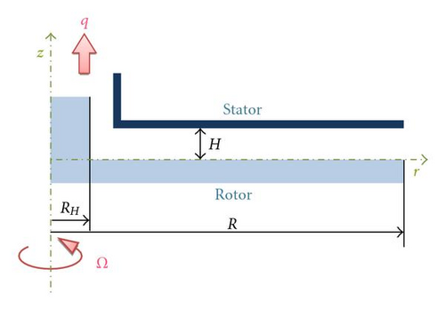
In the present work, the authors assume that the order of magnitude of the radial velocity component U0 is , RH being the radius of the central hub. This hub which exists in the real machineries allows to avoid the singularity at r = 0.
The adequacy between relations (14), (15), (17), and (18), and numerous theoretical, experimental, and numerical results of the literature will be discussed in the following section.
3. Results and Discussion
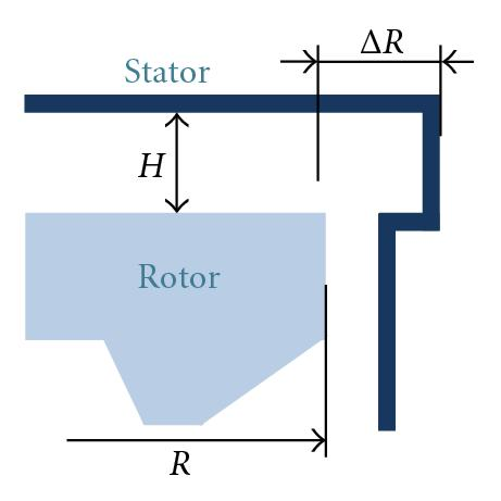
The validity of the theory is now discussed by making comparisons with the experimental results of Debuchy [19], Debuchy et al. [16], and also with the theoretical, numerical, and experimental works of Poncet [17], Poncet et al. [18, 20]. All results have been obtained in an annular cavity between a rotating disk equipped with a central hub and a stationary disk with a central outlet section in order to ensure a superposed flow. The two experimental setups have already been detailed in Debuchy [19] and Poncet [17]. The most significant differences are located at the periphery of the two systems, with the consequence that it may influence the inlet flow properties. It has been shown by Debuchy et al. [15] that if the inlet flow comes from the external fluid at rest, then the peripheral core swirl ratio (i.e., the preswirl level) is weak, otherwise the preswirl will be higher. Consequently the authors are more interested in the description of the peripheral geometry of the two cavities (Figures 2(a) and 2(b)).
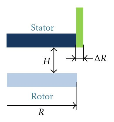
The apparatus used by Debuchy [19] was totally open at the periphery. The rotor, 750 mm in diameter, was rotating at 1500 rev/min and equipped with a central hub, 180 mm in diameter. The axial gap of the cavity was fixed to 30 mm which means that the gap ratio was 0.08. A stationary shroud, 8 mm in thickness, covered the axial upper side of the stator, which made the stator radius larger than that of the rotor. Consequently, the λ parameter introduced by Debuchy et al. [15] was fixed to 0.27. Measurements were performed in air at Reynolds number fixed to 1.47 × 10⁶ (i.e., Ekman number fixed to 1.06 × 10⁻⁴ ).
In the rotor-stator system used by Poncet, an external stationary shroud near the periphery forced the fluid to recirculate near the rotor with the consequence that the preswirl level is high. The rotor, 500 mm in diameter, was rotating up to 600 rev/min. The axial gap of the cavity was adjustable between 1 and 12 mm. Measurements were performed in water using a laser doppler anemometry.
The main characteristics and dimensionless parameter values retained for the discussion section are listed in Table 1. In all cases, the conditions (2) are always verified. The values of λ parameter are to a large extent identical in the two experimental setups. In test case A, RoH is much lower than 1, on the contrary to test cases B and C. However, is always lower than 1 ( is the maximum value for the test case C), which means that relation (11) is valid and that the solutions (14), (15), (17), and (18) are to be tested.
| Debuchy [19] | Poncet [17] | ||
|---|---|---|---|
| Test case A | Test case B | Test case C | |
| R | 375 mm | 250 mm | |
| H | 30 mm | 9 mm | |
| ΔR | 8 mm | 3 mm | |
| η | 0.24 | 0.15 | |
| λ | 0.27 | 0.33 | |
| G | 0.08 | 0.036 | |
| Re | 1.47 × 10⁶ | 10 6 | |
| Ek | 1.06 × 10⁻⁴ | 7.7 × 10⁻⁴ | |
| RoH | 6.95 × 10⁻² | 17.4 × 10⁻² | 29.2 × 10⁻² |
| Cw | 11 886 | 5 929 | 9 881 |
| Air | Water | ||
| Hot wire anemometry | Laser doppler anemometry | ||
| LDA | |||
In the first part of the discussion, the authors evaluate the order of magnitude of the terms neglected in relation (11) by comparison to (6a), that is, the order of magnitude of with regard to . The quantity ε is used to define the ratio .
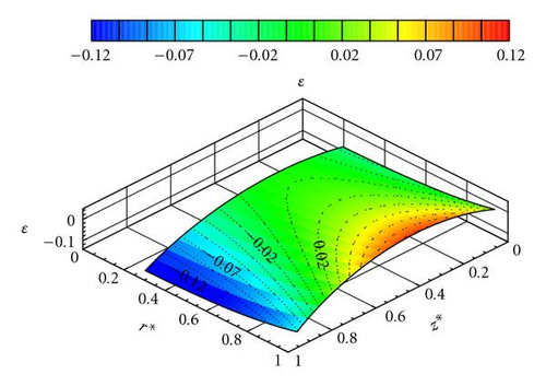
The experimental results of test case A have already been compared to solution (7) with values of b, c, α and β adjusted with the experimental results of Debuchy et al. [16]. The ratio ε is computed from relation (7) with b = 0.175, c = 0.04, α = 0.3, and β = 0.09. The obtained results are plotted in Figure 3 versus r* and z* for 0.24 ≤ r* ≤ 1.0 and 0.05 ≤ z* ≤ 0.95. Boundary layers have not been considered because the theoretical solution is valid only in the central core: viscous terms in the right-hand of relation (6a), (6b), and (6c) have been eliminated, so that the no-slip conditions at z* = 0 and z* = 1, at z* = 0, and at z* = 1 were not satisfied in the theoretical solution. As shown in Figure 3, the absolute value of the ratio ε is always below 13%, the maximum being located on the stator side for the smallest value of r*.
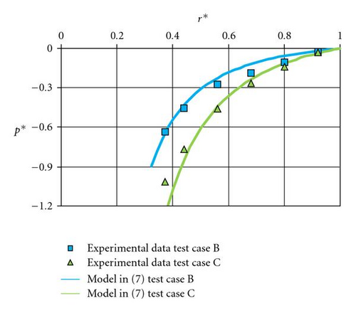
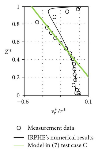
For test cases B and C, which have not yet been compared to solution (7), constants b and c have been adjusted firstly starting from the dimensionless pressure radial distribution (Figure 4). The authors mention that the dimensionless pressure p* is a little bit shifted in order to satisfy the condition p* = 0 at r* = 1 instead of the condition {p* − p*(r* = 0.92) = 0} chosen by Poncet et al. [18]. In a second step, the constants α and β are adjusted from the radial and tangential velocity profiles (Figure 5). The obtained values are mentioned in Table 2. For test cases B and C, the constants adjustment is very difficult because the authors only have few experimental results. However, the tangential velocity levels (Figures 5(a) and 5(b)) and the centripetal flow tendency for the radial velocity profiles at r* = 0.56 (Figures 5(c) and 5(d)) are in good agreement with the theoretical solution.
| b | c | α | β | |
|---|---|---|---|---|
| Test case B | 0.32 | 0.04 | 0.25 | 0.82 |
| Test case C | 0.45 | 0.04 | 0.25 | 0.93 |
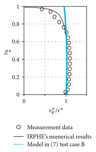
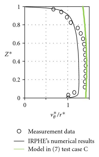
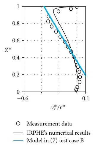
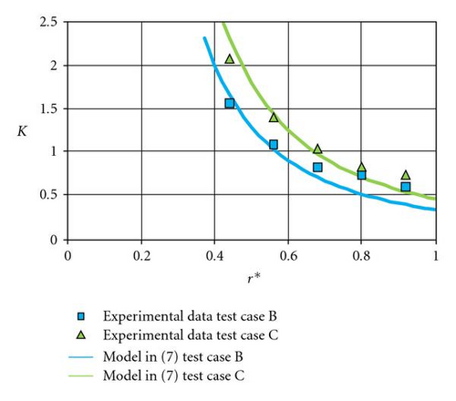
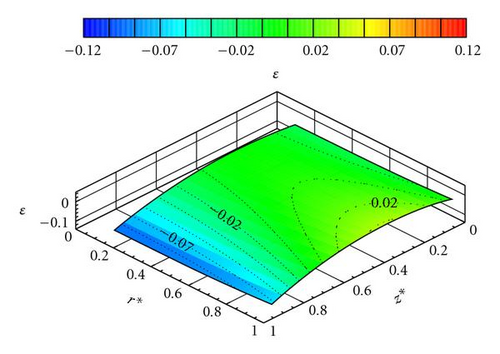
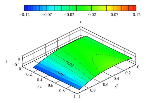
Using the adjusted constants in Table 2, the authors have found a good agreement for the radial distributions of the core swirl ratio, except the peripheral zone where the theoretical preswirl level is slightly underestimated. As for test case A, the radial and axial evolution of the ε ratio is plotted for 0.15 ≤ r* ≤ 1.0 and 0.05 ≤ z* ≤ 0.95 (Figures 7 and 8). It is found again that this ratio is below 13%.
The conclusion of the first part of the discussion is that the simplified radial momentum equation (11) can be used instead of relation (6a) since the ratio ε is small. The Rossby number defined in relation (9) is a significant parameter because ε is small for . The analytical solutions (14), (15), (17), and (18) in the theoretical part, based on (9) and (11) can be tested in the following part of this discussion.
To begin, the validity of the hypothesis (13) which leads to the solutions (14) or (15) is tested. For this purpose, comparisons between the theoretical solution (15) and results extracted from Poncet et al. [18] are presented in Figure 9. Poncet et al. [18] have found a very good agreement between their analytical law and numerous experimental results (with the adjusted values a ≈ 5.9 and b ≈ 0.63) and also with numerical results based on RSM model (with an adjusted value of a slightly lower: a ≈ 5.3).
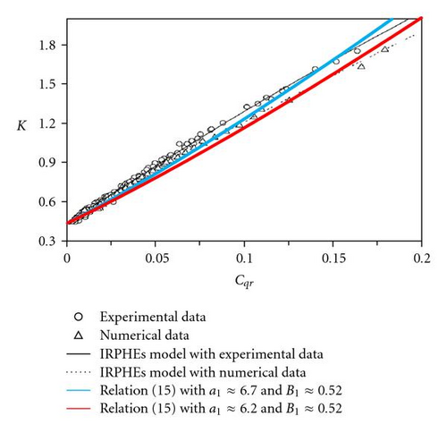
Testing relation (15), the best results were obtained for a1 ≈ 6.7 and B1 ≈ 0.52 in the case of experiments and a1 ≈ 6.2 and B1 ≈ 0.52 for numerical results. However, the authors found that the agreement is to be improved. The last remark had led the authors to insert a weighting function in (16) and to test relations (17) and (18).
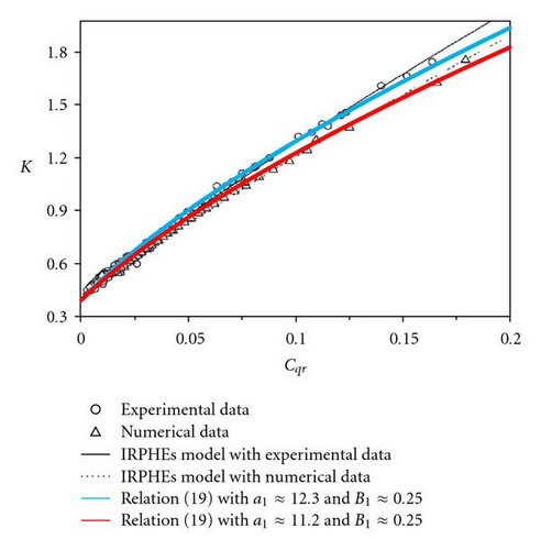
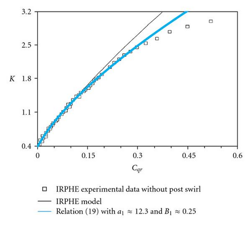
The second relation in (19) is validated using the experimental and numerical results from Poncet et al. [18] after adjustment of constants a1 and B1 (a1 ≈ 12.3 and B1 ≈ 0.25 for comparison with experiments; a1 ≈ 11.2 and B1 ≈ 0.25 for comparison with numerical results). The agreement is much better than that obtained with relation (15), at least for Cqr ≤ 0.2 (Figure 10).
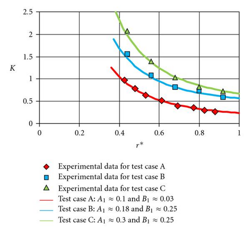
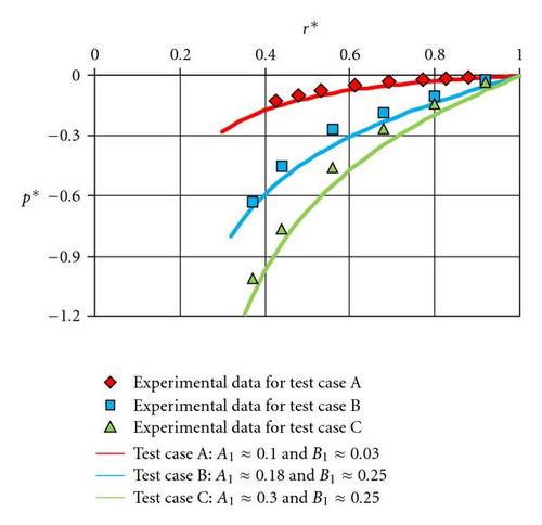
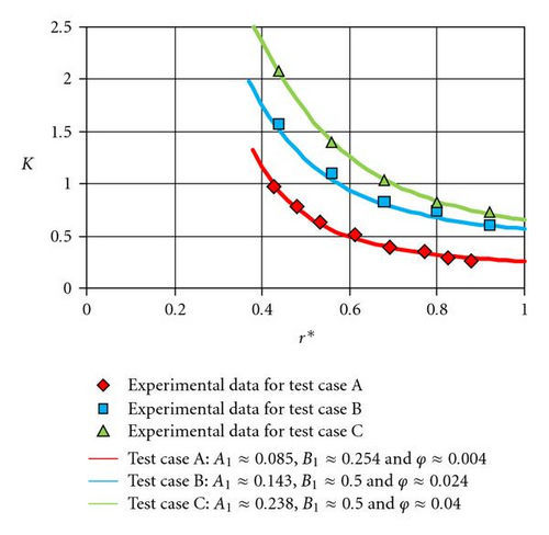
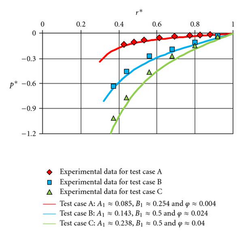
The first relation in (19) giving the radial distribution of the core swirl ratio is validated using the experimental results of test cases A, B, and C. A very good agreement has been found with A1 ≈ 0.1 and B1 ≈ 0.03 for test case A, A1 ≈ 0.18 and B1 ≈ 0.25 for test case B, and A1 ≈ 0.30 and B1 ≈ 0.25 for test case C for both the core swirl ratio (Figure 11) and the dimensionless pressure (Figure 12) distributions.
As c = 3/2, the weighting function introduced in (16) is K7/10, which is found to be close to the weighting function K1/2 mentioned in the theoretical approach in case of laminar boundary layer.
Large discrepancies are observed in the core swirl ratio distribution for Cqr ≥ 0.35 whereas the analytical solution from Poncet [17] is valid for values of Cqr below 0.2 as shown in Figure 13. This may be improved with a weighting function of Cqr in (16), as previously discussed, or with a more realistic hypothesis concerning the rotor boundary layer. Indeed, it is well known that the rotor flow rate is centripetal for core swirl ratio upper than 1: this behavior is not taken into account in hypothesis (13).
Comparisons between the theoretical law (20) and the experimental data corresponding to test case A (with A1 ≈ 0.085, B1 ≈ 0.254, and ϕ ≈ 0.004), test case B (with A1 ≈ 0.143, B1 ≈ 0.500, and ϕ ≈ 0.024), and test case C (with A1 ≈ 0.238, B1 ≈ 0.500, and ϕ ≈ 0.04) are shown in Figures 14 and 15. The results are in very good agreement.
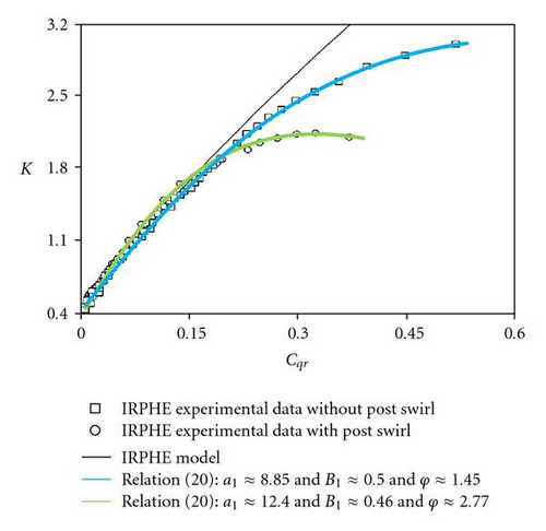
Finally, the validity of the second equation of (20) has been tested over the complete positive range of Cqr. Taking Figure 13 as a reference, one additional configuration has been considered: it consists of the rotor-stator system in Figure 2(b) with a central hub generating another value of post-swirl (i.e., the central core swirl ratio near the hub). Of sure, the constants in the analytical law need to be adjusted for each configuration. An excellent agreement between theory and experiments is shown in Figure 16 for Cqr values up to “0.6.”
4. Conclusion
The aim of this work was to propose a simple theoretical approach in order to obtain a new law relating the core swirl ratio K to the dimensionless flow coefficient Cqr in a rotor-stator system with superposed flow. Starting from the published results of Owen and Rogers, the authors assumed that the fluid on the rotor side behaves as a turbulent flow on a rotating single disc. It is shown that the compensation flow rate on the stator side cannot be described when using the hypothesis of a stationary wall in a rotating fluid by Owen and Rogers but that an innovative weighting function is to be introduced. At first, testing a weighting function with the form of W = Kc is interesting because it leads to well-known solutions of the literature. The adequacy between theory and numerous published data is good for a limited range of the coefficient of flow rate. This result is clearly improved with a weighting function with the form of . It leads to a new explicit analytical solution for K valid over a wide range of the Cqr coefficient, knowing that the radial distribution of the core swirl ratio is an interesting quantity for turbomachinery applications.
Nomenclature
-
- Cw:
-
- Dimensionless flow rate = q/υR
-
- Cqr:
-
- Coefficient of flow rate
-
- Ek:
-
- Ekman number
-
- G:
-
- Gap ratio = H/R
-
- H:
-
- Axial gap of the cavity
-
- K:
-
- Core swirl ratio at z* = 1/2
-
- p:
-
- Static pressure on the stator
-
- p*:
-
- Dimensionless static pressure on the stator = (p − patm)/((1/2)ρΩ2R2)
-
- patm:
-
- Atmospheric pressure
-
- q:
-
- Superposed volume flow rate
-
- q*:
-
- Local dimensionless flow rate = q/υr
-
- r:
-
- Radial coordinate
-
- r*:
-
- Dimensionless radial distance = r/R
-
- R:
-
- Outer radius of the rotor
-
- RH:
-
- Outer radius of the hub
-
- Re:
-
- Reynolds number = ΩR2/υ
-
- Rer:
-
- Local Reynolds number = Ωr2/υ
-
- RoH:
-
- Rossby number = q/(2πΩRHRH)
-
- U0 :
-
- Order of the magnitude of radial velocity
-
- vr :
-
- Radial velocity
-
- vθ:
-
- Tangential velocity
-
- vz:
-
- Axial velocity
-
- :
-
- Dimensionless radial velocity = vr/U0
-
- :
-
- Dimensionless tangential velocity = vθ/ΩR
-
- :
-
- Dimensionless axial velocity = vz/(GU0)
-
- z:
-
- Axial distance from the wall of the rotor inside the cavity
-
- z*:
-
- Dimensionless axial distance from the wall of the rotor inside the cavity = z/H
-
- ΔR:
-
- Difference between stator and rotor radii
-
- λ:
-
- Dimensionless geometrical parameter = ΔR/H
-
- η:
-
- Dimensionless geometrical parameter = RH/R
-
- Ω:
-
- Angular speed of the rotor
-
- ρ:
-
- Density
-
- υ:
-
- Cinematic viscosity.
Subscripts
-
- C:
-
- Used for the compensation flow rate
-
- R:
-
- Used for the flow rate of the rotor boundary layer.


