An Improved Particle Swarm Optimizer for Placement Constraints
Abstract
This paper presents a macrocell placement constraint and overlap removal methodology using an improved particle swarm optimization (PSO). Several techniques have been proposed to improve PSO, such as methods to prevent the floorplan from falling into the local minimum and to assist in finding the global minimum. The proposed method can deal with various kinds of placement constraints and can process them simultaneously. Experiments employing MCNC and GSRC benchmarks show the difference in the efficiency and robustness of proposed method in the exploration for more optimal solutions through restricted placement and overlap removal compared with other methods. The proposed approach exhibits rapid convergence and leads to more optimal solutions than other related approaches; furthermore, it displays efficient packing with all the constraints satisfied.
1. Introduction
VLSI floorplanning is an important aspect in chip design. It involves the placement of a set of rectangular circuit modules (macrocells) on a chip to minimize the total area and the total interconnecting wire length and without overlap between two modules since larger chip sizes increase production cost while longer wire lengths increase power consumption and decrease system performance.
The physical placement of circuits in VLSI chips or system on chips (SoC′s) has been given constant attention in recent years. Early research on the placement problem applied force to reduce the overlap between cells [1]. However, [2–4] show the generation of overlap-free placements and [5, 6] show the generated layouts with cell overlaps. While allowing overlaps during the process of placement was shown to obtain better floorplanning solutions, this process could not guarantee the entire elimination of overlaps. Later, Vijayan and Tsay [7] proposed the topological overlap removal method, an approach that removes a redundant edge from two critical paths and repeats the process continuously until it makes a significant improvement on the layout area. However, the drawback to this approach was the random selection, if there were two or more edges qualified for removal, it cannot predict which removal will lead to a better placement. Asato and Ali [8] improved this method by removing all redundant edges from one of the constraint graphs following the iteration.
The recent approach, conducted by Alupoaei and Katkoori, proposed a macrocell overlap removal algorithm that was based on the ant colony optimization (ACO) method [9]. Each ant in the colony generated a placement based on the macrocells’ relative positions and information regarding the optimal placement obtained by previous colonies. The disadvantage to this macrocell movement procedure was that the initial relationship between macrocells would influence the final result directly, plus the result could be trapped in the local minimum.
All the approaches mentioned above have their advantages and disadvantages; however, none of them is able to cover placement constraint problems. Due to in the analog design, designers are also interested in a particular kind of placement constraint called symmetry, some recent literature on this problem can be found in [10, 11]. The floorplanner in [12] can handle alignment constraints which may appear in bus-based routing. The floorplanners in [4, 13, 14] can handle preplaced constraints, where some modules are fixed in position. Different approaches are used to handle the different kinds of constraints, but there are no unified methods that can handle all constraints simultaneously.
As opposed to these previously mentioned methods,this paper utilizes particle swarm optimization (PSO) with an overlap detection and removal mechanism to search for the optimal placement solution. PSO is a swarm intelligence method that roughly models the social behavior of swarms. The advantage with this behavioral model is the search process which allows stochastic return of particles towards previously successful regions in the search space. This method has been proven to be efficient on a plethora of problems in science and engineering.
In order to make PSO more capable when dealing with placement problems, a turnaround factor [15] is adopted to extend the particles’ search space. A disturbance mechanism [16] is also introduced to prevent the solution from falling into the local minimum. Furthermore, the proposed method can handle several kinds of placement constraints simultaneously, including boundary, preplaced, range, abutment, alignment, and clustering. Users can dictate a mixed set of constraints and their preferred way of arrangement for the assigned macrocell. The proposed floorplanner will then be able to place these macrocells based on the given criteria.
Section 2 contains the definition of various placement constraint problems; Section 3 describes the original PSO methodology; Section 4 presents the proposed methods; and Section 5 presents the experimental results, which aside from the comparisons with ACO and B*-tree in unconstrained conditions, also contains the experiment results of situations involving different kinds of randomly selected multiconstraints in floorplanning. Section 6 of the paper contains the conclusion.
2. Placement Constraints
2.1. Cell Definition
During floorplanning, information is given to a set of macrocells; the information includes their width, length, and cell numbers. In this paper, the floorplanning problem is addressed with a number of placement constraints, other than the module information, some placement constraints are given between the modules. The goal of proposed method is to plan all macrocells’ positions on a chip such that all the placement constraints can be satisfied and the area and interconnection cost minimized.
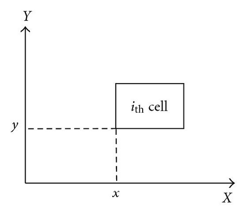
In this paper, the notation c(i, x, y) is used to denote the ith cell’s location, where x and y are presented, ith cell’s position on x-axis and y-axis, respectively. Note that, the cell positions are defined as the cell’s lower left corner. Figure 1 illustrates these definitions.
2.2. Relative and Absolute Constraints
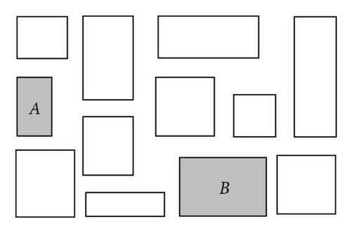
In general, placement constraints can be classified as relative and absolute. A relative placement constraint describes the relationship between two modules, and an absolute placement constraint describes the relationship between a module and the chip. Using relative placement constraints, users can restrict the horizontal or vertical distance between two modules to a certain range of values; using absolute placement constraints, the placement of a module is modified with respect to the whole chip, like restricting a cell to a certain distance from the boundary of the chip. Modules classified under either kind of constraints can be set as restriction conditions for particle movement during the PSO evolution process. Details of the definition and applications will be described in the following section.
2.3. General Use Placement Constraints
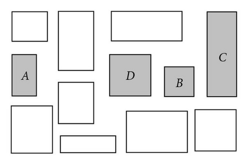
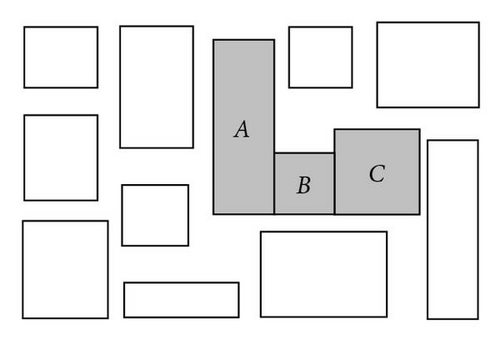
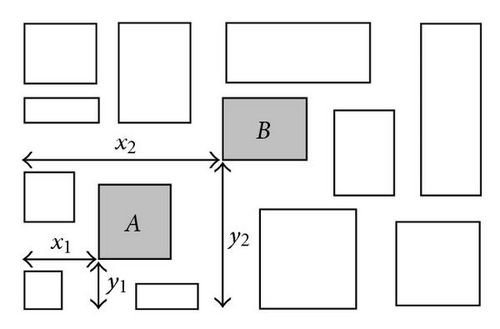
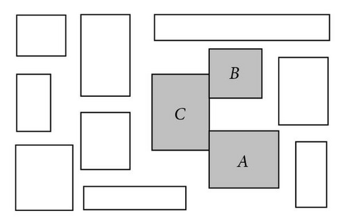
Using the above specifications for absolute and relative placement criteria, many different kinds of placement constraints can be created. In this section, a few commonly used constraints will be picked up and show how each can be specified using a combination of the relative and absolute placement constraints.
2.3.1. Alignment
2.3.2. Abutment
2.3.3. Preplace Constraint
2.3.4. Range Constraint

2.3.5. Boundary Constraint
2.3.6. Clustering Constraint
3. Particle Swarm Optimization (PSO)
The PSO is a population-based optimization technique that was proposed by Eberhart and Kennedy [17] in 1995, in which the population is referred to as a swarm. The particles exhibit the ability of fast convergence to local and/or global optimal positions over a small number of generations.
A swarm in PSO consists of a number of particles. Each particle represents a potential solution to the optimization task. All of the particles iteratively discover a probable solution. Each particle generates a position according to the new velocity and the previous positions of the cell. This is compared with the best position generated by previous particles in the cost function and the best one is kept; each particle accelerates in the direction of not only the local best solution but also the global best position. If a particle discovers a new probable solution, other particles will move closer to explore the region in more details [18].
4. PSO Algorithm for Macrocell Overlap Removal and Placement
The first step to using PSO as a way to handle the macrocell overlap removal and placement is defining each macrocell’s position as a dimension of a particle. That is, 20 dimensional particles can be used to optimize placement problems whose circuit contains 20 macrocells. The definition of the macrocells’ position is stated in the previous section. While a swarm consists of a number of particles, the particle’s movement will lead the module to find another potential or superior solution for placement. For the initial state of the placement, each module was randomly generated in the floorplanning and overlap was allowed. After a number of generations, the distance between each of the modules will shrink, meaning the chip size will get smaller. The overlap between the two modules will be eliminated by proposed overlap detection and removal mechanism.
4.1. Handling Placement Constraints by PSO
Both relative and absolute placement constraints can be set as a particle’s movement constraints and can be included in the PSO algorithm. Because of the combination of horizontal and vertical vectors into the particles’ moving vector, in this paper, a constraints handling process is instituted in the proposed floorplanner to guarantee that each macrocell’s arrangement will follow the placement constraints. Therefore, each particle can move according to the original PSO algorithm, but any moving vector that violates the setting rules (placement constraints) will be stopped by the constraints handling process; the movement of particles could be limited to one or both directions and the moving vectors could be reduced in each move to comply with the placement constraints.
Here, the two general kinds of placement constraints, absolute and relative, are taken into consideration. For relative placement constraint, users can restrict the horizontal or vertical distance between two modules to a certain value, or to a certain range of values.
In this paper, a master-slave concept is introduced to define the relationship between cells. For a set constrained macrocells, one of them will be defined as master; the others will be slaves. All the slave cells will be moved only after the master cell has moved. Furthermore, the movement strategy of slave cells will also obey the cell’s relationship defined by the constraints. For example, if cell A and cell B are both constrained to vertical alignment, and cell A is defined as the master cell, then cell B will be moved only after cell A has moved, and the x-axis of cell B will be set according to cell A’s current position. Absolute placement constraint is similarly specified except it does not involve or need the master-slave concept.
4.2. Overlap Detection and Removal Mechanism
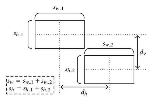
The area with an existing macrocell will be regarded as a forbidden region. If a macrocell is moved to intersect a forbidden region (overlaps with another macrocell), this macrocell will be eliminated and restored to its former location. The macrocells’ new position will be updated until it is overlap-free. This process requires more time for computation (particle movement), but it will guarantee that each macrocell’s placement is overlap-free.
4.3. Turnaround Factor for Particles’ Movement
In the original PSO, the moving vector (velocity) of each particle is decided according to its past best solution and the global best solution. This procedure makes sense in evolutional computing, where all new generations would inherit past generations’ experience or ability and move all particles toward the global best solution.
In some applications, such as placement, the optimal solution will change in each time slot. The original PSOs will ignore some of the better solutions that are beyond the particles in the searching space, and continue to drive particles toward a specific direction according to previous experiences. Particles will miss the optimal solution in the current slot and spend more time on turning particles in the right direction, and toward to the global optimal solution. Figure 9 shows the particles’ searching behavior, driven by (7) in a two-dimensional search space. It would lead particles to some searching spaces and skip the areas which have already been searched before in previous generations. This searching behavior is more suited to applications whose optimal solution is fixed at a specific position, but not time varying or dynamic. In different applications, the algorithm should be modified to be more suitable under the circumstances.
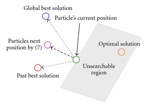
For example, in order to prevent macrocells from overlapping, all areas with existing macrocells will be regarded as a forbidden region; that is, each rearrangement of a macrocell must be overlap-free. Thus, particles may not be able to find feasible solution by moving forward (according to previous experience) in the current generation. Therefore, to search for better placement solutions, particles should not move only forwards, but also backwards to find possible solutions.
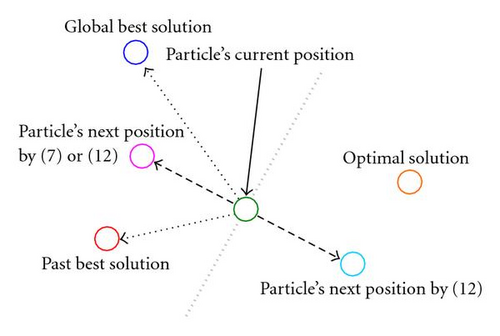
The turnaround factor can extend the particles’ searching space from the usual frontal 180 degrees to a full 360 degrees. It can stop particles from missing the solutions located behind them or located in already explored areas.
4.4. Disturbance Mechanism
In this paper, the PSO placement procedure is incorporated with a disturbance mechanism [16], the mutation-like evolutionary strategy, to prevent particles from being trapped in the local optimum.
Because each macrocell has a unique length-height ratio, after numbers of generations, the gap and free space between each macrocell should become smaller as each cell moves closer together. But it is almost unavoidable for the solution to fall into the local minimum during each particle’s search for a better placement solution.
Hence, a disturbance mechanism was added into the PSO process to prevent the search from falling into the local minimum and to escape from the trap to find the global minimal. The disturbance mechanism will pick up a particle randomly and disturb its position information; a randomly selected macrocell will be reordered in the enclosed rectangle of the floorplan while the disturbance mechanism is active. The placement process was then redone to achieve a better placement solution. Figure 11 shows that the macrocell has been replaced by disturbance mechanism.
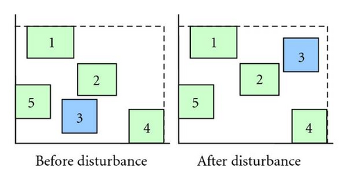
The selected macrocell will keep following the PSO iteration and continue to find new placement solutions. The disturbance mechanism will cause a slight rearrangement of the floorplan and prevent the solution from falling into the local minimum.
It takes many tries for the particles to find the best solution for the following generation. After the disturbance mechanism activates, the removed macrocell will create an empty space for other macrocells, so it can also reduce the PSO iteration time and help other macrocells find the next solution. The disturbance mechanism provides two advantages with a single process. The pseudocode of the disturbance mechanism for placement is presented Algorithm 1.
-
Algorithm 1: Pseudocode of disturbance mechanism for placement.
-
if disturbance mechanism activated
-
random select a particle (macrocell) and place it randomly
-
in the searching space (enclosing rectangle of the
-
floorplanning)
-
if overlap
-
restore the particle’s position
-
else
-
update the particle’s position
-
endif
-
endif
4.5. Objective Function
4.6. PSO for Placement Constraint and Overlap Removal
The dimension numbers N denote the number of macrocells and the particle number is defined as 1 ≤ i ≤ s. The macrocells were randomly placed on the floorplan and overlap was allowed initially. The xi represents the macrocells’ current positions and the initial state of vi,j, Pbesti, and Gbest were set to 0. After that, particles are moved by (11) and (8); vectors violating movement restraints are cut off with the constraints handling process. The overlap detection and removal mechanism will also eliminate any cells that overlap with other macrocells. Then, the new local best position would be updated with (9) and the global best position would be updated with (10). In order to guarantee that each constrained macrocell would not violate placement constraints, all constrained modules are set to have higher priority in each movement during the earlier generations to ensure that all set constraints were reached, in other words, if a nonconstrained module overlaps with a constrained module, this nonconstrained module would be removed and regenerated. Thus, all the particles would keep moving to find a better solution until it reached the goal or met the termination condition. The pseudocode of improved PSO for macrocell overlap removal and placement is presented in Algorithm 2. The dimension of each particle will be 2*N since there are 2 parameters (x- and y-axes) per cell.
-
Algorithm 2: Pseudocode.
-
Create and initiate a 2*N-dimensional PSO: P
-
Repeat:
-
Disturbance mechanism
-
Constraints handling process
-
Overlap detection and removal by (12)
-
for each particle i ∈ [1, …, s]
-
iff(xi) < f(Pbesti)
-
thenPbesti = xi
-
iff(Pbesti) < f(Gbest)
-
thenGbest = Pbesti
-
endfor
-
Until termination condition is reached
4.7. Time Complexity
In this paper, the time complexity of the proposed floorplanner is O(Nd/Np(n − 1) + d + c), where Nd is the dimensions of particles, Np the number of particles in the swarm, n is the number of macrocells, (n − 1) is overlap detection and removal (compare one macrocell with others), d is the disturbance mechanism, and c is the constraints handling process. Thus, Nd equals to n. The number of particles is typically less than n, since the number of particles in a swarm has no need to surpass a constant limit, and the activating probability of disturbance mechanism is much smaller than n2. Thus, the overall time complexity of the algorithm is O(n2).
5. Experiments
The experiments in this study employed GSRC and MCNC benchmarks [20] for the proposed placement constraints and overlap removal procedures and compared the results with other related researches. All the macrocells were set as hard IP modules and without rotation. The simulation programs were written in Matlab [21], and the results were obtained on Pentium 4 1.7 GHz with 512 MB RAM. The initial parameters of w, c1, and c2 for the proposed method and [19] were empirically set as 0.12, 0.25, and 0.25, respectively. Both their particle numbers were set as ten and the termination condition was set at 100 generations. The algorithm and parameters of ACO and B*-tree were complete following the original setting of [9] and [4], respectively. Each floorplanner was run 25 times for each of the benchmarks and their average outcomes of wire length, chip area, and run time were recorded.
The experimental results of placements are shown in Table 1. Compared with related methods, the proposed method is more efficient in finding solutions with respect to chip area or wire length and can prevent solutions fall into the local minimum. The convergence of [19] is quite acceptable. Good solutions can be found after reasonable computation time. The ACO method allows overlap in the initial stage; this means it not only has to execute the ACO procedure, detect and remove overlaps, but must also deal with constraint graphs for each macrocell. However, the ACO method shows impressive results for the floorplan. In the B*-tree structure, all macrocells are overlap-free, saving detection time to find and remove overlapping cells, but it would then spend more time arranging the cells after one cell was removed, exchanged, or placed. In a minority of cases, it displays more efficiency with placement. Once the cell number was increased, however, the computation burden of this method would increase nonlinearly, furthermore, it would likely fall into the local minimum. In unconstrained cases, the proposed method expressed more optimal results for wire length and chip area, and shorter run times than ACO [9], PSO [19], and B*-tree [4].
| Circuits | Cells | Ant Colony [9] | |||||||||||
|---|---|---|---|---|---|---|---|---|---|---|---|---|---|
| Proposed method | PSO [19] | 100 Colony 200 Ants | B*-tree [4] | ||||||||||
| Area | Wire | Run | Area | Wire | Run | Area | Wire | Run | Area | Wire | Run | ||
| (mm2) | (mm) | time | (mm2) | (mm) | time | (mm2) | (mm) | time | (mm2) | (mm) | time | ||
| ami49 | 49 | 51.46 | 179.28 | 1m52s | 58.75 | 212.75 | 1m57s | 63.32 | 218.36 | 7m58s | 50.71 | 208.38 | 1m49s |
| n_50 | 50 | 0.27 | 12.8 | 1m40s | 0.39 | 17.85 | 1m50s | 0.41 | 18.01 | 7m12s | 0.27 | 14.97 | 1m40s |
| n_100 | 100 | 0.24 | 24.17 | 3m43s | 0.41 | 35.07 | 3m51s | 0.45 | 40.36 | 15m01s | 0.27 | 31.75 | 11m39s |
| n_200 | 200 | 0.24 | 47.74 | 8m48s | 0.42 | 71.93 | 8m55s | 0.46 | 73.68 | 45m59s | 0.28 | 84.01 | 1h36m12s |
| n_300 | 300 | 0.38 | 89.84 | 15m43s | 0.40 | 132.91 | 15m59s | 0.57 | 119.43 | 1h24m1s | 0.49 | 204.44 | 5h26m50s |
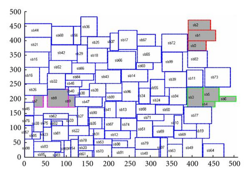
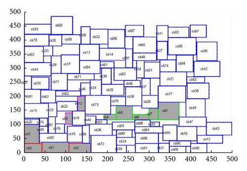
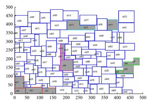
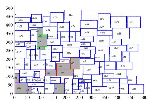
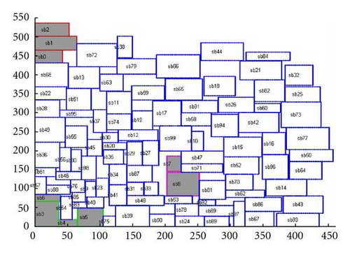
Because there are hundreds of combinations for placement constraints mentioned in Section 2, it was not possible to present every case here. In placement constraints simulation, the constraint types were selected by a random number generator. The constrained macrocells are selected by its serial number. For example, if the user wants to have 8 constrained macrocells in the GSRC n100 benchmark, cells sb0 to sb7 would be chosen. The placement constraint experimental results are shown in Table 2. Even when restricted to different numbers of macrocells during placement, the proposed method exhibited reasonable outcomes for chip size, wire length and run times, and fit all selected constraints. Furthermore, the proposed method has no cases of constraint violations in each experiment. Only little fluctuation in computation times in the proposed method when using different restricted cells can also be observed. The proposed floorplanner is more robust than related research in being more adaptable to various placement requirements. The final five multiconstraint floorplanning results in GSRC n100 were illustrated in Figures 12–16.
| Circuits | Cells | 4 macrocells in 2 random | 8 macrocells in 4 random | 12 macrocells in 4 random | ||||||
|---|---|---|---|---|---|---|---|---|---|---|
| selected constraints | selected constraints | selected constraints | ||||||||
| Area (mm2) | Wire (mm) | Run time | Area (mm2) | Wire (mm) | Run time | Area (mm2) | Wire (mm) | Run time | ||
| ami49 | 49 | 50.7 | 186.29 | 2m30s | 51.91 | 177.672 | 2m51s | 52.21 | 186.82 | 3m2s |
| n_50 | 50 | 0.28 | 13.47 | 2m26s | 0.29 | 13.65 | 3m21s | 0.3 | 13.86 | 3m56s |
| n_100 | 100 | 0.27 | 25.91 | 5m5s | 0.27 | 26.17 | 5m23s | 0.28 | 26.42 | 5m50s |
| n_200 | 200 | 0.28 | 52.11 | 10m59s | 0.28 | 52.47 | 11m18s | 0.28 | 52.95 | 12m25s |
| n_300 | 300 | 0.42 | 97.12 | 18m58s | 0.43 | 97.09 | 20m6s | 0.43 | 97.79 | 20m35s |
6. Conclusions
This paper presents a method to handle various placement constraints in floorplanning. Two techniques are introduced, which are the turnaround factor and the disturbance mechanism, to improve capability of the algorithm. When it was applied to problems without constraints, the proposed method exhibited more efficiency and robustness when searching for the solution than ACO, PSO, and B*-tree. In order to perform a wide optimal solution search, the overlap between macrocells was allowed in the initial stage, the proposed method can guarantee that all the overlaps will be eliminated in the final floorplan. The experimental results proved that the proposed method can lead to more optimal solutions within reasonable computation times for hard IP modules in unconstrained placement. Furthermore, the propose method also has ability to deal with constrained placement problems. Several benchmarks were adopted for testing and the results were very reliable. Placements with all the constraints satisfied can be obtained efficiently by the proposed method.
7. Future Works
The authors’ future works will focus on finding ways to apply their method to different architecture in order to enhance the efficiency of floorplanning, and deal with soft IP module placement problems.


