A Cadaveric Study of the Optimal Isometric Region on the Anterolateral Surface of the Knee in Anterolateral Ligament Reconstruction
Abstract
Objective
Isolated intra-articular anterior cruciate ligament (ACL) reconstruction is not capable of restoring instability in many cases leading some to recommend concomitant anterolateral ligament (ALL) reconstruction. The satisfactory fixation site and graft length change are crucial in ligament reconstruction to restore the ALL function and avoid some unwanted graft behavior. The purpose of this investigation is to determine the optimal isometric region on the anterolateral aspect of the knee for ALL reconstruction using a three-dimensional optical instrument and a suture similar to an intraoperative isometric test.
Methods
Six freshly frozen cadaveric human knees were used in this study. Data regarding the anterolateral surface were obtained using an optical measurement system to create a three-dimensional model. Nine points were selected on the femur (F1-F9) and tibia (Ta-Ti) respectively. The three-dimensional length change between each pair of tibial and femoral points was measured during passive knee flexion from 0° to 90° in 15° increments. Subsequently, five femoral points (A–E) were selected from the lateral femur, located in different areas relative to the lateral femoral epicondyle, and three tibial reference points (T1-T3) were selected in the isometric test. The changes in the length between each pair of reference points were measured using sutures. The 95% confidence interval for the rate of length change was estimated using the mean and standard deviation of the maximum rate of length change at different flexion angles, and the data were expressed as the mean (95% confidence interval) and compared with the maximum acceptable rate of change (10%).
Results
The maximum acceptable change rate for ligament reconstruction is 10%, and the mean maximum rates and the 95% confidence interval (CI) of length change for the point combinations were calculated. Among all the combined points measured using the optical measurement system and the suture, the qualified point combination for reconstruction was F3 (8mm posterior and 8mm proximal to the lateral femoral epicondyle)-Tb (8mm proximal to the midpoint between the center of Gerdy's tubercle and the fibula head), A (posterior and proximal to the lateral femoral epicondyle)-T2 (10mm below the joint line)and A-T3 (15 mm below the joint line). The position of F3-Tb and A-T2 are close to each other.
Conclusion
The most isometric area of the femur for ALL reconstruction was posterior and proximal to the lateral femoral epicondyle. We recommend that the initial location of the femoral point be set at 8 mm posterior and 8 mm proximal to the lateral femoral epicondyle and the tibial point at approximately 10 mm below the joint line, midway between Gerdy's tubercle and fibular head, and subsequently adjusted to the most satisfactory position according to the isometric test.
Introduction
Anterolateral ligament reconstruction (ALLR) is usually performed in revision anterior cruciate ligament (ACL) surgery1 and in primary cases displaying excessive anterolateral instability including young patients and other risky patients such as hyperlaxity and athletes involved in high demanding sports activities2, 3 after it is determined that an isolated intra-articular ACL reconstruction is not capable of restoring instability. However, several investigations have reported that the ALL does not show any isometry during flexion motion4, 5 and the anatomical insertion sites of the ALL are highly heterogeneous, especially at the femoral insertion site.6-12 Therefore, exact anatomical reconstruction seems not feasible in ALLR. By closely replicating the ALL anatomy and respecting the isometry of the lateral aspect, improved rotational control after surgical reconstruction may be obtained.
Different femoral and tibial points have been reported to have isometric or desirable patterns in in vitro or in vivo studies;6, 8, 11-14 additionally, several such points have been used clinically for ALLR.15 However, most of the previous studies created a bony model using radiological methods to determine the ideal point combinations on the knee, without taking the soft tissue into consideration, which cannot represent a real state of the ALL graft on the knee, and no consistent conclusion has been reached.
Each knee has its own characteristics, so the optimal isometric site should not be a fixed point for all knees but should be a relatively isometric area. In the surgical procedure, surgeons perform isometry tests to ensure that the ALL graft will not tighten in flexion and will function near extension2 using Kirschner wire (K-wire) and sutures in these areas. It is still difficult to choose the optimal graft fixation site in clinical work, and different fixation sites were reported in previous studies.15
Our study aimed to investigate the most isometric points on cadaveric knee specimens in two ways: (i) a 3D optical instrument was used to model the 3D structure of the anterolateral surface of the knee, and 3D length was measured to determine the optimal isometric regions for ALL reconstruction; and (ii) the lengths between the previously reported bone tunnel localization points or isometric points in different regions relative to the femoral epicondyle were measured to verify their isometry using sutures, similar to the isometric test in the surgical procedure.2
Materials and Methods
Specimen Preparation
Six unpaired fresh-frozen human knee cadavers from donors with a mean age of 72 years (range, 65–83 years; three male and three female donors) were obtained from a tissue bank after ethical approval was granted by the local research ethics committee (CHEC2022-029). The specimens were thawed at room temperature for 24 h before testing. The femur and tibia were cut at approximately 20 cm from the joint line. The skin and subcutaneous fat were removed, preserving the muscles and fascia. The iliotibial band (ITB) was cut at 8 cm proximal to the lateral epicondyle. The distal aspect of the ITB was then reflected distally to its attachment at the Gerdy tubercle. The deep fibers (Kaplan fibers) were resected carefully to expose the lateral aspect of the knee. The soft tissues were subsequently removed from the distal 10 cm of the tibia and proximal 10 cm of the femur for potting. The exposed femur and tibia were placed in steel pipes and rigidly fixed with polymethyl methacrylate. The femoral and tibial pipes were subsequently placed in custom-made steel tubes and secured with screws. The long axes of the pipes and tubes were carefully planned to be parallel to the femur and tibia, respectively.
Measurement Methods
First, the surface of the knee was wiped with blotting paper to absorb moisture and grease to dry it for painting. A dense surface coating was sprayed on the anterolateral surface of the knee using matte spray paint and left to dry naturally at room temperature, whereas black spray paint was uniformly sprayed onto the matte surface in granular form (Figure 1). To clarify the relative position, markers were placed at the lateral femoral epicondyle and midpoint between Gerdy's tubercle and the fibular head, which were reported to be the anatomical attachments of the ALL.16 The femoral shaft was subsequently fixed to a 6-degree-of-freedom robot (ABB IRB6700) and the tibial shaft was fixed to the experimental platform (Figure 1).
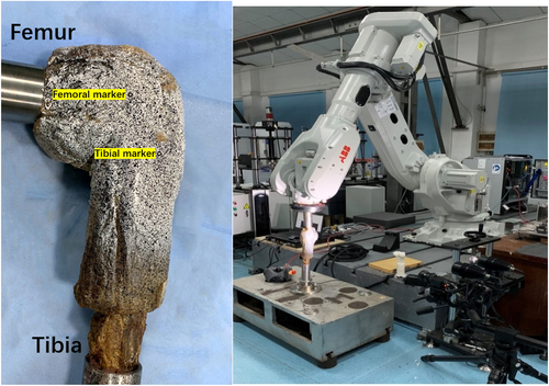
The knee was naturally flexed and extended to obtain multiple sets of femoral coordinates, which enabled the robot to simulate passive knee flexion and extension paths. The ARAMIS 3D optical measurement system (GOM mbH-Gesellschaft fur Optische Messtechnik, Braunschweig, Germany, 2448 × 2050 px, accuracy 1 × 10⁻⁵ m) was placed approximately 1.2 m away from the anterolateral aspect of the specimen and the ARAMIS 3D system was calibrated. The 3D optical instrument and robot were activated simultaneously to collect the spatial coordinate data of the target region during passive flexion of the knee specimen, resulting in a 3D image of this region (Figure 2).
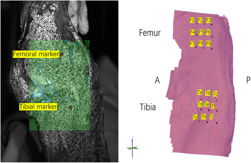
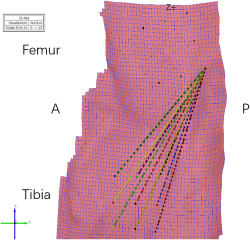
Since the width of the ALL is approximately 7.4 mm,17 the spacing between adjacent points was set to 8 ± 0.5 mm, and nine points were selected in the different regions on the anterolateral surface of the femur relative to the femoral marker, which was at the center of the lateral femoral epicondyle (point F5 in this study): F1–F9 (Figure 2). Similarly, nine tibial points were selected relative to the tibial marker (point Te, the midpoint between Gerdy's tubercle and the fibular head), Ta-Ti (Figure 2). Each femoral and tibial point can be a combination; therefore, the nine points on the femur and nine on the tibia form a total of 81 pairs. For statistical convenience and presentation, each point combination was expressed as the femoral-tibial point, as F1-Ta. The robot was used to passively flex the knee specimen to 0°, 15°, 30°, 45°, 60°, 75°, and 90°, and the three-dimensional length between each pair of combined anterolateral points was measured by the optical instrument (Figure 3).
Second, five different points of the anterolateral aspect of the femur were located using metal pins, all of which were reported in previous literature as isometric points in the anterolateral region of the knee or were used for ALL reconstruction. It was ensured that each metal pin was firmly and deeply inserted into the bone surface so that it will not loosen during knee flexion. The femoral points were selected as follows (Figure 4): point A was 7 mm posterior and 7 mm proximal to the lateral femoral epicondyle;18 point B was 5 mm posterior and 5 mm distal to the lateral femoral epicondyle;19 point C was 5 mm anterior to the lateral femoral epicondyle;16 point D was 5 mm anterior and 5 mm distal to the lateral femoral epicondyle;20 and point E was over the top position in Krackow and Brooks' study.21 Because the location of tibial points is more consistent, mostly midway between Gerdy's tubular and fibular head, approximately 10 mm below the joint line,2 three tibial points at different distances below the joint line were selected; points T1, T2, and T3 were located 5, 10 and 15 mm below the joint line, respectively as detailed in Table 1. Each point combination was expressed as a femoral-tibial point, such as A-T3. The knee was fixed on the experimental platform and flexed at 0°, 15°, 30°, 45°, 60°, 75°, and 90°. The distance between each set of points on the femur and tibia was measured three times using sutures and a slide caliper.
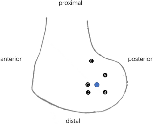
| Femoral points position (from the lateral femoral epicondyle) | |
|---|---|
| A | 7 mm posterior, 7 mm proximal |
| B | 5 mm posterior, 5 mm distal |
| C | 5 mm anterior |
| D | 5 mm anterior, 5 mm distal |
| E | over the top |
| Tibial points position (below the joint line, midway between Gerdy's tubercle and fibular head) | |
| T1 | 5 mm |
| T2 | 10 mm |
| T3 | 15 mm |
Data Analysis
The absolute lengths of the different tibiofemoral point combinations at each flexion angle were measured. The absolute length data were normalized to the rate of change. The rate of change (%) of the length22 between the point combinations at a certain flexion degree = |(absolute length at a certain flexion angle – absolute length at 0° flexion)|/ absolute length at 0° flexion × 100%. To compare the isometry of the different tibiofemoral combinations, the total change range (maximum rate of length change during 0–90° flexion) was calculated for each knee and subsequently averaged. Low values reflect near-isometry and high values denote non-isometry. A maximum length change of less than 10% meets the isometric requirement for ALL reconstruction. Previous studies have shown that ligaments that stretch by more than 10% are subjected to increased forces throughout the range of motion, which elevates the strain and deformation placed on the graft as well as the risk of failure.23, 24
Statistical Analysis
Data input was performed using Epidata and statistical analyses were performed using SAS 9.4. The 95% confidence interval for the rate of length change was estimated using the mean and standard deviation of the maximum rate of length change at different flexion angles, and the data were expressed as the mean (95% confidence interval) and compared with the maximum acceptable rate of change (10%).
Results
Three-dimensional Lengths Measured using a 3D Optical Instrument
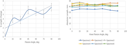
The mean values of the maximum length change rates of all point combinations measured by the optical instruments are listed in Table 2. None of the 81 combinations reflected absolute isometry. The mean values of the maximum length change rates of F2-Td, F2-Tg, and F3-Tb were less than 10% (9.6%, 9.9%, and 8.7%, respectively); however, the 95% confidence intervals of F2-Td and F2-Tg contained 10% (3.7%–15.5% and 4.7–15.0%, respectively); therefore, F3 (8 mm posterior and proximal to the lateral femoral epicondyle)-Tb (8 mm proximal to the midpoint of the line between Gerdy's tubercle and the fibular head) was the most isometric combination for ALL reconstruction. The length change rate of F3-Tb increased, whereas no significant change in its absolute length was observed with increasing flexion angle (Figure 5).
| F1 | F2 | F3 | F4 | F5 | F6 | F7 | F8 | F9 | |
|---|---|---|---|---|---|---|---|---|---|
| Ta | 24.5 (2.8–46.0) | 15.9 (7.6–24.1) | 14.8 (7.5–22.1) | 34.3 (7.5–61.1) | 22.6 (4.6–40.7) | 24.6 (10.9–38.3) | 55.4 (7.4–100.3) | 39.5 (8.3–70.7) | 18.5 (7.2–29.8) |
| Tb | 15.6 (4.2–27.0) | 14.2 (5.7–22.6) | 8.7 (7.8–9.5) | 23.2 (3.1–43.3) | 21.3 (8.1–34.6) | 14.2 (12.1–16.3) | 23.2 (5.6–40.7) | 38.2 (4.4–72.0) | 26.3 (8.5–44.0) |
| Tc | 14.8 (7.5–22.1) | 19.0 (8.8–29.3) | 15.5 (11.2–19.8) | 19.9 (11.1–28.8) | 25.1 (13.7–36.5) | 27.7 (15.2–40.2) | 29.5 (3.8–55.2) | 34.6 (7.8–61.4) | 36.7 (5.9–67.5) |
| Td | 22.3 (5.1–39.5) | 9.6 (3.7–15.5) | 18.1 (12.1–24.1) | 27.2 (4.9–49.4) | 18.8 (4.8–32.9) | 22.8 (9.0–366) | 45.3 (3.0–87.6) | 29.8 (8.1–81.5) | 18.7 (8.8–28.5) |
| Te | 18.6 (5.5–31.7) | 13.7 (5.9–21.5) | 16 (10.4–21.6) | 21.9 (0.8–42.9) | 17.5 (7.5–27.5) | 21.3 (10.8–31.7) | 35.6 (0. 0–71.3) | 25.1 (0.0–50.4) | 19.6 (5.3–33.9) |
| Tf | 15.5 (10.8–20.1) | 20.0 (13.1–27) | 13.8 (9.2–18.4) | 26.4 (11.9–41.0) | 19.2 (11.7–26.7) | 25 (15.6–34.4) | 29.3 (0.0–60.3) | 18.4 (7.5–29.3) | 30.9 (4.2–57.9) |
| Tg | 20.8 (5.1–36.5) | 9.9 (4.7–15.0) | 16.9 (11.9–22.0) | 20.6 (5.6–35.7) | 15.8 (5.1–26.4) | 18.3 (7.3–29.4) | 34.9 (8.6–61.2) | 20.6 (2.3–39.0) | 17.2 (11.7–22.6) |
| Th | 15.3 (7.1–23.4) | 13.6 (8.9–18.2) | 17.4 (12.5–22.3) | 17.6 (1.3–33.8) | 15.7 (5.2–26.3) | 20.2 (13.1–27.2) | 29.8 (1.4–58.2) | 21 (0.0–42.3) | 15.7 (5.1–26.3) |
| Ti | 14.0 (8.4–19.5) | 19.0 (12.5–25.4) | 18.2 (9.1–27.4) | 16.4 (7.5–25.3) | 16.6 (9.7–23.4) | 24.2 (17.3–31.1) | 25.1 (2.4–47.8) | 20.4 (4.9–35.9) | 22.0 (5.0–39.0) |
- Note: Data are reported as mean values (95% CI); mean values less than 10% are in bold type.
Length Change Rates Measured Using Sutures
The mean values and 95% confidence intervals of the normalized maximum length change rates for each point combination during passive knee flexion of 0–90° are detailed in Table 3, which shows that no combination is truly isometric. Fixation at point A (7 mm posterior and 7 mm proximal to the lateral epicondyle of the femur25) and point E (over the top21) demonstrated length change rates of less than 10% for all point combinations (8.1%, 7.6%, 7.7%, 7.2%, 5.1%, and 6.6%, respectively). Among the above six combinations, the 95% confidence interval of the mean maximum length change rate of five combinations, including A-T2, A-T3, E-T1, E-T2, and E-T3, did not contain 10% and met the requirement for isometric ALL reconstruction, while the 95% confidence interval of the mean length change value of the A-T1 combination (4.2%–11.9%) contained 10% and did not meet the standard.
| A | B | C | D | E | |
|---|---|---|---|---|---|
| T1 | 8.1 (4.2–11.9) | 10.4 (6.7–14.1) | 10.3 (7.0–13.6) | 13.5 (10.7–16.3) | 7.2 (6.1–8.3) |
| T2 | 7.6 (6.3–8.9) | 11.7 (8.7–14.8) | 11.6 (10.0–13.2) | 11.8 (10.1–13.5) | 5.1 (3.2–7.0) |
| T3 | 7.7 (5.5–9.9) | 11.0 (8.6–13.4) | 13.5 (10.8–16.3) | 15.2 (12.6–17.9) | 6.6 (3.6–9.5) |
- Note: The data are reported as mean values (95% CI); mean values less than 10% are in bold type.
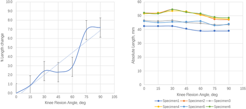
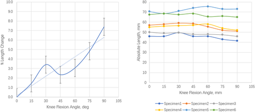
Point E (over the top) was used in a sling and reef procedure in 1978,26 as a combined “over the top” procedure for both ACL reconstruction and extra-articular plasty, the extra-articular graft fixation point is far from the femoral attachment of ALL, which is completely different from the ALL anatomy reported. Although they reported good clinical results, it seems not appropriate for an anatomic ALL reconstruction which is usually not combined with “over the top” ACL reconstruction; therefore, in this study only combinations of A-T2 and A-T3 were chosen for further analysis. A further analysis of the rate of change in length of these two combinations demonstrated a tendency to increase as the knee flexion angle increased. There was no significant fluctuation in the absolute lengths between the combined points; however, there was a tendency for a slight decrease as the knee flexion angle increased (Figure 6 and 7).
Discussion
The most important finding of the present study was that we determined the most isometric area on the femur for ALL reconstruction is posterior and proximal to the lateral femoral epicondyle on the 3D surface model of the knee, which can represent the true state of the graft on the surface of the knee. To the best of our knowledge, this is the first study to evaluate the three-dimensional length change of point combinations on the real knee surface model using the optical measurement system.
Impossibility of Exact Anatomic ALLR and Disadvantage of Previous Techniques for Isometric Studies
Ligament reconstruction is based on anatomical and isometric studies; additionally, isometry is more crucial when using a synthetic graft because synthetic ligaments are less stretchy than autologous grafts, and identification of locations that optimize length and change patterns is important. Historically, the first observations of the ALL can be traced back to the French anatomist Paul Segond who reported a “pearly fibrous resistant band” showing extreme amounts of tension under excessive internal rotation resulting in an avulsion fracture as a result of severe rotational stress in 1879.27 In 1976 Hughston et al. described the “middle third of the lateral capsular ligament” as “technically strong,”28, 29 and in 1982, Müller30 reported on the anatomy of the “anterolateral femorotibial ligament” as a distal, posterior portion of the iliotibial tract extending from the linea aspera of the femur to Gerdy's tubercle. Then, ALL was recovered and first described as an independent ligamentous structure with accurate anatomical description by Claes et al.6 in 2013. Since then, several studies have been conducted to further clarify the femoral and tibial attachments; however, controversy is still observed. First, ALL is not found in all human specimens, and the identification rate of ALL varies from 12% to 100%.14, 17, 31-33 Second, the femoral and tibial attachments of ALL are highly variable according to previous studies, especially the femoral attachment. Daggett et al.7, 8 found that the femoral attachment was located posterior and proximal to the lateral epicondyle or directly on the lateral femoral epicondyle, whereas Claes et al.6 found that the femoral attachment of the ALL was located slightly anterior to the lateral collateral ligament attachment. The tibial attachment is less controversial and is mostly located midway between Gerdy's tubercle and fibular head. In addition, numerous previous studies have demonstrated that the ALL is not an isometric structure, so it is not feasible to perform a complete anatomical reconstruction of the ALL.
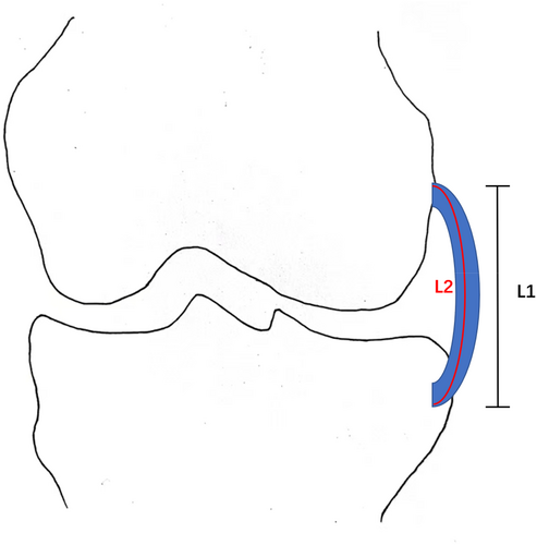
Isometric studies of the anterolateral region of the knee were reported as early as the era when lateral extra-articular tenodesis (LET) was popular.21, 34 With the introduction of ALL and advancements in technology, studies on isometry for ALL reconstruction began to emerge by various means. Similar to the results of studies on the anatomy, the position of the isometric point on the tibia was relatively consistent, mostly located midway between Gerdy's tubercle and fibular head, whereas the isometric point on the femur was more controversial. Several studies have measured the length using radiological methods like MRI, 3D CT, or dual fluoroscopy,13, 16, 35 which can only measure the linear length between combined points on the surface of soft tissue or create a bony, three-dimensional model of the knee to measure the length between the femorotibial points without taking the soft tissues into account. Therefore, it is difficult to represent the true length of the ALL graft on the surface of the knee using radiological methods (Figure 8).
Advantage of the 3D Optical Measurement System and the Most Desirable Graft Fixation Site
In this study, considering that the real knee surface is not flat and there is soft tissue on it, the anterolateral surface of each specimen was scanned in this experiment using the 3D optical measurement system. A three-dimensional model of the scanned area was established to measure the three-dimensional length between the point combinations at different knee flexion angles, and subsequently the rate of length change was calculated. The lateral femoral epicondyle and midpoint between Gerdy's tubercle and fibular head were the reference points on the femur and tibia, respectively; it was found that only the mean value of the maximum change rate of F3-Tb was less than 10%,16 which was within the acceptable range for reconstruction. Point F3 is located in the proximal and posterior regions of the lateral femoral epicondyle, and point Tb is located slightly proximal to the midpoint between Gerdy's tubercle and the fibular head, which is consistent with the isometric studies conducted by Imbert et al.25 and Kernkamp et al.,13 as well as with the recommendation for ALL reconstruction of the 2017 ALL Expert Consensus.2 Several reported anatomical attachments are also within the scanned region (e.g., F5-Te,16 which had a length change rate of 17.5%); additionally, none of these sites showed good isometry, demonstrating that ALL does not show any isometry anatomically.
Previous studies of isometry in the anterolateral region of the knee, both in vitro and in vivo, have obtained different results,25, 34, 36, 37 especially for the isometric points on the femur, located in different regions relative to the lateral femoral epicondyle. The isometric test is commonly utilized using sutures and K-wires in surgical procedures.2 Therefore, a similar approach to the intraoperative isometric test was used to quantify the isometry and determine the most isometric region for ALL construction, in which the length between the femorotibial points was measured using sutures during knee motion. The femoral points (located in different regions relative to the lateral femoral epicondyle) and tibial points reported in previous studies were selected to represent different areas on the anterolateral surface in this investigation. Compared to the maximum acceptable length change rate of 10% for ALL reconstruction,18 it was found that two combinations corresponding to point A (7 mm posterior and 7 mm proximal to the lateral femoral epicondyle) had relatively good isometry, which is in line with Imbert et al.25 and Kernkamp et al..13 As reported in many studies on the quantitative anatomy of ALL, Gerdy's tubercle was approximately 17.1mm below the joint line, so the point Tb (8mm proximal to the midpoint between Gerdy's tubercle and the fibular head) in this optical study is closer to the point T2 (10 mm below the joint line midway between Gerdy's tubercle and the fibular head) in the manual isometric test. Therefore, the results of these two measurement methods in this study are consistent, indicating good isometry of the point combinations between the posterior and proximal regions relative to the lateral femoral epicondyle and the point at 10 mm below the joint line midway between Gerdy's tubercle and the fibular head. It was also found that over the top position in Krackow and Brooks' study,21 which was point E in this experiment, located more proximal to the lateral femoral epicondyle, showed better isometry in combination with all three tibial points. However, as mentioned above, the graft fixation in the extra-articular plasty in “over the top” procedure is far from ALL anatomy reported, and it seems inappropriate for an anatomic ALL reconstruction which is commonly combined with intra-articular ACL reconstruction instead of “over the top” ACL reconstruction. Point D (5 mm anterior and 5 mm distal to the lateral femoral epicondyle), referring to the femoral point selected by Wagih and Elguindy20 when using a synthetic graft for ALL reconstruction, was selected in this study, which was thought to have satisfactory isometry; however, the results revealed that during knee flexion, point D demonstrated significant non-isometry, which cannot be a reference point for ALL reconstruction, especially for the use of a synthetic graft.
Prospect of Clinical Application and Limitations
In summary, the most isometric region on the femur is located posterior and proximal to the lateral femoral epicondyle and on the tibia at the point approximately 10mm below the joint line, midway between Gerdy's tubercle and the fibular head. There was a tendency for the length change rate between the most isometric femorotibial points to increase and for the absolute length to decrease with an increasing flexion angle, although the change was smaller. This also means that after the fixation of the ALL graft in the isometric region at 0° of flexion, the graft can maintain isometry throughout the range of motion without excessive tension and will gradually become slightly relaxed at the high flexion angle, which meets the requirement for ALL reconstruction provided by the 2017 ALL Expert Consensus2 and also consistent with the normal property of ALL.38
We believe our results can be used to optimize ALL reconstruction techniques. In clinical work, the results of this isometric study can be used as an effective guide for the selection of bone tunnel localization points; however, it is still necessary to select the most appropriate localization point for a specific individual after intraoperative isometric testing in a relatively isometric area. Further study should focus on the biomechanical performance of our results and investigate whether the more isometric ALL reconstruction would better restore internal instability of the knee than those relatively non-isometric reconstructions.
This study had several limitations. First, only a small number of elderly knee specimens were investigated, which were considerably older than the typical patient suffering from ACL injuries, which is often the case in cadaveric studies. Second, the absolute lengths between the femorotibial points were normalized by comparison with the absolute lengths at 0° flexion, which was based on previous studies39, 40 and the recommendation by the 2017 ALL Expert Consensus2 that the ALL graft should be fixed when the knee is fully extended. The “normalization” can help to avoid the bias created by different knee sizes. However, the results can be best applied to ALL reconstruction, in which the graft is fixed at 0° flexion. Lastly, this cadaveric study focused on the graft isometry in the ALL reconstruction which is usually used to control the internal tibial rotation, so the true effect of our results should be evaluated in further biomechanical and clinical research.
Conclusion
The most isometric area on the femur for ALL reconstruction is posterior and proximal to the lateral femoral epicondyle. We recommend that the initial location of the femoral point be set at 8 mm posterior and 8 mm proximal to the lateral femoral epicondyle and the tibial point at approximately 10 mm below the joint line, midway between Gerdy's tubercle and fibular head, and then adjusted to the most satisfactory position according to the isometric test.
Author Contributions
Gai Yao and Yang Liu contributed equally to this article. Gai Yao, Yang Liu, Zhiyou Zhou, Zimin Wang and Zikai Hua contributed to study design. Gai Yao, Yang Liu, and Xuchao Zhang conducted the experiment. Gai Yao, Yang Liu, Kang Liu, and Xiawei Fu were responsible for the data collection and supervised the study. Zhiyou Zhou and Kang Liu performed statistical analysis. Gai Yao and Yang Liu wrote the manuscript. Zimin Wang and Zikai Hua aided in analyzing the data and drafting the manuscript. Zi-min Wang and Zikai Hua were responsible for supervision, writing – review & editing, and project administration. All authors have read and approved the manuscript.
Acknowledgments
This study was supported by National Natural Science Foundation of China (81572211, 81972060). We also appreciate the assistance received from Orthotek Laboratory, School of Mechatronics Engineering and Automation, Shanghai University for consultation.
Ethics Statement
This investigation obtained approval from Shanghai Changhai Hospital Ethics Committee(CHEC2022-029).
Conflict of Interest Statement
The authors declare no conflict of interest.


