High-pressure polymorphs of magnesian orthopyroxene from a shock vein in the Yamato-000047 lherzolitic shergottite
Abstract
Abstract– We found a simple thin shock vein, less than or equal to about 60 μm in width and 1.8 mm in length, in the poikilitic area in the Yamato (Y-) 000047 lherzolitic shergottite. The shock vein occurs only in magnesian Ca-poor clinopyroxene, which may have transformed from orthopyroxene during the pressure increase at the shock event. The shock vein consists of (Mg0.8,Fe0.2)SiO3 pyroxene polymorphs, such as columnar akimotoite, two kinds of pyroxene glasses, dendritic akimotoite, and framboidal pyroxene glass, in the order from the periphery to the center. The compositions and textures suggest that columnar akimotoite in the periphery of the shock vein crystallized from solid-state phase transition of clinopyoroxene during the cooling of the vein, and the remains in the shock vein solidified from shock-produced melt. The glass includes two kinds of massive glass in the vein and framboidal glass in the vein center. The framboidal glass is the most magnesian and may have been vitrified from perovskite crystallized from high-pressure melt produced at high temperature ≥3000 °C and high-pressure 23–40 GPa. Dendritic akimotoites in the vein center metastably crystallized from residual shock melt. The formation sequences of the constituent phases in the shock vein happen in the following order: columnar akimotoites, rim glass, center glass, framboidal glass, and dendritic akimotoites. The increase of the Raman intensity of 660–670 cm−1 in the order of rim glass, center glass, and framboidal glass suggests that the formation of the pyroxene chain proceeds faster in the vein center than in the vein rim due to its slower cooling. The finding of the shock vein consisting merely of high-pressure polymorphs of pyroxene, akimotoite, and framboidal glass (vitrified perovskite) is the first reported among all Martian meteorites.
Introduction
High-Pressure Phases in Martian Meteorites
Eighty-nine Martian meteorites of 74 shergottites, 8 nakhlites, 2 chassignites, 1 orthopyroxenite, and 4 unclassified have been known so far, and they have been mostly recovered from Antarctica and hot deserts in north Africa (Meteoritical Bulletin Database, http://tin.er.usgs.gov/meteor/metbull.ph). All Martian meteorites show characteristic textures derived from the intense impact shock on the Martian surface. The strong shock textures in shergottites are characterized of normal plagioclase glass or maskelynites transformed from plagioclase, and deformation features in olivines and pyroxenes (e.g., Ikeda 1994; McSween 1994). Shock melt pockets including glass have been observed in most shergottites (Ikeda 1994; Wang and Chen 2006; Walton and Herd 2007). Despite possible impact shocks on the Martian surface, the reports of high-pressure phases in Martian meteorites have been restricted to a small number of Martian meteorites: hexaluminosilicate and stishovite from shock melt pockets (Beck et al. 2004), post-stishovite (Sharp et al. 1999; El Goresy et al. 2000), stishovite, hollandites, akimotoite, and amorphosed perovskite (Langenhorst and Poirier 2000), and pyroxene glass (Bell et al. 1999) from shock melt veins.
Paired lherzolitic shergottites, Yamato (Y-) 000027, Y-000047, and Y-000097 (hereafter Yamato 00 lherzolitic shergottites), have been recovered from the bare ice field near the Yamato Mountains in Antarctica (Imae et al. 2002), and these three meteorites have been classified into lherzolitic shergottites (Kojima 2006; Misawa et al. 2006). These are paired based on the near sampling location and the similar mineralogical and petrological features (e.g., Mikouchi and Kurihara 2008).
We have first reported high-pressure polymorphs of three kinds of pyroxene glass and two kinds of akimotoites in shock veins only occurring in poikilitic area in Y-000047 in the 31st Symposium on Antarctic Meteorites (Imae and Ikeda 2007). In this study, we describe them in more detail and discuss their formation history.
MgSiO3 Polymorphs
Five high-pressure polymorphs have been experimentally synthesized for MgSiO3: high-pressure clinoenstatite (the space group of C2/c, Shinmei et al. 1999), majorite (the space group of I41/a, Angel et al. 1989), akimotoite (the space group of R ), perovskite phase (the space group of Pbnm, e.g., Wang et al. 1992), and post-perovskite phase (the space group of Cmcm, Murakami et al. 2004). The equilibrium stability field of MgSiO3 polymorphs has been thermodynamically obtained on the P–T phase diagram (Gasparik 1990a,b).
Majorite was first synthesized by Ringwood (1967), and discovered from the Coorara L6 chondrite (Smith and Mason 1970). Thereafter, majorites have been reported from the Suizhou L6 chondrite (Chen et al. 2004), the Tenham L6 chondrite (Xie and Sharp 2007; Xie et al. 2006a, 2006b) and from the Y-75267 H6 chondrite (Kimura et al. 2003). Akimotoite is MgSiO3 with ilmenite structure, which was first synthesized by Kawai et al. (1974). The crystal structure was determined by Liu (1976). Much later, akimotoite has been identified from the nature in shock veins in the Tenham L6 ordinary chondrite (Tomioka and Fujino 1997), the Acfer 040 L6 chondrite (Sharp et al. 1997), the Y-75267 H6 chondrite (Kimura et al. 2003), the Umbarger L6 chondrite (Xie and Sharp 2004), the Y-791384 L6 chondrite (Ohtani et al. 2004), and the Sixiangkou L6 chondrite (Zhang et al. 2006). Perovskite phase was first synthesized by Liu (1974). The perovskite phase (Tomioka and Fujino 1997) was identified from the same meteorite, Tenham, with finding of akimotoite, and the vitrified perovskite phase was also identified from the same meteorite, Acfer 040, with the finding of akimotoite (Sharp et al. 1997), indicating that these perovskite phases coexisted with akimotoites. High-pressure clinoenstatite (C2/c) transforms into clinoenstatite (P21/c) at room condition (Demelza et al. 1994; Shinmei et al. 1999), and it is unquenchable phase. Remnant of high-pressure clinoenstatite has been identified.
As the Mg/Si atomic ratio of the cosmic abundance is nearly unity (Anders and Grevesse 1989), the five high-pressure polymorphs of MgSiO3 (Gasparik 1990a, 1990b; Murakami et al. 2004) are possible main phases of rocky planet interiors and the stable phase among them depends on the size of planets and their depths. It is very important to study the MgSiO3 polymorphs in the shock vein of meteorites, as the present shock vein including only high-pressure polymorphs of MgSiO3 occurs only in the oikocrystic low-Ca clinopyroxene transformed from orthopyroxene in the poikilitic area.
Analytical Methods
A polished thin section of Y-000047,41-1 was used for this study, and its surface area is 23 mm2. Polished thin sections of Y-000027 (41-1, 22 mm2) and Y-000097 (51-1, 85 mm2) were also used for reference. An electron-probe microanalyzer (EPMA; JEOL JXA-8200) at the National Institute of Polar Research was used for the chemical analyses of minerals and glass. The beam current was 11 nA with a focused beam. The counting time of the Kα peak position of each element for standards and unknown phases was 10 s, and the counting time of the background for them was 5 s. The Bence and Albee corrections were applied for silicates. The standards for the analytical elements (Taylor Corporation Multi-element Standard, No. 202-52 and Astimex No. 01-045) are as follows: natural magnesian olivine for MgO, natural wollastonite for CaO and SiO2, synthetic hematite for FeO, synthetic Cr2O3 for Cr2O3, natural orthoclase for K2O, natural albite for Na2O, natural spessartine for MnO, synthetic corundum for Al2O3, synthetic rutile for TiO2, natural apatite for P2O5, synthetic NiO for NiO, and synthetic V2O5 for V2O3. The following crystals for spectroscopy were used: (1) TAP for Si, Mg, Na, and Al; (2) PET for K, Ca, Ti, P, Cr, and V; and (3) LiF for Fe, Mn, and Ni. The overlapping correction of VKβ (=73.011 mm) on CrKα (=73.256 mm) for the PET crystal was carried out with the correction factor of 0.11530.
The Raman spectra were obtained for pyroxenes and the high-pressure polymorphs on the polished thin section using a JASCO NRS-1000 Raman microspectrometer at the National Institute of Polar Research. Measurement conditions were as follows: a focused green laser beam with a wavelength of 531.91 nm with an intensity of 11 mW, analyzing area of about 1 μm in diameter, the measuring sequence 10 s × 3. The calibration of the wavelength for Raman shifts was carried out using the strongest peak of Si (520.5 cm−1). We checked the intact state of analyzed points after the measurement by observing the analyzed points using a reflective optical microscope installed with the spectrometer and by comparing Raman spectra obtained by multiple analyses.
Summary of Petrology for the Paired Yamato 00 Lherzolitic Shergottites
Petrography of Two Main Lithologies and Shock Veins
The Yamato 00 lherzolitic shergottites consist of two main areas, poikilitic and non-poikilitic (e.g., Mikouchi and Kurihara 2008), previously known as lherzolitic shergottites (e.g., Ikeda 1994, 1997, 1998), although the polished thin section of Y-000047 consists only of the poikilitc area. Detailed petrographic descriptions for the Yamato 00 lherzolitic shergottites have been described (e.g., Mikouchi and Kurihara 2008). Here, we briefly summarize the textures and compositions, and propose the summary of the crystallization history from the parent magma.
Large oikocrystic low-Ca pyroxenes (Ca-poor clinopyroxene and pigeonite) of up to about 8 mm occupy most of the poikilitic area (Figs. 1a and 1b). The Ca-poor clinopyroxene transformed from orthopyroxene during the shock metamorphism. Oikocrystic low-Ca pyroxenes are magnesian with the compositional range of En66–77Fs21–23Wo2–11, and include chadacrystic rounded olivines (Fa26.5–32). Minor augites (Fe# = 21–24, En47–53Fs13–14Wo33–40) also occur in the poikilitic area (Fig. 1c). Chromites in the poikilitic area are mainly enclosed in pyroxenes; the composition of chromites is Cr-richer and lower in Fe# than that of the non-poikilitic area. In the non-poikilitic area, low-Ca pyroxenes are much smaller (<1 mm) than those in the poikilitic area, and have the composition of En58–69Fs23–25Wo8–17 (Fe# = 28–33). They coexist with augites (Fe# = 20–25, En45–55Fs13–18Wo27–42), coarser grained olivines (Fa30–35), and maskelynites (An43–49Ab40–54Or1–3) in the non-poikilitic area. Some maskelynites (An34–62Ab37–62Or1–4) in Y-000097 show hourglass structure, consisting of An-rich wide sector (An52–56) and Ab-rich narrow sector (An48–55), suggesting that the interstitial melt for the lherzolitic shergottite have supercooled to crystallize primary igneous plagioclase (Imae and Ikeda 2007). Chromites in the non-poikilitic area consist of Cr-rich core and Ti-rich rim both with lower Mg# (=11–20) than those (19–28) in the poikilitic area. Minor minerals are ilmenite, pyrrhotite, pentlandite, merrillite, Cl-apatite, and baddeleyite in the non-poikilitic area. Trapped melt compositions estimated from magmatic inclusions have been shown by Ikeda and Imae (2007).
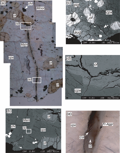
a) The striking shock vein (indicated as Major) in Y-000047 only occurs in the poikilitic area (transmission light). The pyroxene phase in the area solely consists of Ca-poor clinopyroxene transformed from orthopyroxene during the shock event, but not pigeonite and augite. Weak shock vein (indicated as Minor) appears on the other side of the olivine grains. The white rectangles indicate the areas of (d) and (e). The side is 1.25 mm. b) Backscattered electron (BSE) image of the lower half of (a), showing the shock vein. c) Pigeonite and augite in the poikilitic area in Y-000047 under a high-contrast BSE image in order to be distinguished pyroxenes. The area of (c) is outside of the area (a). d) A fault in a chadacrystic olivine grain due to the shock vein formation (BSE image). e) The shock vein under the optical microscope (transmission light). Width of the figure is 125 μm. ol, olivine; cpx, Ca-poor clinopyroxene; chr, chromite; pig, pigeonite; aug, augite; Fr-Aggr, framboidal aggregates; Col, columnar crystal; Gl, glass.
The three lherzolitic shergottites commonly include shock veins, although the textures of shock veins are different among the three specimens (Mikouchi and Kurihara 2008). The vein in Y-000027 is much thicker than the other two shergottites, and is 1.8–2.2 mm in width and 5.3–5.4 mm in length. It mainly consists of euhedral magnesian olivine (Fa∼18 and ≤ ∼7 μm in size), coarse-grained anhedral relict olivines (several hundreds μm), a coarse-grained anhedral relict low-Ca pyroxene (several hundreds μm, En74.1Fs21.5Wo4.4), and interstitial glass. Euhedral olivines seem to have crystallized from shock-produced melt, suggesting that they crystallized at low pressure after the release of high-pressure. Thin shock veins, less than about 100 μm, and several small shock melt pockets in Y-000097 occur in the poikilitic area, and the interiors of the shock veins include tiny bubbles, suggesting that the pressure was released probably during the crystallization. Thin shock veins in Y-000047, less than about 60 μm in width, also occur only in the poikilitic area. The shock melting occurs only in the oikocrystic low-Ca pyroxene, and there are no bubbles like those in Y-000097.
Summary of Crystallization History from the Parent Magma
The crystallization sequence of minerals for the Yamato 00 lherzolitic shergottite is summarized below (e.g., Ikeda and Imae 2007; Imae and Ikeda 2007; Mikouchi and Kurihara 2008). As chromite and olivine are mainly trapped in magnesian low-Ca pyroxenes (orthopyroxene and pigeonite) in the poikilitic area, they may be liquidus phases. The poikilitic lithology suggests that magnesian olivine (Fa26–30), pyroxenes of orthopyroxene (Fe# = 21–23.5) and magnesian pigeonite (Fe# = 23–28), and Cr-rich chromite (Mg# = 25–28) are cumulus phases, which crystallized from a parent magma and accumulated on the floor of a magma chamber or a sill. However, ferroan olivine (Fa30–35), ferroan pigeonite (Fe# = 28–33.5), augite (Fe# = 20–25), plagioclase, phosphates, and sulfides crystallized from fractionated melts mostly to form the non-poikilitic lithology. Cumulus minerals of olivine, pigeonite, and chromite in contact with intercumulus melt overgrew to form rims with mineral compositions in the non-poikilitic lithology. During the overgrowth, the diffusion of Cr–Ti between cumulus and overgrown chromites and that of Fe–Mg between cumulus and overgrown pigeonites did not occur due to their slow diffusion rates. However, the diffusion of Fe–Mg in olivine and that in chromite between cumulus and overgrown phases may have taken with place with each other in some degree. On the other hand, plagioclase nucleated directly from the intercumulus melt, suggesting that a large degree of supercooling is necessary for the crystallization of plagioclase. The rapid crystallization condition of plagioclase in the non-poikilitic lithology may have formed the hourglass structure.
Results
Textures and Electron-Probe Microanalyses of the Shock Vein
1-3 show the overall features of the shock vein. A shock vein of the Y-000047 lherzolitic shergottite is denoted by Main in Figs. 1a and 1b. The vein seems to contact with another vein (Minor in Fig. 1a) at a chadacrystic olivine grain in the upper part of the figure. The shock vein occurs only in Ca-poor clinopyroxene transformed from orthopyroxene (Figs. 1a and 1b), but never in pigeonite and augite (Fig. 1c). The chadacrystic olivine grain makes a dislocation of about 20 μm (Fig. 1d), suggesting that the relative movement for the slip to form the shock vein seems to be small.
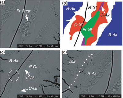
a) A high magnification image of the shock vein under the backscattered electron image. b) The schematic illustration showing the phase distribution in the shock vein in the area of (a). c) A high magnification image of the shock vein showing a bridge in a crack under the back-scattered electron image. d) A high magnification image of the shock vein rim of columnar akimotoites. cpx, Ca-poor clinopyroxene; Fr-Aggr, framboidal aggregates; R-Ak, rim akimototite; R-Gl, rim glass; C-Gl, center glass; C-Ak, dendritic akimotoite in the vein center; Fr-Gl, framboidal glass.
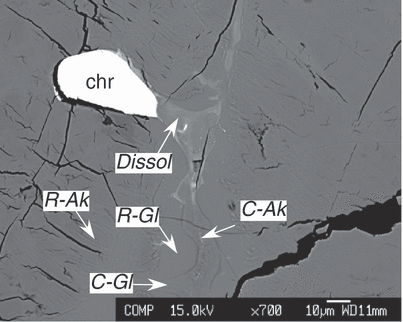
The shock vein partially dissolving chromite indicated as Dissol. chr, chromite; R-Ak, rim akimototite; R-Gl, rim glass; C-Gl, center glass; C-Ak, dendritic akimotoite in the vein center.
Figure 2 shows the detailed textures observed in the shock vein. Figure 2a shows a close-up image of the shock vein, consisting mainly of glasses and high-pressure phases. Figure 2b shows the schematic illustration of Fig. 2a. A crack along the shock vein is distinct (1, 2). As the pyroxene glass crosses the crack indicated within a circle in Fig. 2c, the crack would have formed at the time of shock melt vein formation.
The vein rim shows angular or columnar texture coexisting with pyroxene glass (R-Ak in Fig. 2d). The mode of the columnar texture in the vein rim is the most abundant in the shock vein, occupying about 48 modal%. The vein rim continuously changes to Ca-poor clinopyroxene toward the host clinopyroxene (Fig. 2d). The columnar phase in the vein rim (Col in Fig. 1d and R-Ak in Fig. 2d) have Fe# = 21–23. The intermediate between the rim and center of the vein is glassy, and it is R-Gl (rim glass) and C-Gl (center glass) in Fig. 2b. The mode of rim glass occupies about 38 modal%, and that of center glass <14 modal%. Compositions of columnar phase (R-Ak in Fig. 2d) and glassy phases (C-Gl and R-Gl in Figs. 2a and 2b) are similar to each other (Table 1, Fig. 4), and their compositions of En76.6–74.6Fs20.3–22.3Wo3.1–3.2 are identical with those of the Ca-poor clinopyroxene in the poikilitic area (Table 1, Fig. 4).
| Akimotoite in the vein rim (n = 15) | Glass in the vein rim (n = 14) | Glass in the vein center (n = 7) | Akimotoite in the vein center (n = 3) | Framboidal glass (n = 12) | Pyroxene glass effected by chromite | Ca-poor clinopyroxene | Analytical error (1σ) | Pigeonite | Augite | |
|---|---|---|---|---|---|---|---|---|---|---|
| SiO2 | 55.36 | 55.01 | 55.11 | 54.46 | 55.59 | 52.35 | 54.77 | 0.3 | 54.17 | 52.72 |
| TiO2 | 0.07 | 0.08 | 0.06 | 0.09 | 0.08 | 0.15 | 0.14 | 0.03 | 0.10 | 0.22 |
| Al2O3 | 0.30 | 0.36 | 0.39 | 0.33 | 0.36 | 0.68 | 0.33 | 0.03 | 0.42 | 1.11 |
| Cr2O3 | 0.42 | 0.46 | 0.46 | 0.50 | 0.39 | 2.62 | 0.42 | 0.05 | 0.46 | 0.9 |
| NiO | 0.05 | n.d. | 0.01 | 0.00 | 0.03 | 0.09 | n.d. | 0.03 | n.d. | n.d. |
| FeO | 14.08 | 13.93 | 14.12 | 15.50 | 12.85 | 14.75 | 14.12 | 0.3 | 14.83 | 9.49 |
| MnO | 0.39 | 0.52 | 0.43 | 0.47 | 0.49 | 0.44 | 0.46 | 0.06 | 0.39 | 0.43 |
| MgO | 27.71 | 27.60 | 27.68 | 26.67 | 28.87 | 25.34 | 28.07 | 0.2 | 25.63 | 18.31 |
| CaO | 1.60 | 1.58 | 1.58 | 1.59 | 1.64 | 1.81 | 1.54 | 0.03 | 2.53 | 15.53 |
| Na2O | 0.03 | 0.03 | 0.04 | 0.02 | 0.03 | 0.05 | 0.03 | 0.02 | 0.08 | 0.15 |
| K2O | 0.01 | 0.01 | 0.01 | 0.01 | 0.01 | 0.03 | 0.01 | 0.01 | 0.00 | 0.01 |
| P2O5 | 0.03 | 0.02 | 0.05 | 0.01 | 0.02 | 0.00 | n.d. | n.d. | n.d. | n.d. |
| V2O3 | 0.03 | n.d. | 0.03 | 0.03 | 0.03 | 0.10 | n.d. | 0.02 | n.d. | n.d. |
| Total | 100.08 | 99.60 | 99.97 | 99.69 | 100.39 | 98.40 | 99.88 | 98.61 | 98.85 | |
| Fe# | 22.18 | 22.06 | 22.25 | 24.59 | 20.01 | 24.62 | 22.01 | 24.51 | 22.54 | |
| En | 75.39 | 75.52 | 75.34 | 73.05 | 77.46 | 72.57 | 75.66 | 71.65 | 52.61 | |
| Fs | 21.48 | 21.37 | 21.56 | 23.82 | 19.37 | 23.70 | 21.35 | 23.26 | 15.31 | |
| Wo | 3.13 | 3.11 | 3.10 | 3.14 | 3.17 | 3.73 | 2.99 | 5.09 | 32.08 |
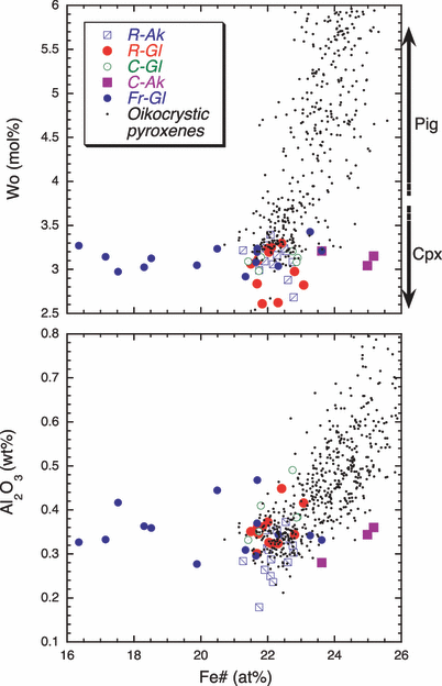
Compositions of high-pressure polymorphs of MgSiO3 in the shock vein with those of oikocrystic low-Ca pyroxenes in Y-000047. Cpx, Ca-poor clinopyroxene, which is the host phase of the shock vein. Pig, pigeonite; R-Ak, rim akimotoite; R-Gl, rim glass; C-Gl, center glass; C-Ak, dendritic akimotoite in the vein center; Fr-Gl, framboidal glass.
The several central portions in the main shock vein form framboidal glass aggregates of 2–3 μm in each size (Fr-Aggr in 1, 2, or Fr-Gl in Fig. 2b), and the other central portions show dendritic textures (C-Ak in 2, 3). Their modal abundances are commonly low (a few modal%). Framboidal aggregates (Fr-Aggr in 1, 2) in the vein center are the most magnesian with the composition of En81.4–74.6Fs15.5–22.3Wo3.1–3.2, while dendrites in the vein center (C-Ak in 2, 3) are the most ferroan with the composition of En74.6–72.7Fs22.3–24.2Wo3.1–3.2 among the high-pressure polymorphs of the pyroxenes in the shock veins. Except different Fe-Mg variation of framboidal aggregates and dendrites in the vein center from those of hostic oikocrystic clinopyroxene in the poikilitic area, minor element compositions of framboidal aggregates and dendrites have similar compositions with those of hostic oikocrystic clinopyroxene in the poikilitic area (Table 1, Fig. 4).
MicroRaman Spectroscopy of the Shock Vein
Polymorphs of magnesian low-Ca pyroxenes in shock veins as well as the hostic low-Ca pyroxenes in the poikilitic area are studied using microRaman spectroscopy (5, 6). Magnesian low-Ca pyroxenes in the host phase is a typical clinopyroxene (P21/c), as the wave numbers of 600–800 cm−1 and 300–450 cm−1 have commonly doublet bands, and the band of <300 cm−1 is about 230 cm−1 in Fig. 5 (Wang et al. 2001). The obtained space group is consistent with that obtained from the electron backscatter diffraction (EBSD) method (Mikouchi and Kurihara 2008). The host oikocrystic magnesian Ca-poor clinopyroxene used to be orthopyroxene, and the orthopyroxene transformed into clinopyroxene during the shock metamorphism (e.g., Stöffler et al. 1991).
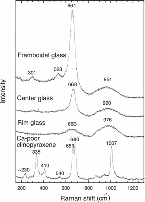
Raman spectra of the three kinds of MgSiO3 glasses in the shock vein and Ca-poor clinopyroxene (P21/c) of the host phase.
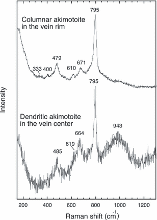
Raman spectra of akimotoites, high-pressure polymorphs of MgSiO3, are shown: dendrites in the vein center and columnar phase in the vein rim. Dendritic akimotoite in the vein center includes Raman bands of the surrounding pyroxene glass of 664 and 943 cm−1.
The Raman spectra of columnar shaped crystals in the shock vein (Col in Fig. 1d and R-Ak in 2, 3) have 333, 440, 479, 610, 671, and 795 cm−1 in the order (Fig. 6). The intensity of 660–670 cm−1 in center glassy phase is stronger than that of rim glassy phase. Two kinds of interfiling glass occur in the vein rim (R-Gl in Fig. 2) and the vein center (C-Gl in Fig. 2).
The Raman spectra of the framboidal aggregates (Fr-Aggr in Fig. 2a) have peak of 301, 528, 661, and 951 cm−1 (Fig. 5). The Raman spectra of the interior two glassy phases have commonly two broad peaks in the similar wavelength with the similar width: 663 and 976 cm−1 for the rim glass and 668 and 960 cm−1 for the center glass. The broad band of about 960–980 cm−1 commonly ranges from about 800 to about 1000 cm−1. The Raman shift of the 951 cm−1 broad band in the framboidal aggregates is very similar to those of two glassy phases (Fig. 5). Dendritic fine-grained crystals in the vein center (C-Ak in 2, 3) have Raman shift of 485, 619, 664, 795, and 943 cm−1 in the order (Fig. 6).
Discussion
Phase Identifications in the Shock Vein of the Y-000047 Lherzolitic Shergottite
Columnar Phase
The Raman spectra of columnar crystal in the vein rim in Fig. 6 are quite different from those of pyroxene glasses in Fig. 5. Ferroir et al. (2008) showed the Raman spectra of akimotoite in the Tenham L6 chondrite, a high-pressure polymorph of MgSiO3 with ilmenite structure, with the peak of 342, 407, 477, 614, 672, and 796 cm−1. Ohtani et al. (2004) showed the Raman spectra of akimotoite as 340, 403, 474, 612, about 675, and 795 cm−1. Kimura et al. (2003) have also showed that the major peak of the Raman spectra of akimotoite in the Y-75267 H6 chondrite is 336, 480, 615, and 798 cm−1. The strongest peak of their spectra is commonly about 800 cm−1. The Raman spectrum of the columnar crystals in the vein rim is very similar to akimotite shown by Ferroir et al. (2008), Ohtani et al. (2004), and Kimura et al. (2003). Thus columnar phase is akimotoite. Mikouchi and Kurihara (2008) also found that columnar crystals in the shock vein in Y-000047 are akimotoites from the EBSD method.
Interfiling Glasses and Framboidal Phase
The Raman spectra of vitrified framboidal glass aggregates in the vein center, and those of two glassy phases in the vein center and vein rim are shown with that of the host clinopyroxene in Fig. 5. The Raman spectrum of center glass in Fig. 5 is identical to the (Mg,Fe)SiO3 pyroxene glass in the Suizhou L6 chondrite (in fig. 7C by Chen et al. 2004), suggesting that the center glass is pyroxene glass. While the intensity of the band about 660–670 cm−1 for the rim glass is lower than that of center glass, the intensity of 960–980 cm−1 is similar to each other. Raman spectra of pyroxenes have two representative peaks of about 660 cm−1 and about 1000 cm−1, and the Raman shift of about 660 cm−1 corresponds to the symmetric stretching vibration of Si-O-Si bond in Si2O6 chains (Wang et al. 2001). Therefore, the lower intensity of the 663 cm−1 band in rim glass suggests that the pyroxene chain is more imperfect than that of the center glass.
On the other hand, the broad band of about 951 cm−1 in the Raman spectrum of framboidal aggregates is very similar to center and rim glass (Fig. 5), and the band of about 661 cm−1 is much sharper than those of two pyroxene glasses. There are also two additional bands of 301 and 528 cm−1 in the spectra, which are not observed in pyroxene glass in vein center and vein rim. These two bands seem to correspond to clinopyroxene spectrum (Fig. 5), suggesting that the framboidal aggregates have pyroxene-like crystal structure although the bonding between pyroxene chains may be immature. Mikouchi and Kurihara (2008) also found that framboidal aggregates in the shock vein in Y-000047 are amorphous phase from the EBSD method.
Their intensities of about 660 cm−1 are different among these three kinds of glasses: the intensity decreases in the order of framboidal glass aggregates, glass in the vein center, and glass in the vein rim, suggesting that they may have stronger tendency to form pyroxene chains in this order. Thus, the different intensities of about 660 cm−1 among three pyroxene glasses may reflect the different cooling rates: the slowest cooled framboidal glass aggregates in the vein center, the intermediately cooled glass in the vein center was intermediate, and the fastest cooled glass in the vein edge.
The Raman shift of about 1000 cm−1 corresponds to the symmetric stretching vibration of Si-O bond in SiO4 tetrahedra (Wang et al. 2001), and the three kinds of glasses have the similar broad peaks on about 1000 cm−1. This suggests that crystal structures of pyroxene with long-range order are more difficult to form than that of SiO4-tetrahedral chains observed in about 660 cm−1 under the rapidly cooled condition.
Dendritic Phase
The most intense band is 795 cm−1 for dendritic fine-grained crystals in the vein center, and the two peaks of 664 and 943 cm−1 may show contamination from the surrounding pyroxene glass. This spectrum is similar to that of columnar akimotoite in the vein rim. The spectrum is the most similar to that of akimotoite coexisting with pyroxene in the Sixiangkou L6 chondrite shown by Zhang et al. (2006). Therefore, dendritic fine-grained crystals in the vein center are also akimotoite (Fig. 6). The constituent phases of the main shock vein in the area in Fig. 2a is thus schematically summarized in Fig. 2b.
Formation of the Shock Vein and Its Crystallization
Akimotoites
Two processes for crystallization of akimotoites have been considered (Zhang et al. 2006). One is solid-state phase transition observed from pyroxene in Tenham (Tomioka and Fujino 1997), Sixiangkou (Zhang et al. 2006), and Y-791384 L6 chondrites (Ohtani et al. 2004), and their akimotoites commonly have Fe# = 21. The solid-state phase transition model from high-pressure clinopyroxene to akimotoite has been also modeled based on the shear stress from the crystallographic consideration (Tomioka 2007). Another is the metastable crystallization of akimotoites from shock-produced melt in Acfer 040 (Fe# = 5.5, Sharp et al. 1997), Tenham (Fe# = 12, Xie et al. 2006b), and Umbarger (Fe# = 11, Xie and Sharp 2004) L6 chondrites. These akimotoites from the above references have been commonly found from equilibrated L6 chondrites, suggesting that the composition of host phase are nearly identical. As the Fe# of low-Ca pyroxenes for L6 chondrites is 19–22, the solid-state phase transition from low-Ca pyroxene to akimotoite preserved the original composition, although the shock-produced melt crystallized more magnesian and variable Fe#s than that of host phase low-Ca pyroxene.
Texturally, columnar akimotoites in the vein rim in the shock vein of Y-000047 seem to replace parts of the host Ca-poor clinopyroxene (Fig. 2d). The solid-state phase transition is classified into two types based on its transformation mechanism, displacive phase transition and reconstructive phase transition. The displacive transition is rapid process, and the reconstructive transition is sluggish process (e.g., Putnis 1992). The mechanism of the phase transition of orthopyroxene to Ca-poor clinopyroxene is classified into displacive transition (e.g., Putnis 1992). We suggest that the rim akimotoite did not form from solid-state phase transition of orthopyroxene during the increase of pressure and temperature, but it transformed from the Ca-poor clinopyroxene already inverted from orthopyroxene under the sobsolidus condition near the metastable liquidus temperature of pyroxene during the cooling of the shock vein (Fig. 7).
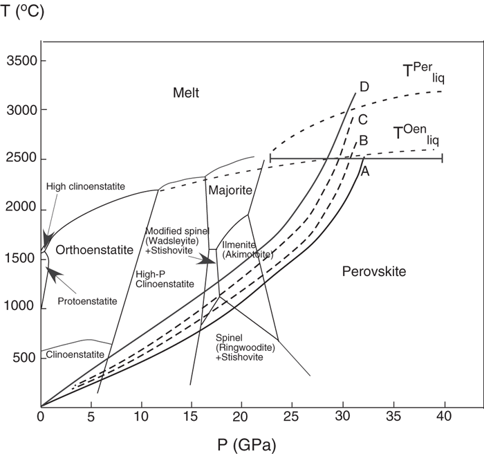
An equilibrium phase diagram of MgSiO3 polymorphs based on Gasparik (1990a, 1990b) and Hirose et al. (2001) with the possible trajectories for the T–P history of the shock vein in Y-000047. The trajectories A–D indicate formation of columnar akimotoites in the vein rim, pyroxene glass in the vein rim, pyroxene glass in the vein center, and framboidal aggregates and dendritic akimotoites in the vein center, respectively. The peak shock pressure in the figure is 31.5 GPa of the median in the possible variation in the range of 23–40 GPa, and the range is indicated as a horizontal bar. TPerliq, liquidus temperature of perovskite phase; TOenliq, metastable liquidus temperature of orthoenstatite.
Generally, akimotoite is only subsolidus phase among MgSiO3 high-pressure polymorphs. The other two sub-solidus regions are known to be mixtures of wadsleyite (β-Mg2SiO4) and stishovite at lower pressure, and mixtures of ringwoodite (γ-Mg2SiO4) and stishovite at lower temperature. The liquidus phases with MgSiO3 composition are known to be perovskite phase at higher pressure, and majorite at higher temperature (e.g., Gasparik 1990a,b). In the Y-000047 lherzolitic shergottite, Fe#s of center akimotoite consisting of fine-grained dendritic crystals are slightly more ferroan than those of the host oikocrystic low-Ca pyroxenes (Table 1; Fig. 4). Therefore, the crystallization of dendritic akimotoite rapidly occurred from super cooled shock fractionated melt under the metastable condition.
Framboidal Aggregates
Framboidal glass aggregates in the vein center are more magnesian in composition and have wider Fe–Mg compositional range than the host oikocrystic low-Ca pyroxene (Table 1; Fig. 4). These suggest that they are vitrified from a high-pressure polymorph of MgSiO3 crystallized from shock melt. According to the static high-pressure experiments using MgSiO3, majorite and akimotoite are quenchable when the charge changes from the condition of the high pressure and high temperature to atmospheric pressure and air temperature (Ringwood and Major 1971; Kawai et al. 1974), although majorite phases are never identified from the shock vein in Y-000047. However, perovskite phase, post-perovskite phase, and high-pressure clinoenstatite are difficult to be quenched under the air condition and tend to change amorphous under the atmospheric condition (e.g., Wang et al. 1992; Sharp et al. 1997; Shinmei et al. 1999; Murakami et al. 2004).
The crystal structure of both the perovskite phase and post-perovskite phase is orthorhombic, and the framboidal aggregate may be possible morphology for both phases. However, the post-perovskite phase is stable more than approximately 120 GPa at high temperature (more than 1800 °C). The extremely high pressure may not be generally probable for the shock vein formation in meteorites, because the pressure more than 75 GPa may cause shock melting of the whole meteorite (e.g., Stöffler et al. 1991). Based on the above discussion, we conclude that framboidal glass aggregates were perovskite phase before the vitrification.
Estimation of Maximum Temperature and Pressure, and Its Cooling History
The crystallization sequence is interpreted based on the high-pressure phase diagram of MgSiO3 (Gasparik 1990a, 1990b) with modified phase boundaries of majorite-akimotoite-provskite (Hirose et al. 2001) and the compositions of these phases (Fig. 7). The maximum shock pressure for shergottites has been estimated to be 30–43 GPa (Stöffler et al. 1986). Fritz et al. (2005) obtained the peak shock pressure for the Y-793605 lherzolitic shergottite to be 40–45 GPa based on the micro-Raman spectroscopy of maskelynite. When a rock experiences an impact shock, the maximum shock pressure has been estimated to be nearly homogeneous inside of the whole rock due to the propagations and reflections of shock waves (e.g., Sharp and DeCarli 2006), except shock melt pockets which melted by local concentration of shock wave. Therefore, the peak shock pressure of maskelynite in non-poikilitic area in the Yamoto 00 lherzolitic shergottites may be nearly identical with that of the shock vein in Y-000047. The mineralogy and petrology of Y-793605 is similar to those of the Yamoto 00 lherzolitic shergottites based on our observation and Mikouchi and Kurihara (2008). The shock degree of Y-793605 is also similar to that of Y-000047, although the degree of undulatory extinction of olivines in Y-793605 is slightly higher than that of the Yamato 00 lherzolitic shergottites. Then the shock pressure would be approximately 40 GPa for the Y-000047 lherzolitic shergottite. The estimation of the peak shock pressure is based on the shock recovery experiments. Sharp and DeCarli (2006) pointed out that the shock pressure in nature based on experiments has been overestimated due to significantly longer shock pulse (several seconds) and more sluggish cooling time (up to 1 s) in nature than those in shock recovery experiments (∼10 μs shock pulse), and they roughly estimated that the peak shock pressure is much lower (∼up to half) than those expected from experiments. They also showed that the equilibrium phase diagram based on static high-pressure experiments rather than the results from shock recovery experiments is available for the understanding of the P–T history of shock vein in meteorites. The equilibrium phase diagram shows that more than 23 GPa is necessary for the formation of perovskite phase (Fig. 7). Taking this discussion into consideration, we conclude that the shock pressure of 23–40 GPa is possible shock pressure range for the Y-000047 lherzolitic shergottite. In Fig. 7, we showed the median with the possible errors.
In situ experiments of majorite–akimotoite–perovskite phase transition (Hirose et al. 2001) show that solid-state phase transitions occur among the three minerals. However, the phase transition into perovskite phase should be classified into reconstructive transition, which is sluggish process. Therefore, only clinoenstatite may have transformed from the host orthopyroxene during this transient state. This may bring an assumption that the host orthopyroxene in the shock vein in the poikilitic area melted at the metastable liquidus boundary of pyroxene indicated as TOenliq in Fig. 7, and the solidification of the shock vein occurred after the peak shock pressure and temperatures (Fig. 8).
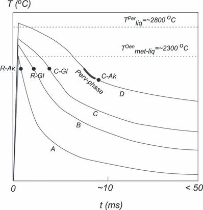
A schematic illustration showing the solidification sequence of MgSiO3 high-pressure polymorphs in the shock melt vein in Y-000047. Trajectories A–D correspond to those in Fig. 7, and A shows the cooling history of the area formed columnar akimotoite in the vein rim (R-Ak), B vein-rim glass (R-Gl), C vein-center glass (C-Gl), D framboidal aggregates of perovskite phase (Perv-phase) and dendritic akimotoite (C-Ak) in the vein center. Points on trajectories A–D show the solidification period of R-Ak, R-Gl, C-Gl, and C-Ak, respectively, and a thick bar on D Perv-phase. TPerliq, liquidus temperature of perovskite phase at 27 GPa (∼2800 °C, see Fig. 7); TOenliq, metastable liquidus temperature of orthoenstatite at 27 GPa (∼2300 °C, see Fig. 7).
The duration of the subsequent cooling for the solidification, which is defined as the quench time after the maximum shock temperature, is estimated to be much longer (∼0.05 s) in the vein center than those (<0.01 s) in the vein edge for the Tenham L6 chondrite (e.g., Sharp and DeCarli 2006). The cooling rate in the vein center may be slower (∼104 °C s−1) than that (∼105 °C s−1) in the rim. As the shock vein in the Y-000047 lherzolitic shergottite is much thinner, the cooling may be much more rapid (<0.05 s) as be illustrated in Fig. 8. Additionally, it has been assumed that the maximum shock temperature in the vein rim was lower than that in the vein center (e.g., Xie et al. 2006a, 2006b). This suggests that the vein edge did not melt, indicated as A in Fig. 7 and the vein center melted, indicated as B–D in Fig. 7. Then the maximum pressure and temperature in the vein center are estimated to be 23–40 GPa and more than 3000 °C, respectively (Fig. 7). During the cooling time of <0.05 (s), the peak shock pressure of 23–40 GPa was kept, suggesting that the time scale of the pressure pulse is sufficiently longer than the cooling time scale as there is no evidence of the pressure release during the crystallization in the shock vein (e.g., Sharp and DeCarli 2006).
The formation sequences of the constituent phases in the shock vein are summarized from the texture and phase relationship, and schematically shown in Fig. 8: first, an impact shock has produced both a melt vein and ambient Ca-poor clinopyroxene from orthopyroxene in the poikilitic area. Second, the akimotoite at the vein rim metastably formed under the subsolidus condition (A in Fig. 8). Third pyroxene glass solidified in the vein rim (B). Fourth pyroxene glass in the vein rim (C). Finally, framdoidal perovskite phase (D) and metastably dendritic akimotoite (D) crystallized by the fractional crystallization from residual melt in the vein center. The formation for the two pyroxene glasses in the vein rim and vein center were nearly contemporaneous, and the crystallization timing of dendritic akimotoite and provskite-phase were also contemporaneous. The liquidus temperature of perovskite phase seems to be approximately 2800 °C, and the solidification temperature of akimotoites and glasses is estimated to be much lower according to the equilibrium phase diagram in Fig. 7. The crystallization temperature of perovskite phase is much lower than the equilibrium liquidus temperature of perovskite phase (∼2800 °C) due to the supercooling. And the subsolidus-cooling rate after vitrification was different; glass in the vein center was slower than that in the vein rim. The identical composition of rim akimotoite with the host Ca-poor clinopyroxene suggests that orthopyroxene with the (Mg0.8,Fe0.2)SiO3 composition congruently melted under the metastable condition.
Thin shock veins tend to occur in the poikilitic area as can be seen in Y-000047 and Y-000097 (Fig. 1). The reason why the thin shock veins occur only in poikilitic area but not in non-poikilitic area may be attributed to the different shock responses among the two areas: the mafic orthopyroxene in the poikilitic area is brittle and the feldspathic non-poikilitic area is ductile.
Importance of the Simple Shock Vein from the Martian Meteorite
Shock melt vein in chondrites which occur in equilibrated ordinary chondrites, much in L6 chondrites (e.g., Sharp and DeCarli 2006), is the chondritic melt producing a lot of high-pressure polymorphs of olivine, low-Ca pyroxene, high-Ca pyroxene, and plagioclase from the melt. High-pressure phases have been found from the shock veins in pyroxenes and plagioclase of the Zagami basaltic shergottite (Langenhorst and Poirier 2000). Compositions of akimotoites and vitrified perovskites from Y-000047 are much more magnesian than those from Zagami (Fe# = 32 for akimotoites and 41–73 for vitrified perovskites). Most of high-pressure polymorphs of pyroxenes crystallized from shock melt produced by the melting of the mixtures of pyroxene and other minerals such as olivine and plagioclase. On the other hand, the fact that the shock vein in Y-000047 only produced from oikocrystic Ca-poor pyroxene should be quite unique, making simply magnesian Ca-poor pyroxene melt. The simple shock textures in Y-000047 would potentially play an important role in the understanding of the formation of the high-pressure polymorphs of MgSiO3.
Summary
We reported high-pressure polymorphs having an orthopyroxene composition in a shock vein of the lherzolitic shergottite, Y-000047. The shock vein shows extraordinary simple textures formed only in an oikocrystic single crystal of Ca-poor magnesian pyroxene, thus the interpreted results for the crystallization will play an important role in the high-pressure research.
Acknowledgments— We are grateful to Prof. M. Kimura at Ibaraki University for the identification of pyroxene glasses from Raman spectra. The study was much improved by constructive reviews of Drs. A. H. Treiman and N. Tomioka, and an anonymous referee. This research is partly supported by the NIPR research project, P-8 (Evolution of the Early Solar System Materials).
Editorial Handling—Dr. Allan Treiman


