In Vitro Comparison of Two Techniques for Suture Prosthesis Placement in the Muscular Process of the Equine Arytenoid Cartilage
Abstract
Objective— To compare in vitro the load necessary for a partial and complete rupture of the muscular process arytenoid cartilage when a suture prosthesis is positioned by a bone trocar versus a trocar point needle and to compare failure mode.
Study Design— Experimental using cadaver specimens.
Sample Population— Larynges from 18 Thoroughbred race horses, aged 2–20 years.
Methods— Arytenoid cartilages were separated randomly into 2 groups: group 1—suture prosthesis inserted directly through the muscular process using a curved trocar point needle and group 2—suture passed through a hole predrilled with a 3 mm bone trocar. Distracting force (constant rate, 1 mm/s) was applied to the suture until failure of the muscular process. Partial failure load, maximum load at complete failure, and force–time curve were recorded. Each arytenoid cartilage was examined, radiographed, and classified as having a linear or curved failure plane.
Results— No significant differences in mechanical test variables were detected. Failure mode followed the fissures occurring at the beginning of failure and then followed the tension axis. Significantly more linear failures occurred in group 2 (trocar) and more curved failures occurred in group 1 (needle).
Conclusion— Use of a bone trocar for tunneling through the muscular process may reduce fissure formation.
Clinical Relevance— Use of bone trocar to create a hole in the muscular process of the arytenoid cartilage for suture passage in laryngoplasty may reduce fissure formation and decrease the risk of cartilage failure from suture pullout.
INTRODUCTION
LARYNGOPLASTY, by insertion of a suture prosthesis to achieve arytenoid cartilage abduction, is effective for treatment of exercise intolerance and inspiratory stridor caused by laryngeal hemiplegia, by improving airflow through the upper respiratory tract.1–4 Prosthesis failure occurs and is recognized by partial or complete collapse of the arytenoid cartilage.5 Boswell et al6 and Dean et al7 reported that partial failure of the muscular process cartilage is likely the cause of relaxation in the position of the arytenoid cartilage after laryngoplasty. Further, Dean et al7 reported no significant effect of age on cartilage retention of the prostheses. Different surgical variables, including the method of prosthesis passage through the muscular process of the arytenoid cartilage, have been compared in vitro without demonstrating a significant difference between variables related to the resistance of the arytenoid cartilage to failure.8 Failure was typically characterized by partial failure of the muscular process, defined by an initial load–displacement peak followed by increased cartilage retention strength before complete failure occurred.8
For 15 years, one of the authors (Desbrosse) has used a bone trocar to tunnel through the muscular process of the arytenoid cartilage before suture placement. The intent of this technique was to reduce the likelihood of cartilage microfractures and thus reduce the likelihood of cartilage failure. Accordingly, we hypothesized that creation of a tunnel in the muscular process with a bone trocar would provide improved holding power of a suture prosthesis. To test this hypothesis we compared: (1) in vitro, the loads necessary for partial and complete failure of suture prostheses inserted through the muscular process of the arytenoid cartilage using a needle or by creating a tunnel with a trocar and (2) radiographic images of arytenoid cartilages after failure to further characterize failure mode.
MATERIALS AND METHODS
Specimens
Eighteen larynges from Thoroughbred racehorses (aged 2–20 years) were collected at necropsy and immediately frozen at −20°C; larynges were not individually identified. After thawing at room temperature for 24 hours, left and right arytenoid cartilages were separated from the intrinsic musculature and disarticulated to allow standardized insertion of a prosthesis through the muscular process. Immediately after dissection, each arytenoid was placed between abdominal sponges moistened with saline (0.9% NaCl) solution. Arytenoid cartilages were numbered 1L—18L (left arytenoids) and 1R—18R (right arytenoids) before being randomly assigned to 2 groups, with each group having an equal number of left and right arytenoids. The mean horse age was not significantly different between groups (t-test=0.38, P=.71).
Implantation Technique
Each arytenoid cartilage had a 4-mm diameter hole drilled to allow passage of a screw with 2 rigid plastic disks that grasped the cartilage to provide maximum stability for mounting in the mechanical testing device. This hole, positioned near the cartilage border ventral to the muscular process, was located by the mid-point of the line, joining the dorsal crest and the vocal process (Fig 1). In pilot tests, this location resulted in consistent failure of the muscular process during suture pull-out rather than arytenoid cartilage failure.
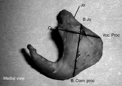
Arytenoid cartilage, medial view. Position of the drill hole for attaching cartilage to the mechanical testing apparatus. Jo, cricoarytenoid joint; B Jo, base of the cricoarytenoid joint; B. Corn.proc, base of the corniculate process; Cr, dorsal crest; Voc. Proc, vocal process.
Suture prosthesis (braided polyester 7 metric, Surgidac ND, Tyco, Lure cedex, France) was passed through the muscular process by 1 of 2 techniques. Suture location in the muscular process was always 1 cm distal to the muscular insertion of the cricoarytenoideus dorsalis muscle with a rostromedial–caudolateral orientation (parallel to the cricoarytenoid articulation [CAA]; Fig 2). In group 1, the prosthesis was inserted using an eyed, curved needle with a trocar point (1/2 circle no. 2; Acufirm, München, Germany), whereas in group 2, a hole was made through the muscular process using a bone trocar (3 mm diameter, 13 mm length, Collin, Paris, France) inserted by a twisting action, and then the suture was passed directly through the hole.
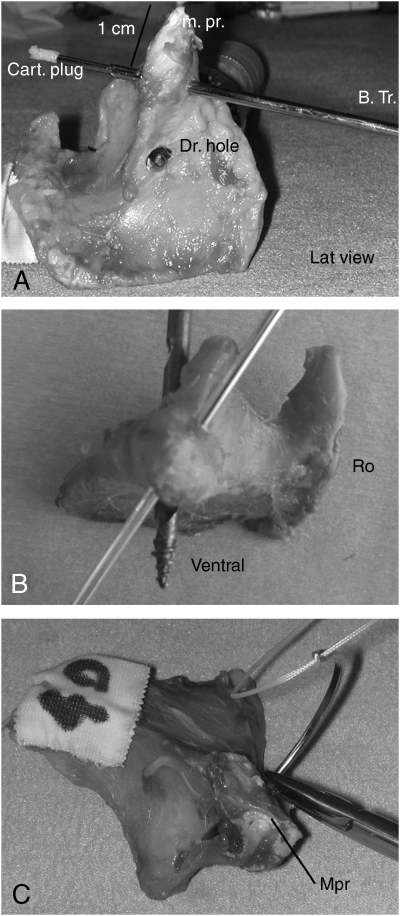
Arytenoid cartilage specimen. (A) Lateral view. Use of a trocar to create a hole in the muscular process. B. Tr., bone trocart; Dr. hole, drill hole; m.pr., muscular process; Cart. plug, cartilaginous plug. (B) View from above the muscular process. (C) View from above the muscular process showing insertion of a trocar point needle through the muscular process (m.pr.).
Mechanical Testing
Specimens were mounted in a testing device (Fig 3) that consisted of a stand fitted with a central screw column and 2 supporting uprights to which a mobile crosshead (Andilog, BP 80, Chaville, France) and digital force gauge (Andilog) were attached. The force gauge supported a stirrup-like device made from 2 orthopedic plates between which passed a bolt with 2 disks of rigid rough plastic for grasping the arytenoid cartilage and to minimize deformation.
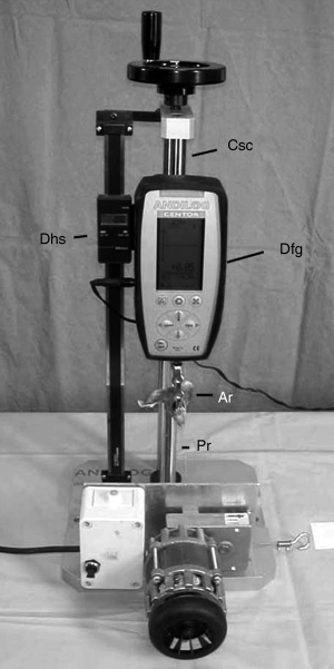
Mechanical testing apparatus. Csc, central screw column; Dfg, digital force gauge; Dhs, digital height scale; Ar, arytenoid; Pr, prothesis.
Arytenoid specimens were chosen randomly from each group and mounted in the testing device (Fig 4). The suture prosthesis was then passed through the muscular process and a loop was formed by tying a square knot followed by 4 throws. The length of the suture loop was constant (25 cm) for each arytenoid and the base of the loop was passed around the fixed base of the device. A cylindrical worm gear crank (Andilog) was manually operated to move the crosshead and distract the arytenoid at a constant rate of 1 mm/s until cartilage failure. To assure a constant and regular movement, the same operator turned the worm gear crank (1 turn every 4 seconds). The moving speed of the crosshead was controlled by a digital height scale.
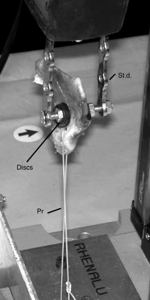
Close-up view of attachment of arytenoid cartialge to the mechanical testing apparatus. St.d., stirrup-like design; Disks, rigid rough plastic disks to grip cartilage; Pr, prosthesis.
Force was recorded at partial failure load (corresponding to a decrease in load of at least 5%), the maximum load at failure, and a force–time curve generated. The digital height scale attached to the crosshead measured displacement, and therefore the degree of deformation at failure.
Radiographic Assessment
After completion of mechanical tests, each arytenoid cartilage was radiographed. A radio-opaque marker (very thin steel wire) was introduced through the center of the failure plane until it reached the center of the initial location of the prosthesis. This marker allowed easy observation of the center of the failure plane. Then, arytenoid specimens were placed on an aluminum filter (to prevent X-ray diffraction), positioned on a digital radiograph film so that the central x-ray beam was parallel to the CAA and therefore parallel to the initial axis of the prosthesis. Radiographic images were analyzed by classifying the shape of the failure plane using 1 of 2 categories: D, linear rupture plane (Fig 5A); C, curved rupture plane (Fig 5B).
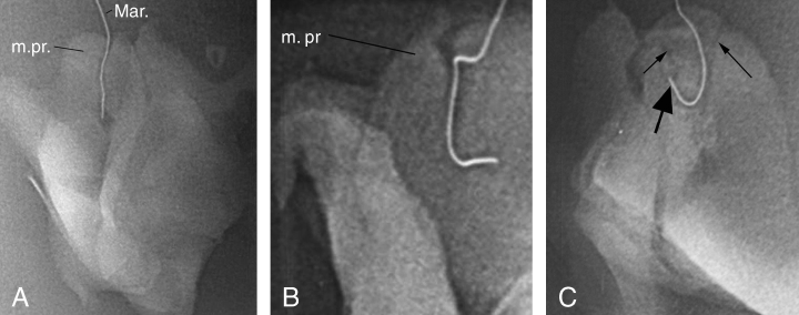
(A) Radiographic projection of the arytenoid showing a linear failure plane. M.pr., muscular process; Mar, Radio-opaque marker. (B) Curved failure plane. (C) Fissures (small arrows) and origin of the prosthesis (large arrow).
Statistical Analysis
Data were described using mean±SD for continuous variables and percentages for categorical variables. A Wilcoxon's signed-rank test was used for comparison of the mean load at the point of partial failure and the mean maximal tension at the moment of failure between groups. The χ2 test was used to compare the percentages of linear rupture between groups. Statistical significance was determined at P<.05. All statistical analysis was performed by using the R sofware package.9
RESULTS
Mechanical Tests
Thirty-two arytenoid cartilages failed at the muscular process, 2 failed at the knot (knot slippage), and 1 failed at the cartilage screw hole. In 1 specimen, test values were not recorded because of an electronic problem. In 16 of 32 specimens (8 each from groups 1 and 2) there was partial failure of the muscular process followed by an increase in resistance before complete failure. Partial failure was characterized by 2 peaks in the load curve, a short peak, and then a higher one (Fig 6A). In other specimens, partial failure was followed more or less simultaneously by complete failure without an increase in the resistance (Fig 6B). The maximum load at failure was therefore considered equal to the load at the time of partial failure. The mean load at the point of partial failure was 11.79±3.47 kg for group 1 (needle) and 13.33±3.36 kg for group 2 (trocar). The mean maximal tension at failure for group 1 (14.13±2.35 kg) was not significantly different from group 2 (14.31±2.66 kg).

Load versus time curves. (A) Partial failure of the muscular process. (B) Complete failure after partial failure.
Radiographic Evaluation of Failure Mode
In group 1 (needle), 2 specimens were classified as linear failures (category D) and 14 as curved (category C). Two specimens were excluded before being tested: 1 because of knot slippage and 1 because of difficulty in perfectly introducing the marker into the fracture plane. In group 2 (trocar), 11 specimens had linear failure and 3 curved. Five were excluded: 2 because of knot slippage, 1 because of cartilage rupture at the level of the screw hole, and 2 because the shape of the failure plane had a low angle, making classification difficult. The difference in failure mode between groups was significant (P=.0003).
DISCUSSION
Although there was no significant difference in load at failure, failure mode was different between specimens where the prosthesis was inserted by a trocar point needle and those inserted through a predrilled hole. Intuitively, use of a trocar pointed needle versus a trocar to create a hole for suture passage might be expected to create more microfissures in the muscular process, because the latter technique removes a plug of cartilage by a cutting action, whereas the trocar point needle compresses the surrounding cartilage to create a space for the suture. Indeed, we observed more microfissures in specimens where a trocar point needle was used than in those where a trocar was used. The bone trocar is used for performing bone biopsies because of its capacity to pass through the bone in a clean and non-traumatic manner. It was easy to tunnel through the muscular process with the bone trocar by way of a simple rotary action while applying a moderate degree of pressure.
A tunneling technique using a 16 G hypodermic needle to facilitate prosthesis passage is used by some surgeons. Boswell et al6 reported no significant difference in failure load in muscular processes where a prosthesis has been inserted either directly with a trocar needle or after tunneling with a 16 G hypodermic needle. In that report and in ours, the load at failure was significantly higher than the load needed for surgical abduction of an arytenoid cartilage. It is likely that the nature of load application is different in vitro and during surgery. Moreover, the load applied when there was partial rupture (needle, 11.8 kg; trocar, 13.3 kg) was 4-fold higher than the load needed to achieve arytenoid abduction during laryngoplasty in vivo.6 Forces acting on the arytenoid cartilage in vivo that may predispose to failure by partial rupture of the muscular process are likely cyclical in nature and thus more difficult to demonstrate in vitro.
Radiography is widely used in industry, particularly in the aeronautical sector, to detect fissures present in materials and to test resistance to long-term use. Although we radiographed our specimens, we found it difficult to fully define the configuration of the failure plane because it and the fissures were not contained in a single plane. Imaging modalities like magnetic resonance imaging or computed tomography with subsequent 3-dimensional reconstruction would have facilitated interpretation of failure mode patterns. However, by using a radio-opaque marker (a very thin steel wire) inserted through the center of the failure plane from the extremity of the muscular process to the prosthesis insertion site, we were at least able to localize the center of the failure plane.
When examining some arytenoid cartilage specimens after failure, we observed small fissures (Fig 5C) that seemingly initiated the plane of failure in a direction different from the axis of traction whereas for some specimens, failure occurred in a plane perpendicular to the traction plane. Intuitively, we would have anticipated failure to have occurred along the axis of traction, so it seems logical that when microfissures were present that the failure plane originated from these defects, away from the direction of traction. Fissures decrease material resistance to long-term use. Significantly fewer curved failure planes occurred when prosthesis passage was through the trocar hole, whereas curved failure planes occurred significantly more often in specimens (14 of 16) when a needle was used for suture passage. Fissures in the muscular process were more commonly observed in specimens where a needle was used. We used a 7 metric suture, the maximal size adapted to the needle but not to the trocar. It is possible that use of a suture size that approximated the trocar hole would have resulted in fewer failures in these specimens, by distributing the surface forces on the suture more evenly.
We conclude that use of a bone trocar for tunneling through the muscular process during laryngoplasty decreases the risk of fissure formation in the arytenoid cartilage. Fissure occurrence appears more unpredictable when the muscular process is directly perforated by a trocar point needle. Intuitively, suture passage without fissure formation should decrease the risk of cartilage failure. Clinically, both prosthesis insertion techniques are used but because the prevalence of cartilage failure with either technique is unknown, it is not reasonable to make a specific recommendation for clinical use based solely on monotonic in vitro testing observations.
ACKNOWLEDGMENT
The authors thank Pr. Nathalie Crevier-Denoix for her assistance with the anatomic aspect of the study, Drs. Claire Laugier and Nathalie Foucher for collecting the larynges, and Dr. Hameline Virevialle for her collaboration in the tests.


