Volume 70, Issue 5 pp. 886-903
Original Article
Full Access

Wavefield simulation of fractured porous media and propagation characteristics analysis

Kang Wang

Corresponding Author

Kang Wang

State Key Laboratory of Coal Resources and Safe Mining, China University of Mining and Technology (Beijing), Beijing, 100083 China

Email: [email protected]

Search for more papers by this author
Suping Peng

Suping Peng

State Key Laboratory of Coal Resources and Safe Mining, China University of Mining and Technology (Beijing), Beijing, 100083 China

Search for more papers by this author
Yongxu Lu

Yongxu Lu

State Key Laboratory of Coal Resources and Safe Mining, China University of Mining and Technology (Beijing), Beijing, 100083 China

Search for more papers by this author
Xiaoqin Cui

Xiaoqin Cui

State Key Laboratory of Coal Resources and Safe Mining, China University of Mining and Technology (Beijing), Beijing, 100083 China

Search for more papers by this author
First published: 28 March 2022

ABSTRACT

Most fractured reservoirs are two-phase media, that is, mixture of solid matrix and void. It contains rock skeleton and fractures or pores filled with oil, gas and water. These fractures are the channels of oil and gas storage and migration. In two-phase media, the interaction between the fluid and solid phases will further complicate the seismic wave propagation. Natural fractures are typically irregular in shape, thereby causing difficulties in the exploration of fractured reservoirs. Therefore, the key to the prediction of fractures is to study the equation of motion of seismic waves and energy distribution of seismic waves at the fracture interface. To derive the propagation law for complex irregular shape fractures in two-phase media, we combined the stiffness matrix of the media with linear slip theory and derived a numerical simulation scheme. The simulation scheme considers the fractures in the two-phase media to be in any direction. In addition, seismic wave energy distribution at the fracture interface was obtained. The linear slip boundary condition was introduced into the conventional Zoeppritz equation, and a modified Zoeppritz equation was proposed for two-phase fractured media. The reflection and transmission due to the fracture interface were considered in the new equation, thereby making the equation more flexible. Using the new numerical simulation scheme, we analysed the elastic waves produced by the linear slip fracture interface in two-phase media and provided the long-term stability results of the new scheme. Moreover, we provided the relationship between the reflection and transmission coefficients of the linear slip fracture interface and the incident angle and compliance in two-phase media using the new Zoeppritz equation. The results show that the reflection wave of two-phase fractured media can be divided into wave impedance and fracture parts to accurately describe the properties of underground rocks.

INTRODUCTION

Fractures are one of the primary targets of hydrocarbon exploration, as they are the storage spaces and connecting channels of oil and gas. The anisotropy caused by fractures can cause the dispersion of seismic wave velocity, thereby leading to inaccurate seismic imaging (Thomsen, 1995; Bakulin et al., 2000). The purpose of numerical simulation is to study seismic wave propagation characteristics, which can be used to evaluate the relationship between seismic waves and fractured media. Virieux (1986) first proposed the standard staggered-grid finite-difference method, which considers the speed and accuracy of calculation, and is currently the most commonly used method for forward modelling.

While introducing fracture, Schoenberg (1980) proposed the linear slip theory, which does not consider the fracture shape. Assuming a long wavelength (Backus, 1962), the fracture is embedded in the background medium as a plane with a thickness of approximately zero. Normal and tangential compliances were proposed to describe these fractures. At the fracture interface, the stress of the seismic wave was continuous, whereas the displacement was discontinuous (Cui et al., 2018). The change in displacement is typically determined based on the fracture compliance and stress. As fracture compliance is sensitive to fluid properties (Pyrak-Nolte & Morris, 2000), its estimation can aid in the planning and monitoring of hydraulic fracturing operations (Bakku et al., 2013). However, seismic wave propagation in a single fracture within two-phase media remains poorly understood (Minato et al., 2017). Hsu and Schoenberg (1993) further proved the accuracy of the linear slip theory. Based on the linear slip theory, Wang et al. (2020) proposed a finite-difference scheme for seismic wave propagation in horizontal and vertical fractured media under an isotropic background by combining fictitious and rotated staggered grids. The fractures are mostly inclined or irregular. Coates and Schoenberg (1995) introduced the equivalent medium theory to model arbitrary non-planar fractures. However, they only considered the fractures in isotropic background media, which could not meet the increasingly complex requirements of hydrocarbon exploration, and thus, it is necessary to derive the seismic wave propagation law for fractured media with complex backgrounds.

In fractured reservoirs, fractures typically host oil and gas, and background media contain fluid (Müller & Gurevich, 2004); thus, oil and gas reservoirs are typically two-phase media. The presence of fluids and the interaction between the fluids and solids will complicate the elastic wave propagation in two-phase media. Gassmann (1951) proposed the theory of seismic wave propagation in porous media, describing the change in the P-wave modulus caused by different fluids. Biot (1956) established the theory of fluid-saturated two-phase porous media by attributing their inelastic effect to the viscous friction and inertial coupling effect of the solids and pore fluids. Thus, he predicted the existence of a slow P-wave, which formed the basis for the wave propagation theory of two-phase porous media. White (1975) confirmed that the relative movement of pore fluids is the primary mechanism of elastic wave attenuation, along with the attenuation caused by fluid flow between the background pores and fractures. The slow P-waves observed in the experiments of Plona (1980) confirmed the accuracy of the Biot's theory. Using the Biot–Rayleigh model, Wang et al. (2019) proposed reflection and transmission coefficients for inhomogeneous plane waves on the flat interface of two-phase porous media. The theory of two-phase media fully considers the structure of media and the properties of fluid and gas; thus, two-phase media can accurately describe the structure and properties of the stratum. However, the seismic wave propagation of a single fracture in two-phase media remains to be studied.

The solutions of the Zoeppritz equation describe the seismic wave energy distribution at the interface, which is the basis of the amplitude versus offset (AVO) method. However, the solutions of the Zoeppritz equation have complex expressions, and researchers have proposed several approximate AVO equations (Aki & Richards, 1980; Smith & Gidlow, 1987; Rüger, 1998; Pšenčík & Vavryčuk, 1998). Deresiewicz and Skalak (1963) and Geertsma and Smit (1961) investigated the reflection and transmission of P-waves at the porous media interface with saturated fluid under normal incidence. Wu et al. (1990) studied the reflection and transmission of elastic waves at any incident angle at the porous media interface. All these studies were based on the hypothesis of low impedance contrast. However, these conventional AVO equations cannot consider the energy distribution law of the linear slip fracture interface, and thus, the boundary conditions of the fracture interface must be introduced into the Zoeppritz equation.

The primary objective of this study is to investigate the seismic wave propagation in two-phase fractured media, under the conditions that the fractures are mostly irregular in shape and the background media is a two-phase media. Based on the two-phase media theory and the linear slip theory, a numerical simulation scheme is proposed for two-phase fractured media, which can simulate the seismic wave propagation in two-phase media with irregular fractures. Next, we analyse the types of elastic waves caused by the fracture interface and compare the synthesized reflection waveform and the waveform generated by the simulation of the new scheme. Additionally, the Zoeppritz equation of a fracture in a two-phase medium is established, which considers the fracture interface as an independent entity that can produce reflection. The variation in incident angle and fracture compliance with reflection coefficient and transmission coefficient is explained.

THEORETICAL METHODS

Boundary conditions of linear slip fracture

Schoenberg (1980) emphasized that under the condition of long wavelength, the fracture represents an anisotropic thin layer under an isotropic background medium, with thickness of approximately zero and impedance considerably smaller than that of the background medium. Therefore, the fractured media can be regarded as composed of infinitely extending thin layers and background media. Under the condition of long wavelength, it can be described by Backus average theory (Backus, 1962). In fractured system, S T ${S_T}$ can be used as the tangential compliance related to shear displacement and shear stress, S N ${S_N}$ can be used to represent the normal fracture compliance related to normal displacement and normal stress (Schoenberg, 1980). When the seismic wave reaches the fracture interface, the stress is continuous and the displacement varies uniformly. The variations in displacement can be expressed as the product of the stress and compliance. Using the vertical fracture boundary condition as an example, the linear slip boundary condition of the fracture can be described as follows:
u + u = S τ + τ + = τ , \begin{equation}\left\{ { \def\eqcellsep{&}\begin{array}{@{}*{1}{c}@{}} {{{{\bf u}}^ + } - {{{\bf u}}^ - } = {{\bf S}}{{{\bm \tau }}^ + }}\\ {{{{\bm \tau }}^ + } = {{{\bm \tau }}^ - }}, \end{array} } \right. \end{equation} (1)
where u = ( u x u z ) T ${{\bf u}} = {( {{u_x}\,{u_z}} )^{\rm{T}}}$ is the displacement component; the superscripts + and – represent the two sides of the fracture interface, respectively; the subscripts ‘x’ and ‘z’ represent the normal and tangential components, respectively; τ = ( σ z z σ z x ) T ${{\bm \tau }} = {( {{\sigma _{zz}}\,{\sigma _{zx}}} )^{\rm{T}}}$ represents the stress component; and matrix S = S N 0 0 S T ${\bf{S}} = \left( \def\eqcellsep{&}\begin{array}{l} {S_N}{\rm{ 0}}\\ {\rm{0 }}{S_T} \end{array} \right)$ . When using equation (1) for the numerical simulation, the fracture corresponds with the finite difference grid boundary, and the discontinuity of displacement is described as the product of stress on both sides of the fracture interface and fracture components. However, the shape of the fracture is typically complicated and it is necessary to model non-planar fractures.

Equivalent medium theory for fractures
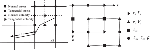
A fracture is a type of broken rock matrix. In porous media, fractures exhibit a complex geometric structure; that is, their shape is typically irregular, and they are at a certain angle with the finite difference grid. Muir et al. (1992) indicated that the cell grid can be considered an inclined medium, and the ratio of the two media is set based on the area of each medium in the grid cell and weighted according to the volume of each medium in the cell. In other words, for an element grid with an inclined fracture, the elastic constants of the element grid should be the average of the media in the upper and lower parts of the mesh. Subsequently, Coates and Schoenberg (1995) replaced the fracture and the elastic medium in the grid surrounding the fracture with equivalent anisotropy. They calculated the length, direction of the fracture and the local value of the compliance matrix of the fracture in each element grid and finally modelled the linear slip fracture. Figure 1(a) shows the basic elements of a fracture using a traditional grid. In the figure, Δ l $\Delta l$ represents the length of the fracture in the cell grid. The length of the fracture in each cell grid is different because of the irregular shape of the fracture. Δ S $\Delta S$ represents the area of the cell grid. This method does not consider the geometric structure of the fracture in the element grid, and the proportion of elastic parameters is described by L = Δ l / Δ S $L = \Delta l/\Delta S$ (Schoenberg & Muir, 1989). According to the method proposed by Hood (1991), a fracture is introduced into the rock group elements and inverted to obtain the compliance matrix of the equivalent medium. The compliance matrix of the fracture equivalent medium is obtained by adding it to the background medium (Coates & Schoenberg, 1995):
s = s b + s f = s b + Δ l Δ S 0 0 0 0 0 0 0 0 0 0 0 0 0 0 0 0 S N 0 0 0 0 0 0 0 S T 0 0 0 0 0 0 0 S T 0 0 0 0 0 0 0 0 0 0 0 0 0 0 0 0 , \begin{equation}{{\bf s}} = {{{\bf s}}_b} + {{{\bf s}}_f} = {{{\bf s}}_b} + \frac{{\Delta l}}{{\Delta S}}\left[ { \def\eqcellsep{&}\begin{array}{@{}*{7}{c}@{}} 0&0&0&0&0&0&0\\ 0&0&0&0&0&0&0\\ 0&0&{{S_N}}&0&0&0&0\\ 0&0&0&{{S_T}}&0&0&0\\ 0&0&0&0&{{S_T}}&0&0\\ 0&0&0&0&0&0&0\\ 0&0&0&0&0&0&0 \end{array} } \right],\end{equation} (2)
where s b ${{{\bf s}}_b}$ represents the compliance of the background medium and s f ${{{\bf s}}_f}$ represents the excess compliance, which is caused by fracture. However, Coates and Schoenberg (1995) use an isotropic background medium, while this study used a two-phase background medium. Therefore, the size of the compliance matrix differed from that of Coates and Schoenberg (1995). According to the method proposed by Hood (1991), the two-phase medium compliance matrix is 7 × 7 in size, while the isotropic medium compliance matrix is 6 × 6 in size. Assuming that the background medium is a two-phase medium, the background medium has a solid phase and a fluid phase. The interaction between the fluid and solid phases further complicates the elastic wave propagation in the two-phase media. The stiffness matrix in a two-phase medium with complex-shaped fractures is derived in the following section.
Details are in the caption following the image
(a) Fracture passing through the cell grid. Δ S $\Delta S$ represents the area of the cell grid, and Δ l $\Delta l$ represents the length of the fault in the cell grid. (b) Component distribution of elastic wave field in two-phase medium staggered grid.

Motion equation of two-phase fractured media

When a seismic wave propagates in a two-phase medium comprising a solid phase and a fluid phase, the interaction between both the phases should be considered. Biot (1956) was the first to propose the theory of elastic wave propagation in two-phase media. According to Biot's theory, the framework is composed of an elastic isotropic solid containing pore, and the pore space is filled with compressible fluid. The relative movement of solids and fluids can result in friction. Assuming an isotropic two-phase medium and its corresponding motion equation (Dai et al., 1995), and considering the relationship between the strain and stress of the solid and fluid phases, the stiffness matrix of a two-phase medium can be obtained by transforming the motion equation as follows:
c b = 2 N + A A A 0 0 0 Q A 2 N + A A 0 0 0 Q A A 2 N + A 0 0 0 Q 0 0 0 N 0 0 0 0 0 0 0 N 0 0 0 0 0 0 0 N 0 Q Q Q 0 0 0 R . \begin{equation}{{{\bf c}}_b} = \left[ { \def\eqcellsep{&}\begin{array}{@{}*{7}{c}@{}} {2N + A}&A&A&0&0&0&Q\\ A&{2N + A}&A&0&0&0&Q\\ A&A&{2N + A}&0&0&0&Q\\ 0&0&0&N&0&0&0\\ 0&0&0&0&N&0&0\\ 0&0&0&0&0&N&0\\ Q&Q&Q&0&0&0&R \end{array} } \right].\end{equation} (3)
Matrix s b ${{{\bf s}}_b}$ can be obtained by inverting matrix c b ${{{\bf c}}_b}$ . Equation (3) indicates that only four parameters such as A, N, Q and R are required for the stiffness matrix of two-phase isotropic media, where A andN are equivalent to λ and μ in a single-phase isotropic medium, respectively; Q = K ϕ R $Q = K\phi - R$ represents the coupling coefficient of the volume change between the solid and fluid phases, where K is the elastic parameter of the two-phase medium, for which the specific calculation refers to Geertsma and Smit (1961); and R = L ϕ 2 $R = L{\phi ^2}$ (where ϕ represents the porosity of the medium) is the elastic parameter that describes the pore fluid, which is a measure of the force that acts on the fluid when a specific fluid volume is forced to flow into the volume element of the two-phase medium; while maintaining a constant total volume constant. Please refer to Appendix B for the detailed calculation of A, N, Q and R. The stiffness matrix can be obtained by inverting the matrix of the equivalent medium c = s 1 = ( s b + s f ) 1 = c b ( I + s f c b ) 1 ${{\bf c}} = {{{\bf s}}^{ - 1}} = {( {{{{\bf s}}_b} + {{{\bf s}}_f}} )^{ - 1}} = {{{\bf c}}_b}{( {{{\bf I}} + {{{\bf s}}_f}{{{\bf c}}_b}} )^{ - 1}}$ (Coates & Schoenberg, 1995), where I is the identity matrix, and equations (2) and (3) are input into the stiffness matrix, the stiffness matrix of the two-phase isotropic medium with complex shape fractures can be expressed as follows:
c = 2 N + A 1 r 2 δ N A 1 r δ N A 1 δ N 0 0 0 Q A 1 r δ N 2 N + A 1 r 2 δ N A 1 δ N 0 0 0 Q A 1 δ N A 1 δ N 2 N + A 1 δ N 0 0 0 Q 0 0 0 N 1 δ T 0 0 0 0 0 0 0 N 1 δ T 0 0 0 0 0 0 0 N 0 Q Q Q 0 0 0 R , \begin{equation}{{\bf c}} = \left[ { \def\eqcellsep{&}\begin{array}{@{}*{7}{c}@{}} {\left( {2N + A} \right)\left( {1 - {r^2}{\delta _N}} \right)}&{A\left( {1 - r{\delta _N}} \right)}&{A\left( {1 - {\delta _N}} \right)}&0&0&0&Q\\ {A\left( {1 - r{\delta _N}} \right)}&{\left( {2N + A} \right)\left( {1 - {r^2}{\delta _N}} \right)}&{A\left( {1 - {\delta _N}} \right)}&0&0&0&Q\\ {A\left( {1 - {\delta _N}} \right)}&{A\left( {1 - {\delta _N}} \right)}&{\left( {2N + A} \right)\left( {1 - {\delta _N}} \right)}&0&0&0&Q\\ 0&0&0&{N\left( {1 - {\delta _T}} \right)}&0&0&0\\ 0&0&0&0&{N\left( {1 - {\delta _T}} \right)}&0&0\\ 0&0&0&0&0&N&0\\ Q&Q&Q&0&0&0&R \end{array} } \right],\end{equation} (4)
where r = A / ( A + 2 N ) $r = A/( {A + 2N} )$ , δ T = N S T / ( L + N S T ) ${\delta _T} = N{S_T}/( {L + N{S_T}} )$ , and δ N = ( A + 2 N ) S N / [ L + ( A + 2 N ) S N ] ${\delta _N} = ( {A + 2N} ){S_N}/[ {L + ( {A + 2N} ){S_N}} ]$ .
Moreover, Biot (1956) predicted that there are two types of P-waves in two-phase media: a fast P-wave (the first type of P-wave) and a slow P-wave (the second type of P-wave). Plona (1980) confirmed the validity of this theory. Based on this theory, the motion equation of a two-phase isotropic elastic wave can be expressed as follows (Dai et al., 1995):
v x t = D 2 + D 3 b v x V x D 3 τ x x x + τ x z z + D 2 ς x v z t = D 2 + D 3 b v z V z D 3 τ x z x + τ z z z + D 2 ς z V x t = D 1 + D 2 b v x V x + D 2 τ x x x + τ x z z D 1 ς x V z t = D 1 + D 2 b v z V z + D 2 τ x z x + τ z z z D 1 ς z τ x x t = c 11 v x x + c v z z + Q V x x + V z z τ z z t = c 13 v x x + c 33 v z z + Q V x x + V z z τ x z t = c 55 v x z + v z x ς t = Q v x x + Q v z z + R V x x + V z z , \begin{equation} \def\eqcellsep{&}\begin{array}{l} \frac{{\partial {v_x}}}{{\partial t}} = \left( {{D_2} + {D_3}} \right)b\left( {{v_x} - {V_x}} \right) - {D_3}\left( {\frac{{\partial {\tau _{xx}}}}{{\partial x}} + \frac{{\partial {\tau _{xz}}}}{{\partial z}}} \right) + {D_2}\frac{{\partial \varsigma }}{{\partial x}}\\ \frac{{\partial {v_z}}}{{\partial t}} = \left( {{D_2} + {D_3}} \right)b\left( {{v_z} - {V_z}} \right) - {D_3}\left( {\frac{{\partial {\tau _{xz}}}}{{\partial x}} + \frac{{\partial {\tau _{zz}}}}{{\partial z}}} \right) + {D_2}\frac{{\partial \varsigma }}{{\partial z}}\\ \frac{{\partial {V_x}}}{{\partial t}} = - \left( {{D_1} + {D_2}} \right)b\left( {{v_x} - {V_x}} \right) + {D_2}\left( {\frac{{\partial {\tau _{xx}}}}{{\partial x}} + \frac{{\partial {\tau _{xz}}}}{{\partial z}}} \right) - {D_1}\frac{{\partial \varsigma }}{{\partial x}}\\ \frac{{\partial {V_z}}}{{\partial t}} = - \left( {{D_1} + {D_2}} \right)b\left( {{v_z} - {V_z}} \right) + {D_2}\left( {\frac{{\partial {\tau _{xz}}}}{{\partial x}} + \frac{{\partial {\tau _{zz}}}}{{\partial z}}} \right) - {D_1}\frac{{\partial \varsigma }}{{\partial z}}\\ \frac{{\partial {\tau _{xx}}}}{{\partial t}} = {c_{11}}\frac{{\partial {v_x}}}{{\partial x}} + c\frac{{\partial {v_z}}}{{\partial z}} + Q\left( {\frac{{\partial {V_x}}}{{\partial x}} + \frac{{\partial {V_z}}}{{\partial z}}} \right)\\ \frac{{\partial {\tau _{zz}}}}{{\partial t}} = {c_{13}}\frac{{\partial {v_x}}}{{\partial x}} + {c_{33}}\frac{{\partial {v_z}}}{{\partial z}} + Q\left( {\frac{{\partial {V_x}}}{{\partial x}} + \frac{{\partial {V_z}}}{{\partial z}}} \right)\\ \frac{{\partial {\tau _{xz}}}}{{\partial t}} = {c_{55}}\left( {\frac{{\partial {v_x}}}{{\partial z}} + \frac{{\partial {v_z}}}{{\partial x}}} \right)\\ \frac{{\partial \varsigma }}{{\partial t}} = Q\frac{{\partial {v_x}}}{{\partial x}} + Q\frac{{\partial {v_z}}}{{\partial z}} + R\left( {\frac{{\partial {V_x}}}{{\partial x}} + \frac{{\partial {V_z}}}{{\partial z}}} \right), \end{array} \end{equation} (5)
where t represents the time, v and V represent the particle velocities of the solid-phase medium and fluid-phase medium, respectively; τ and ς represent the forces acting on the solid and fluid phases, respectively; subscripts ‘x’(xz) and ‘z’(xx, zz) represent the normal and tangential components, respectively; Q represents the coupling coefficient of the volume change between the solid and fluid phases; D 1 = ρ 11 / ( ρ 12 2 ρ 11 ρ 22 ) ${D_1} = {\rho _{11}}/( {\rho _{12}^2 - {\rho _{11}}{\rho _{22}}} )$ , D 2 = ρ 12 / ( ρ 12 2 ρ 11 ρ 22 ) ${D_2} = {\rho _{12}}/( {\rho _{12}^2 - {\rho _{11}}{\rho _{22}}} )$ and D 3 = ρ 22 / ( ρ 12 2 ρ 11 ρ 22 ) ${D_3} = {\rho _{22}}/( {\rho _{12}^2 - {\rho _{11}}{\rho _{22}}} )$ ; ρ 11 = ρ s ( 1 ϕ ) + ϕ ρ f ( κ 1 ) ${\rho _{11}} = {\rho _s}(1 - \phi ) + \phi {\rho _f}(\kappa - 1)$ and ρ 22 = κ ϕ ρ f ${\rho _{22}} = \kappa \phi {\rho _f}$ represent the effective densities of the solid and fluid phases in a unit volume of the medium, respectively; ρ 12 = ϕ ρ f ( 1 κ ) ${\rho _{12}} = \phi {\rho _f}(1 - \kappa )$ is the coupled density between the solid and fluid in the two-phase medium; ρ s ${\rho _s}$ indicates the density of the solid skeleton; ρ f ${\rho _f}$ represents the density of the pore fluid; and κ = 1 χ ( 1 1 / ϕ ) $\kappa = 1 - \chi (1 - 1/\phi )$ represents the tortuosity parameter, which is related to the porosity and pore shape. When the pores are spherical, χ = 0.5 $\chi = 0.5$ . Please refer to Berryman (1980) for a detailed description. b is the dissipation coefficient ( kg · m 3 s 1 ${\rm{kg}} \cdot {{\rm{m}}^{ - 3}}{{\rm{s}}^{ - 1}}$ ), which is expressed as the amplitude attenuation value of the solid–fluid relative motions over time. Although equation (5) has the same expression as equation (5) proposed by Dai et al. (1995), the meanings of the stiffness matrix differ. The stiffness matrix of equation (5) is equation (4), which contains the fracture compliance parameters, while the equation proposed by Dai et al. (1995) lacks these parameters. Therefore, equation (5) can be used to simulate seismic wave propagation in a two-phase complex-shaped fractured medium.

Finite difference scheme

In this study, the standard staggered-grid and the first-order velocity stress two-dimensional algorithm were used to simulate seismic waves in a two-phase fractured medium (Dai et al., 1995). The staggered-grid finite-difference method divides the model into multiple grids according to a specific grid spacing and defines the variables to be calculated at each grid node, in which the stress and velocity components are defined at different positions (Virieux, 1986). Figure 1(b) shows the locations of the stress and velocity components of the two-phase medium in a standard staggered grid.

According to the staggered grid principle, the derivative of a variable is calculated halfway between the grid points of the corresponding variable. Therefore, the finite-difference method requires a large number of calculations. In order to balance the calculation accuracy and the number of calculations, the second-order time and the fourth-order space are generally used to discretize the finite-difference formula (Moczo et al., 2000). Finally, using the normal velocity of the particles in the fluid-phase medium V z ${V_z}$ and the normal stress of the particles in the solid-phase medium τ x x ${\tau _{xx}}$ in equation (5) as examples, their discrete forms in the second-order time and the fourth-order space are given by
V x i + 1 / 2 , j t = V x i + 1 / 2 , j t 1 Δ t D 1 + D 2 b 11 v x i + 1 / 2 , j t 1 V x i + 1 / 2 , j t 1 + Δ t Δ x D 2 C 1 τ x x i + 1 , j t 1 / 2 τ x x i 1 , j t 1 / 2 + C 2 τ x x i + 2 , j t 1 / 2 τ x x i 2 , j t 1 / 2 + Δ t Δ z D 2 { C 1 [ ( τ x z ) i + 1 / 2 , j + 1 / 2 t 1 / 2 ( τ x x ) i + 1 / 2 , j 1 / 2 t 1 / 2 ] + C 2 ( τ x z ) i + 1 / 2 , j + 3 / 2 t 1 / 2 ( τ x x ) i + 1 / 2 , j 3 / 2 t 1 / 2 } Δ t Δ x D 1 { C 1 [ ς i + 1 , j t 1 / 2 ς i 1 , j t 1 / 2 ] + C 2 [ ς i + 2 , j t 1 / 2 ς i 2 , j t 1 / 2 ] \begin{eqnarray}&& \left( {{V_x}} \right)_{i + 1/2,j}^t = \left( {{V_x}} \right)_{i + 1/2,j}^{t - 1} - \Delta t\left( {{D_1} + {D_2}} \right){b_{11}}\left[ {\left( {{v_x}} \right)_{i + 1/2,j}^{t - 1} - \left( {{V_x}} \right)_{i + 1/2,j}^{t - 1}} \right]\nonumber\\ &&+\; \frac{{\Delta t}} {{\Delta x}} {D_2}\left\{ {{C_1}\left[ {\left( {{\tau _{xx}}} \right)_{i + 1,j}^{t - 1/2} - \left( {{\tau _{xx}}} \right)_{i - 1,j}^{t - 1/2}} \right] + {C_2}\left[ {\left( {{\tau _{xx}}} \right)_{i + 2,j}^{t - 1/2} - \left( {{\tau _{xx}}} \right)_{i - 2,j}^{t - 1/2}} \right]} \right\}\nonumber\\ && +\; \frac{{\Delta t}} {{\Delta z}} {D_2}\ {\{C_1}[ {( {{\tau _{xz}}} )_{i + 1/2,j + 1/2}^{t - 1/2} - ( {{\tau _{xx}}} )_{i + 1/2,j - 1/2}^{t - 1/2}} ]\nonumber\\ &&+\; {C_2} \left[ {( {{\tau _{xz}}} )_{i + 1/2,j + 3/2}^{t - 1/2} - ( {{\tau _{xx}}} )_{i + 1/2,j - 3/2}^{t - 1/2}} \right] \}\nonumber\\ && -\; \frac{{\Delta t}}{{\Delta x}}{D_1}\{ {{C_1}[ {\varsigma _{i + 1,j}^{t - 1/2} - \varsigma _{i - 1,j}^{t - 1/2}} ] + {C_2}[ {\varsigma _{i + 2,j}^{t - 1/2} - \varsigma _{i - 2,j}^{t - 1/2}} ]} \, \end{eqnarray} (6)
τ x x i , j t + 1 / 2 = τ x x i , j t + 1 / 2 + Δ t Δ x 2 N + A 1 r 2 δ N C 1 v x i + 1 / 2 , j t v x i 1 / 2 , j t + C 2 v x i + 3 / 2 , j t v x i 3 / 2 , j t + Δ t Δ z A 1 δ N C 1 v z i , j + 1 / 2 t v z i , j 1 / 2 t + C 2 v z i , j + 3 / 2 t v z i , j 3 / 2 t + Δ t Δ x Q 1 C 1 V x i + 1 / 2 , j t V x i 1 / 2 , j t + C 2 V x i + 3 / 2 , j t V x i 3 / 2 , j t + Δ t Δ z Q 1 C 1 V z i , j + 1 / 2 t V z i , j 1 / 2 t + C 2 V z i , j + 3 / 2 t V z i , j 3 / 2 t , \begin{equation} \def\eqcellsep{&}\begin{array}{l} \left( {{\tau _{xx}}} \right)_{i,j}^{t + 1/2} = \left( {{\tau _{xx}}} \right)_{i,j}^{t + 1/2}\\[6pt] + \frac{{\Delta t}}{{\Delta x}}\left( {2N + A} \right)\left( {1 - {r^2}{\delta _N}} \right)\\[6pt] \left\{ {{C_1}\left[ {\left( {{v_x}} \right)_{i + 1/2,j}^t - \left( {{v_x}} \right)_{i - 1/2,j}^t} \right] + {C_2}\left[ {\left( {{v_x}} \right)_{i + 3/2,j}^t - \left( {{v_x}} \right)_{i - 3/2,j}^t} \right]} \right\}\\[6pt] + \frac{{\Delta t}}{{\Delta z}}A\left( {1 - {\delta _N}} \right)\left\{ {{C_1}\left[ {\left( {{v_z}} \right)_{i,j + 1/2}^t - \left( {{v_z}} \right)_{i,j - 1/2}^t} \right] + {C_2}\left[ {\left( {{v_z}} \right)_{i,j + 3/2}^t - \left( {{v_z}} \right)_{i,j - 3/2}^t} \right]} \right\}\\[6pt] + \frac{{\Delta t}}{{\Delta x}}{Q_1}\left\{ {{C_1}\left[ {\left( {{V_x}} \right)_{i + 1/2,j}^t - \left( {{V_x}} \right)_{i - 1/2,j}^t} \right] + {C_2}\left[ {\left( {{V_x}} \right)_{i + 3/2,j}^t - \left( {{V_x}} \right)_{i - 3/2,j}^t} \right]} \right\}\\[6pt] + \frac{{\Delta t}}{{\Delta z}}{Q_1}\left\{ {{C_1}\left[ {\left( {{V_z}} \right)_{i,j + 1/2}^t - \left( {{V_z}} \right)_{i,j - 1/2}^t} \right] + {C_2}\left[ {\left( {{V_z}} \right)_{i,j + 3/2}^t - \left( {{V_z}} \right)_{i,j - 3/2}^t} \right]} \right\}, \end{array} \end{equation} (7)

where C1 and C2 are finite-differential coefficients and different difference accuracies correspond to different finite differential coefficients. It was obtained according to Taylor expansion and first proposed by Dablain (1986). Fornberg (1998) introduced the calculation of spatial difference coefficient and discussed it in detail. When the difference accuracy is of the second order, C 1 = 1 ${C_1} = 1$ , C 2 = 0 ${C_2} = 0$ . When the difference accuracy is of the fourth order, C 1 = 1.171 ${C_1} = 1.171$ , C 2 = 0.041 ${C_2} = - 0.041$ . The difference schemes of the other v x ${v_x}$ , v z ${v_z}$ , V z ${V_z}$ , τ z z ${\tau _{zz}}$ and ς parameters can be obtained in the same way.

The long-term stability analysis reflects the ability of finite-difference scheme to control error transmission in the calculation process. For a long time period, when the numerical value is stable and does not change with time, then the difference scheme is said to be stable. The long-term stability of the velocity wave field can be calculated as E ( t ) = 1 n i j v i , j , t 2 ( t ) $E( t ) = \frac{1}{n}\sum_i {\sum_j {v_{i,j,t}^2( t )} } $ , where n is the number of grids in the test model, i , j $i,j$ represent the position of the grid point, and v is the velocity wave field. E is the average grid energy, which represents the average value of the square of the velocity values at all grid points for each time. When the results (grid energy) do not change, the numerical simulation scheme is regarded as having long-term stability. For details, please refer to Cheng et al. (2017).

Reflection and transmission coefficients of fracture interface

The energy distribution law of seismic waves on the fracture interface is the solution of the elastic wave equation plus interface condition, which represents the basic theory behind AVO technology. Presently, the forward and inversion modelling of AVO are based on the Zoeppritz equation of single-phase media. However, the reservoir is a two-phase medium with a solid and a fluid phase. Studying the reflection and transmission coefficients of the linear slip fracture boundary in porous media can reduce the number of multiple solutions in the AVO method while predicting reservoir parameters. The equation of reflection and transmission coefficients at the fracture interface in a two-phase medium at any incident angle is established.

In the horizontal fracture in a two-phase medium, six types of waves are typically generated when a P-wave, P1, is incident from the two-phase background medium to the horizontal fracture interface at an angle, α1. The six types of waves include incident P-wave (P1), reflected fast P-wave (P11), reflected slow P-wave (P12), reflected S-wave (S1), transmitted fast P-wave (P21), transmitted slow P-wave (P22) and transmitted S-wave (S2). The plane wave expressions for the P-wave potentials of the incident wave can be expressed as follows:
φ 1 s = A p 1 exp i ω t l 1 x sin α 1 + z cos α 1 φ 1 f = B p 1 exp i ω t l 1 x sin α 1 + z cos α 1 , \begin{equation} \def\eqcellsep{&}\begin{array}{l} \varphi _1^s = {A_{{p_1}}}\exp i\left[ {\omega t - {l_1}\left( {x\sin {\alpha _1} + z\cos {\alpha _1}} \right)} \right]\\ \varphi _1^f = {B_{{p_1}}}\exp i\left[ {\omega t - {l_1}\left( {x\sin {\alpha _1} + z\cos {\alpha _1}} \right)} \right], \end{array} \end{equation} (8)
where φ 1 s $\varphi _1^s$ represents the solid potential of the incident wave, φ 1 f $\varphi _1^f$ represents the fluid potential of the incident wave. A p 1 ${A_{{p_1}}}$ represents the amplitude of the solid potential of the incident wave p1, B p 1 ${B_{{p_1}}}$ represents the amplitude of fluid potential of the incident wavep1, ω represents the circular frequency, l1 represents the circular wave number, and α1 represents the incident angle. Similar expressions can be written for the other waves (see Appendix A).
Combining Lovera (1987) and the linear slip theory, we propose the following boundary conditions of the horizontal fracture interface in a two-phase medium: discontinuous normal displacement of solid [ u z ] + = [ u z ] + S N τ z z ${[ {{u_z}} ]^ + } = {[ {{u_z}} ]^ - } + {S_N}{\tau _{zz}}$ , discontinuous tangential displacement of solid [ u x ] + = [ u x ] + S T τ x z ${[ {{u_x}} ]^ + } = {[ {{u_x}} ]^ - } + {S_T}{\tau _{xz}}$ , continuous total normal stress [ τ z z + ς ] + = [ τ z z + ς ] ${[ {{\tau _{zz}} + \varsigma } ]^ + } = {[ {{\tau _{zz}} + \varsigma } ]^ - }$ , continuous tangential stress of solid [ τ z x ] + = [ τ z x ] ${[ {{\tau _{zx}}} ]^ + } = {[ {{\tau _{zx}}} ]^ - }$ , continuous normal flow of fluid [ ϕ ( u z U z ) ] + = [ ϕ ( u z U z ) ] ${[ {\phi ( {{u_z} - {U_z}} )} ]^ + } = {[ {\phi ( {{u_z} - {U_z}} )} ]^ - }$ , and continuous pressure of fluid [ 1 ϕ ( Q e + R ε ) ] + = [ 1 ϕ ( Q e + R ε ) ] ${[ {\frac{1}{\phi }( {Qe + R\varepsilon } )} ]^ + } = {[ {\frac{1}{\phi }( {Qe + R\varepsilon } )} ]^ - }$ , where u x ${u_x}$ and u z ${u_z}$ represent the tangential and normal displacements of the solid, respectively; U x ${U_x}$ and U z ${U_z}$ represent the tangential and normal displacements of the fluid, respectively; ς = Q e + R ε $\varsigma = Qe + R\varepsilon $ represents the forces acting on the fluid phase; e = e x x + e z z $e = {e_{xx}} + {e_{zz}}$ represents the volume strain of the solid; and ε = U x x + U z z $\varepsilon = \frac{{\partial {U_x}}}{{\partial x}} + \frac{{\partial {U_z}}}{{\partial z}}$ represents the volume strain of the fluid. By solving the boundary conditions (see Appendix A for the specific process), the equations of the reflection and transmission coefficients of the horizontal fracture interface in a two-phase medium can be obtained as follows:
cos α 11 cos α 12 sin β 1 cos α 21 i S N λ l 21 i S N 2 μ cos 2 α 21 sin α 11 sin α 12 cos β 1 sin α 21 i S T μ l 21 sin 2 α 21 l 11 λ + 2 μ cos 2 α 11 + Q + R + Q B p 11 A p 11 l 12 λ + 2 μ cos 2 α 12 + Q + R + Q B p 12 A p 12 μ l s 1 sin 2 β 1 l 21 λ + 2 μ cos 2 α 21 + Q + R + Q B p 21 A p 21 l 11 sin 2 α 11 l 12 sin 2 α 12 l s 1 cos 2 β 1 l 21 sin 2 α 21 1 B p 11 A p 11 cos α 11 1 B p 12 A p 12 cos α 12 1 + ρ 12 ρ 22 sin β 1 1 B p 21 A p 21 cos α 21 l 11 Q + R B p 11 A p 11 l 11 Q + R B p 11 A p 11 0 l 21 Q + R B p 21 A p 21 cos α 22 i S N λ l 22 sin β 2 + i S N μ l s 2 sin 2 β 2 sin α 22 i S T μ l 22 sin 2 α 22 cos β 2 i S T μ l s 2 cos 2 β 2 l 22 λ + 2 μ l 22 cos 2 α 22 + Q + R + Q B p 22 A p 22 μ l s 2 sin 2 β 2 l 22 sin 2 α 22 l s 2 cos 2 β 2 1 B p 22 A p 22 cos α 22 1 + ρ 12 ρ 22 sin β 2 l 22 Q + R B p 22 A p 22 0 R p 11 R p 12 R s 1 T p 21 T p 22 T s 2 = cos α 1 sin α 1 l 1 λ + 2 μ cos 2 α 1 + Q + R + Q B p 1 A p 1 l 1 sin 2 α 1 1 B p 1 A p 1 cos α 1 l 1 Q + R B p 1 A p 1 , \begin{equation} \def\eqcellsep{&}\begin{array}{l} \left[ { \def\eqcellsep{&}\begin{array}{@{}*{4}{c}@{}} {\cos {\alpha _{11}}}&{\cos {\alpha _{12}}}&{ - \sin {\beta _1}}& \def\eqcellsep{&}\begin{array}{l} \cos {\alpha _{21}} - i{S_N}\lambda {l_{21}}\\ - i{S_N}2\mu {\cos ^2}{\alpha _{21}} \end{array} \\ {\sin {\alpha _{11}}}&{\sin {\alpha _{12}}}&{\cos {\beta _1}}&{ - \left( {\sin {\alpha _{21}} - i{S_T}\mu {l_{21}}\sin 2{\alpha _{21}}} \right)}\\ {{l_{11}}\left( \def\eqcellsep{&}\begin{array}{l} \lambda + 2\mu {\cos ^2}{\alpha _{11}}\\ + Q + \left( {R + Q} \right)\frac{{{B_{p11}}}}{{{A_{p11}}}} \end{array} \right)}&{{l_{12}}\left( \def\eqcellsep{&}\begin{array}{l} \lambda + 2\mu {\cos ^2}{\alpha _{12}}\\ + Q + \left( {R + Q} \right)\frac{{{B_{{p_{12}}}}}}{{{A_{{p_{12}}}}}} \end{array} \right)}&{ - \mu {l_{s1}}\sin 2{\beta _1}}&{ - {l_{21}}\left( \def\eqcellsep{&}\begin{array}{l} \lambda + 2\mu {\cos ^2}{\alpha _{21}}\\ + Q + \left( {R + Q} \right)\frac{{{B_{{p_{21}}}}}}{{{A_{{p_{21}}}}}} \end{array} \right)}\\ {{l_{11}}\sin 2{\alpha _{11}}}&{{l_{12}}\sin 2{\alpha _{12}}}&{{l_{s1}}\cos 2{\beta _1}}&{{l_{21}}\sin 2{\alpha _{21}}}\\ {\left( {1 - \frac{{{B_{{p_{11}}}}}}{{{A_{p11}}}}} \right)\cos {\alpha _{11}}}&{\left( {1 - \frac{{{B_{{p_{12}}}}}}{{{A_{{p_{12}}}}}}} \right)\cos {\alpha _{12}}}&{ - \left( {1 + \frac{{{\rho _{12}}}}{{{\rho _{22}}}}} \right)\sin {\beta _1}}&{\left( {1 - \frac{{{B_{{p_{21}}}}}}{{{A_{{p_{21}}}}}}} \right)\cos {\alpha _{21}}}\\ {{l_{11}}\left( {Q + R\frac{{{B_{{p_{11}}}}}}{{{A_{{p_{11}}}}}}} \right)}&{{l_{11}}\left( {Q + R\frac{{{B_{{p_{11}}}}}}{{{A_{{p_{11}}}}}}} \right)}&0&{ - {l_{21}}\left( {Q + R\frac{{{B_{{p_{21}}}}}}{{{A_{{p_{21}}}}}}} \right)} \end{array} } \right.\\ \\ \left. { \def\eqcellsep{&}\begin{array}{@{}*{2}{c}@{}} {\cos {\alpha _{22}} - i{S_N}\lambda {l_{22}}}&{ - \left( {\sin {\beta _2} + i{S_N}\mu {l_{s2}}\sin 2{\beta _2}} \right)}\\ { - \left( {\sin {\alpha _{22}} - i{S_T}\mu {l_{22}}\sin 2{\alpha _{22}}} \right)}&{ - \left( {\cos {\beta _2} - i{S_T}\mu {l_{s2}}\cos 2{\beta _2}} \right)}\\ { - {l_{22}}\left( \def\eqcellsep{&}\begin{array}{l} \lambda + 2\mu {l_{22}}{\cos ^2}{\alpha _{22}}\\ + Q + \left( {R + Q} \right)\frac{{{B_{{p_{22}}}}}}{{{A_{{p_{22}}}}}} \end{array} \right)}&{\mu {l_{s2}}\sin 2{\beta _2}}\\ {{l_{22}}\sin 2{\alpha _{22}}}&{{l_{s2}}\cos 2{\beta _2}}\\ {\left( {1 - \frac{{{B_{{p_{22}}}}}}{{{A_{{p_{22}}}}}}} \right)\cos {\alpha _{22}}}&{ - \left( {1 + \frac{{{\rho _{12}}}}{{{\rho _{22}}}}} \right)\sin {\beta _2}}\\ { - {l_{22}}\left( {Q + R\frac{{{B_{{p_{22}}}}}}{{{A_{{p_{22}}}}}}} \right)}&0 \end{array} } \right]\left[ { \def\eqcellsep{&}\begin{array}{@{}*{1}{c}@{}} {{R_{{p_{11}}}}}\\ {{R_{{p_{12}}}}}\\ {{R_{{s_1}}}}\\ {{T_{{p_{21}}}}}\\ {{T_{{p_{22}}}}}\\ {{T_{{s_2}}}} \end{array} } \right] = \left[ { \def\eqcellsep{&}\begin{array}{@{}*{1}{c}@{}} {\cos {\alpha _1}}\\ { - \sin {\alpha _1}}\\ { - {l_1}\left( \def\eqcellsep{&}\begin{array}{l} \lambda + 2\mu {\cos ^2}{\alpha _1}\\ + Q + \left( {R + Q} \right)\frac{{{B_{p1}}}}{{{A_{p1}}}} \end{array} \right)}\\ {{l_1}\sin 2{\alpha _1}}\\ {\left( {1 - \frac{{{B_{p1}}}}{{{A_{p1}}}}} \right)\cos {\alpha _1}}\\ { - {l_1}\left( {Q + R\frac{{{B_{p1}}}}{{{A_{p1}}}}} \right)} \end{array} } \right], \end{array} \end{equation} (9)
where R p 11 ${R_{{p_{11}}}}$ is the reflection coefficient of the fast P-wave, R p 12 ${R_{{p_{12}}}}$ is the reflection coefficient of the slow P-wave, R s 1 ${R_{{s_1}}}$ is the reflection coefficient of the S-wave, T p 21 ${T_{{p_{21}}}}$ is the transmission coefficient of the fast P-wave, T p 22 ${T_{{p_{22}}}}$ is the transmission coefficient of the slow P-wave, and T s 2 ${T_{{s_2}}}$ is the transmission coefficient of the S-wave. These coefficients are defined in Appendix A.
According to Wang et. al. (2020), the reflection coefficient can be described as
R r = R r exp i θ r , \begin{equation}{R_r} = \left| {{R_r}} \right|\exp \left( {i{\theta _r}} \right)\!,\end{equation} (10)
where the subscript r represents the six waves mentioned in equation (9), R r ${R_r}$ is the reflection coefficient and | R r | $| {{R_r}} |$ is the reflection amplitude, θ represents the phase angle.

Numerical simulation and discussion

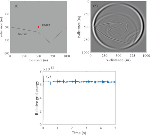
We first consider two-phase isotropic elastic media with the same grid spacing in the x and z directions. The first model described in this section represents an irregular fracture interface inserted into an isotropic homogeneous background. The relevant parameters of the model are P-wave velocity v p = 2800 m / s ${v_p} = 2800\ {\rm{m}}/{\rm{s}}$ and S-wave velocity v s = 1400 m / s ${v_s} = 1400\ {\rm{m}}/{\rm{s}}$ . The effective density of the model medium was ρ = 2670 kg / m 3 $\rho = 2670\ {\rm{kg}}/{{\rm{m}}^3}$ . The porosity of the model was ϕ = 0.12 $\phi = 0.12$ . The velocity of the model flow phase was v f = 1500 m / s ${v_f} = 1500\ {\rm{m}}/{\rm{s}}$ , and its effective density was ρ f = 1200 kg / m 3 ${\rho _f} = 1200\ {\rm{kg}}/{{\rm{m}}^3}$ . The values of the other parameters can be obtained from these six parameters. Detailed descriptions of the calculations can be found in Appendix B. The dissipation coefficients of the flow relative to the solid phase is b = 0.5 kg / m 3 $b = 0.5\ {\rm{kg}}/{{\rm{m}}^3}$ . The model size is 1000 × 1000 m $1000 \times 1000\ {\rm{m}}$ , the space grid parameter is Δ x = Δ z = 2 m $\Delta x = \Delta z = 2\ {\rm{m}}$ , and the time step is Δ t = 0.0001 s $\Delta t = 0.0001\ {\rm{s}}$ . Figure 2(a) shows that in the model, the fracture is irregular in shape. The seismic source was buried in the horizontal centre of the model, and the fracture parameters were normal compliance S N = 5.27 × 10 10 m / Pa ${S_N} = 5.27 \times {10^{10}}{\rm{m}}/{\rm{Pa}}$ and tangential compliance S T = 6.32 × 10 10 m / Pa ${S_T} = 6.32 \times {10^{10}}{\rm{m}}/{\rm{Pa}}$ . The model uses the Ricker wavelet with a dominant frequency of f = 35 Hz $f = 35\ {\rm{Hz}}$ as the source energy. The long-term stability of the new scheme was tested by running a simulation with a time of 5 s. Maintaining the parameters as constant, a pure reflection boundary was used to estimate the energy in the simulation. Figure 2(b) and (c) shows the v x ${v_x}$ wave field and long-term stability results, respectively. The results indicate that the proposed scheme is stable for long-term wave propagation.
Details are in the caption following the image
(a) The two-phase fractured medium, (b) its v x ${v_x}$ wave field snapshot and (c) long-term stability.

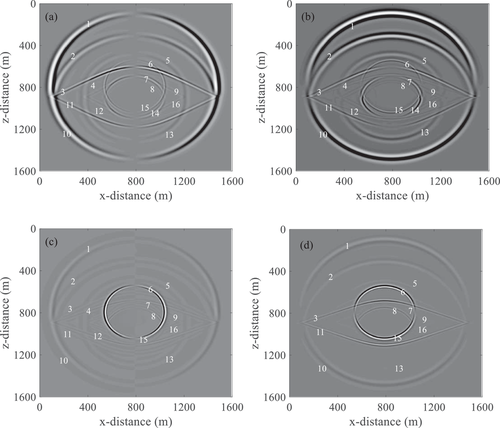
To analyse the seismic wave caused by the linear slip fracture interface, we used a single horizontal fracture and expanded the model size to 1600 × 1600 m. The seismic source was located at the centre of the model, the horizontal fracture was located 100 m below the seismic source. The remaining parameters remained unchanged. Figure 3 shows a snapshot of the wave field at 0.24 s as well as the seismic wave propagation of the model. Figure 3(a) and (b) represents the x and z components of the solid phase, respectively. Figure 3(c) and (d) represents the x and z components of the fluid phase, respectively. When the P-wave source is excited, both fast P-waves (the first type of wave) and slow P-waves (the second type of wave) are observed in the two-phase isotropic medium. Comparison of the P- and S-waves in Figure 3(a–d) shows that the velocities of the wave in the solid and fluid phases are the same. A comparison of Figure 3(a) and (c) indicates that the phases of the fast P-waves in the solid and flow phases are the same, whereas opposing phases were observed for the slow P-waves in the solid and flow phases, which is caused by the different vibrations of the fluid particles and the solid skeleton particles. All these are consistent with Biot's conclusion. Figure 3(c) and (d) show that the energy of the slow P-wave is much greater than that of the fast P-wave, such that a slow P-wave is easier to observe in the flow phase, which indicates that fast P-waves mainly propagate in the solid skeleton, while slow P-waves mainly propagate in the fluid. However, slow P-waves have a low velocity and strong attenuation and dispersion, such that it is difficult to observe in the actual seismic wave field; nevertheless, it cannot be ignored.
Details are in the caption following the image
Snapshots of the wave field of the two-phase isotropic fractured medium: (a) solid phase x component, (b) solid phase z component, (c) fluid phase x component and (d) fluid phase z component. Numbers 1−16 represent (1) fast P-wave, (2) reflected fast P-wave from fast P-wave, (3) reflected S-wave converted from a fast P-wave, (4) reflected slow P-wave converted from a fast P-wave, (5) reflected fast P-wave converted from a slow P-wave, (6) slow P-wave, (7) reflected S-wave converted from a slow P-wave, (8) slow P-wave converted from a slow P-wave, (9) refracted wave, (10) transmitted fast P-wave converted from a fast P-wave, (11) transmitted S-wave converted from a fast P-wave, (12) transmitted slow P-wave converted from a fast P-wave, (13) transmitted fast P-wave converted from a slow P-wave, (14) transmitted S-wave converted from a slow P-wave, (15) transmitted slow P-wave converted from a slow P-wave and (16) refracted wave.

At the linear slip fracture interface of the two-phase medium, the incident, reflected and transmitted waves of the two-phase isotropic fractured medium are constrained by the boundary conditions. Since the displacement is linearly proportional to the corresponding stress, the discontinuous particle displacement will cause the wave field to contain fast P-waves (1) (Number (1) in Fig. 3), and the reflected and transmitted waves of the fast P-wave include the fast P-wave converted S-wave (3) (11), and fast P-wave converted slow P-wave (4) (12). Considering the slow P-wave (6), the reflected and transmitted waves of the slow P-wave include the slow P-wave converted to fast P-wave (5) (13), slow P-wave converted to slow P-wave (8) (15), and slow P-wave converted to shear wave (7) (14). In summary, elastic waves will produce three kinds of waves on the interface of a two-phase fracture, namely fast P-waves, slow P-waves and converted S-waves. Fast P-waves and slow P-waves will transform each other when they encounter the interface and produce transmission or reflection. This is consistent with the waveform generated by the interface of two-phase media. This proves the Backus hypothesis, which regards the fracture as a thin layer with the thickness approaching zero. In this model, the fracture can be regarded as a two-phase interface with zero thickness. In addition, because the seismic source is close to the fracture interface and reaches a critical angle, two head waves (9) (16) caused by slow P-waves (6) can also be observed, which connect the reflected fast P-wave (5) and the reflected S-wave (7), the transmitted fast P-wave (13) and the transmitted S-wave (14), respectively. Owing to the strong attenuation of the slow P-wave (6), the reflected and transmitted slow P-wave (2) (10) caused by the fast P-wave (1) is very weak; hence, it is barely observed in the vertical component of the flow phase (Fig. 3d). The reflected and transmitted slow P-waves (8) (15) caused by slow P-waves (6) can be observed. By comparing Figure 3(a–d), under the same conditions, the solid phase S-wave is obvious, while the flow phase S-wave is weak. It is difficult to observe S-wave components in the flow phase; however, this does not mean that no S-waves are present in the current phase. When the fluid is an ideal non-viscoelastic fluid, the S-wave cannot propagate through the layer. However, the fluid in a two-phase medium exists in pores, and S-waves will be able to propagate. These waves should not be ignored, even if they are very small.

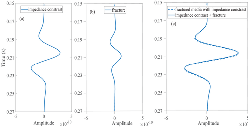
To better analyse the wave field characteristics of two-phase fractured media, we designed a model wherein both the upper and lower media were two-phase media, and the fracture and impedance interfaces coincided. According to Schoenberg and Muir (1989), the compliance matrix of the fracture is added to the compliance matrix of the background medium to yield the compliance matrix of the fracture equivalent medium. In other words, the fractured medium is the linear sum of the fractured and the background medium, that is, in a fractured medium with an impedance contrast (the impedance contrast and fracture interfaces are located on the same grid boundary), the amplitude of the reflected wave caused by the interface is equal to the sum of the amplitudes of the reflected waves attributed to the fracture and to the background impedance. Figure 4 illustrates this relationship: Figure 4(a) shows the amplitude of the fast P-wave in a background medium with impedance contrast, Figure 4(b) shows the amplitude of the fast P-wave caused by a fracture interface in a uniform background medium, and Figure 4(c) shows the sum of both as well as the amplitude of the fast P-wave in a fractured medium with impedance contrast. As the synthetic reflection waveform is basically coincident with the waveform simulated by the new scheme, the fast P-wave reflection can be divided into a reflection caused by the fracture and a reflection caused by the impedance interface, which confirms the accuracy of Schoenberg and Muir's views. Therefore, in an impedance medium with fractures, the response caused by the fracture can be subtracted from the seismic data and the response caused by the impedance can be better obtained.
Details are in the caption following the image
Reflected fast P-wave converted from a fast P-wave. (a) Reflected fast P-wave of the background impedance, (b) reflected fast P-wave caused by a fracture, (c) sum of (a) and (b) (solid line) and reflected fast P-wave of a fractured medium with an impedance contrast (dashed line).

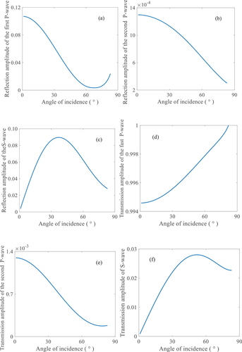
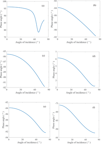
To study the effect of the fracture interface on the energy distribution of seismic waves in two-phase media, a model of two-phase isotropic background media with a single horizontal fracture was designed. The relevant parameters of the solid-phase component of the model are P-wave velocity v p = 2690 m / s ${v_p} = 2690\ {\rm{m}}/{\rm{s}}$ and S-wave velocity v s = 1727 m / s ${v_s} = 1727\ {\rm{m}}/{\rm{s}}$ . The effective density of the model medium is ρ = 2670 kg / m 3 $\rho = 2670\ {\rm{kg}}/{{\rm{m}}^3}$ . The porosity of the model is 0.12. The velocity of the model flow phase is v f = 1500 m / s ${v_f} = 1500\ {\rm{m}}/{\rm{s}}$ , and the effective density of the flow phase is ρ f = 1000 kg / m 3 ${\rho _f} = 1000\ {\rm{kg}}/{{\rm{m}}^3}$ . The fracture can be described by normal compliance and tangential compliance. Figure 5 shows the the amplitude spectrum (the root of the sum of the squares of the real and imaginary parts) of the reflection and transmission of the fracture interface at different incident angles. Figure 6 depicts the phase change at different incident angles. In two-phase fractured media, when the wave propagates to the fracture interface, the wave-induced flow causes the fluid to pass through it, which leads to the attenuation of propagation energy. The reflection amplitude of the fast P-waves initially decreases and then increases, and its phase angle also first decreases and then increases. The transmission amplitude increases continuously, and is one order of magnitude larger than the reflection amplitude, while the phase angle decreases continuously. As the incident angle increases, the reflection and transmission amplitude of the slow P-waves decrease accordingly, and the phase angle decreases accordingly. The transmission amplitude of the slow P-waves has a maximum at normal incidence, and its energy attenuates as the angle of incidence increases. This indicates that the slow P-wave is most likely to form when it is vertically incident. This is because, the wave has greater pressure on the fracture interface when it is vertically incident, and more fluid passes through the fracture. Due to the coupling of solid phase and liquid phase, increased slow P-waves are formed. The S-wave reflection amplitude first increases and then decreases, while the transmission amplitude first decreases and then increases. The phases of reflection and transmission of shear waves continue to decrease. When the incident angle is equal to zero, no S-wave is generated; hence, the reflection and transmission amplitude of S-wave were essentially. When the incident angle is not zero, the incident fast P-wave causes attenuation at the interface. Moreover, the original fast P-wave is converted into slow P- and S-waves, which results in greater energy loss. In two-phase fractured media, the reflection and transmission amplitudes of slow P-waves caused by fractures are 2−3 orders of magnitude smaller than those of fast P- and S-waves, while its energy also relatively small and energy attenuation speed is relatively fast. Thus, it is difficult to observe slow P-waves in surface seismic records.
Details are in the caption following the image
Amplitude spectrum of the reflection and transmission of the fracture interface at different incident angles.
Details are in the caption following the image
Phases as a function of the incidence angle corresponding to Figure 5.

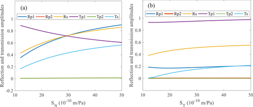
Figure 7 shows the reflection coefficient and transmission coefficient amplitude spectra for the fracture interface at different fracture compliance values. When the incident angle is 30°, the variations in the reflection and transmission amplitudes are in a compliance range of 10−50×10−10 m/Pa (Fig. 7a). With an increase in the normal compliance, SN the reflection coefficient of the fast P-wave increases, while that of the transmission coefficient decreases. In addition, the reflection and transmission amplitudes of the S-waves increase. The reflection and transmission amplitudes of slow P-waves remain essentially unchanged. With an increase in the tangential compliance ST, the reflection coefficient of the fast P-waves first decreases and then increases, while the transmission coefficient increases slowly. In addition, the S-wave reflection and transmission amplitudes both increases. The reflection and transmission amplitudes of the slow P-waves remain essentially unchanged. Therefore, a change in fracture compliance has major influence on the fast P- and S-waves, but little influence on the slow P-waves. Normal and tangential compliance have consistent effects on the reflection coefficient of the S-waves. Fracture compliance parameters can be used as indicators of fluid in fractures, i.e., the reflection amplitudes of the fast P- and S-waves are sensitive to the presence of fluid, which provides a theoretical basis for the inversion of fracture compliance parameters from seismic data.
Details are in the caption following the image
Reflection and transmission amplitudes of the fracture interface at different fracture compliance values.

The pore structure in the actual rock is complicated, and the fluid flow in the pore structure is also complicated. When seismic waves propagate in two-phase media, Biot flow and squirt-flow are the main forms of fluid flow in porous media. Biot flow has a macroscopic nature, and it is difficult to provide a reasonable explanation for the strong attenuation and high frequency dispersion in many rocks. It is necessary to consider the jet flow (local motion) of the fluid. Dvorkin and Nur (1993) proposed to combine the Biot mechanism with the squirt-flow mechanism (Mavko & Nur, 1975). They act as a coupling process to affect wave attenuation and dispersion. When the two attenuation mechanisms are combined, since the P-wave exhibits strong attenuation, it is difficult to observe the slow P-wave in the wave field snapshot, which is not conducive to our analysis of the seismic wave propagation in the two-phase fractured medium. Only under the action of macroscopic Biot flow can the propagation mode of slow P-waves be observed, which is convenient for observing the wave field of seismic waves at the fracture interface. After fully understanding the seismic wave propagation of the fracture interface in the two-phase medium, future studies can add squirt-flow in addition to Biot flow, which can better describe the structure of underground fractures.

CONCLUSION

In this study, a new numerical simulation scheme and the Zoeppritz equation with linear slip boundary conditions are derived. In the numerical simulation scheme, the linear slip fracture interface is introduced into the stiffness matrix of the two-phase medium, which can describe the propagation of seismic waves in a two-phase fractured medium. The fractures can also result in the reflection of seismic waves. The long-term stability of the scheme is tested, proving that the scheme is accurate and stable. The linear slip fracture boundary condition is introduced into the conventional Zoeppritz equation, and the law of seismic wave energy distribution at the fracture interface in the two-phase medium is obtained. The relationship between the reflection coefficient, transmission coefficient, incident angle and fracture compliance is studied based on this equation. Numerically, the fast P-wave reflection coefficient of the two-phase fractured medium is the sum of the impedance and fracture reflection coefficients. Therefore, the new equation can describe the fracture properties independently, and it is not necessary to describe the fractured medium as an anisotropic equivalent medium. Thus, the new numerical simulation scheme and the new Zoeppritz equation can be used to estimate the fracture and rock properties in the medium to more accurately describe the underground structure and fracture properties. Under the Biot flow mechanism, slow P-waves can be observed better, which is convenient for the study of seismic wave propagation in two-phase fractured media. In subsequent research, another important attenuation mechanism, namely squirt-flow mechanism, can be considered. Combining the two mechanisms and studying the seismic wave propagation of fractures under the two mechanisms can further describe the structure of underground fractures.

APPENDIX A

In two-phase fractured media, six kinds of waves will be generated when P-waves incident from the background media to the horizontal fracture interface at α1 angle. It includes incident P-wave, two reflected P-wave, reflected S-wave, two transmitted P-wave and transmitted S-wave.

Figure A.1. Reflection and transmission on fracture interface

The expressions for their plane wave potentials are as follows:
φ 1 s = A p 1 exp i ω t l 1 x sin α 1 + z cos α 1 φ 1 f = B p 1 exp i ω t l 1 x sin α 1 + z cos α 1 φ p 11 s = A p 11 exp i ω t l 11 x sin α 11 z cos α 11 φ p 11 f = B p 11 exp i ω t l 11 x sin α 11 z cos α 11 φ p 12 s = A p 12 exp i ω t l 12 x sin α 12 z cos α 12 φ p 12 f = B p 12 exp i ω t l 12 x sin α 12 z cos α 12 ψ s 1 s = A s 1 exp i ω t l s 1 x sin β 1 z cos β 1 ψ s 1 f = B s 1 exp i ω t l s 1 x sin β 1 z cos β 1 φ p 21 s = A p 21 exp i ω t l 21 x sin α 21 + z cos α 21 φ p 21 f = B p 21 exp i ω t l 21 x sin α 21 + z cos α 21 φ p 22 s = A p 22 exp i ω t l 22 x sin α 22 + z cos α 22 φ p 22 f = B p 22 exp i ω t l 22 x sin α 22 + z cos α 22 ψ s 2 s = A s 2 exp i ω t l s 2 x sin β 2 + z cos β 2 ψ s 2 f = B s 2 exp i ω t l s 2 x sin β 2 + z cos β 2 , \begin{equation} \def\eqcellsep{&}\begin{array}{l} \varphi _1^s = {A_{{p_1}}}\exp i\left[ {\omega t - {l_1}\left( {x\sin {\alpha _1} + z\cos {\alpha _1}} \right)} \right]\\ \varphi _1^f = {B_{{p_1}}}\exp i\left[ {\omega t - {l_1}\left( {x\sin {\alpha _1} + z\cos {\alpha _1}} \right)} \right]\\ \varphi _{{p_{11}}}^s = {A_{{p_{11}}}}\exp i\left[ {\omega t - {l_{11}}\left( {x\sin {\alpha _{11}} - z\cos {\alpha _{11}}} \right)} \right]\\ \varphi _{{p_{11}}}^f = {B_{{p_{11}}}}\exp i\left[ {\omega t - {l_{11}}\left( {x\sin {\alpha _{11}} - z\cos {\alpha _{11}}} \right)} \right]\\ \varphi _{{p_{12}}}^s = {A_{{p_{12}}}}\exp i\left[ {\omega t - {l_{12}}\left( {x\sin {\alpha _{12}} - z\cos {\alpha _{12}}} \right)} \right]\\ \varphi _{{p_{12}}}^f = {B_{{p_{12}}}}\exp i\left[ {\omega t - {l_{12}}\left( {x\sin {\alpha _{12}} - z\cos {\alpha _{12}}} \right)} \right]\\ \psi _{{s_1}}^s = {A_{{s_1}}}\exp i\left[ {\omega t - {l_{s1}}\left( {x\sin {\beta _1} - z\cos {\beta _1}} \right)} \right]\\ \psi _{{s_1}}^f = {B_{{s_1}}}\exp i\left[ {\omega t - {l_{s1}}\left( {x\sin {\beta _1} - z\cos {\beta _1}} \right)} \right]\\ \varphi _{{p_{21}}}^s = {A_{{p_{21}}}}\exp i\left[ {\omega t - {l_{21}}\left( {x\sin {\alpha _{21}} + z\cos {\alpha _{21}}} \right)} \right]\\ \varphi _{{p_{21}}}^f = {B_{{p_{21}}}}\exp i\left[ {\omega t - {l_{21}}\left( {x\sin {\alpha _{21}} + z\cos {\alpha _{21}}} \right)} \right]\\ \varphi _{{p_{22}}}^s = {A_{{p_{22}}}}\exp i\left[ {\omega t - {l_{22}}\left( {x\sin {\alpha _{22}} + z\cos {\alpha _{22}}} \right)} \right]\\ \varphi _{{p_{22}}}^f = {B_{{p_{22}}}}\exp i\left[ {\omega t - {l_{22}}\left( {x\sin {\alpha _{22}} + z\cos {\alpha _{22}}} \right)} \right]\\ \psi _{{s_2}}^s = {A_{{s_2}}}\exp i\left[ {\omega t - {l_{s2}}\left( {x\sin {\beta _2} + z\cos {\beta _2}} \right)} \right]\\ \psi _{{s_2}}^f = {B_{{s_2}}}\exp i\left[ {\omega t - {l_{s2}}\left( {x\sin {\beta _2} + z\cos {\beta _2}} \right)} \right], \end{array} \end{equation} (A-1)
where φ s $\varphi ^s$ and φ f $\varphi ^f$ are the P-wave potentials for the solid and fluid, respectively, and ψ s $\psi ^s$ and ψ f $\psi ^f$ are the S-wave potentials. A and B are the potential amplitudes for the solid and liquid phases, respectively. ω is the circular frequency, l is the circular wavenumber, x and z are the spatial coordinates, and α and β are the wave angles, as shown in Figure A.1.
The boundary conditions at the interface are displacement discontinuity and stress continuity. Therefore, the boundary conditions of vertically fractured media can be written as
u z + = u z + S N τ z z u x + = u x + S T τ x z τ z z + ς + = τ z z + ς τ x z + = τ x z ϕ u z U z + = ϕ u z U z 1 ϕ Q e + R ε + = 1 ϕ Q e + R ε . \begin{equation}\left\{ \def\eqcellsep{&}\begin{array}{l} {\left[ {{u_z}} \right]^ + } = {\left[ {{u_z}} \right]^ - } + {S_N}{\tau _{zz}}\\ {\left[ {{u_x}} \right]^ + } = {\left[ {{u_x}} \right]^ - } + {S_T}{\tau _{xz}}\\ {\left[ {{\tau _{zz}} + \varsigma } \right]^ + } = {\left[ {{\tau _{zz}} + \varsigma } \right]^ - }\\ {\left[ {{\tau _{xz}}} \right]^ + } = {\left[ {{\tau _{xz}}} \right]^ - }\\ {\left[ {\phi \left( {{u_z} - {U_z}} \right)} \right]^ + } = {\left[ {\phi \left( {{u_z} - {U_z}} \right)} \right]^ - }\\ {\left[ {\frac{1}{\phi }\left( {Qe + R\varepsilon } \right)} \right]^ + } = {\left[ {\frac{1}{\phi }\left( {Qe + R\varepsilon } \right)} \right]^ - }. \end{array} \right. \end{equation} (A-2)
In the two-dimensional plane, the displacement of the particle vibration during the propagation of the seismic wave can be expressed as
u x = φ x ψ z u z = φ z + ψ x , \begin{equation}\left\{ { \def\eqcellsep{&}\begin{array}{@{}*{1}{c}@{}} {{u_x} = \frac{{\partial \varphi }}{{\partial x}} - \frac{{\partial \psi }}{{\partial z}}}\\ {{u_z} = \frac{{\partial \varphi }}{{\partial z}} + \frac{{\partial \psi }}{{\partial x}}}, \end{array} } \right. \end{equation} (A-3)
where φ and ψ are potential functions. We assume that the ‘total’ potential function is the sum of the solid and fluid potential functions. Therefore, φ = φ s + φ f $\varphi = {\varphi ^s} + {\varphi ^f}$ represents the total potential function of the P-wave and ψ = ψ s + ψ f $\psi = {\psi ^s} + {\psi ^f}$ represents the total potential function of the S-wave. The displacement u of the particle is decomposed into the gradient of the scalar potential and the curl of its vector potential, u = grad φ + rot ψ ${{\bf u}} = {\rm{grad}}\,\varphi + {\rm{rot}}\,{{\bm \psi }}$ , where ψ = ( 0 , ψ , 0 ) ${{\bm \psi }} = (0,\psi ,0)$ . When studying the plane wave propagating in space, the rectangular coordinate system is generally selected and let / y = 0 $\partial /\partial y = 0$ . Then formula (A-3) can be obtained. This shows that the displacement component in the x - z plane contains μx and μz, which are only related to φ and ψ and contain the components of P-wave and SV-wave.
In the two-dimensional case, according to the relationship between stress and strain described by Hooke's law, we get
τ z z = λ ρ 1 v p 2 2 φ t 2 + 2 μ 2 φ z 2 + 2 ψ z x , \begin{equation}{\tau _{zz}} = \lambda \rho \frac{1}{{v_p^2}}\frac{{{\partial ^2}\varphi }}{{\partial {t^2}}} + 2\mu \left( {\frac{{{\partial ^2}\varphi }}{{\partial {z^2}}} + \frac{{{\partial ^2}\psi }}{{\partial z\partial x}}} \right),\end{equation} (A-4)
τ z x = μ e z x = μ ( u z x + u x z ) = μ ( 2 2 φ x z + 2 ψ x 2 2 ψ z 2 ) . \begin{eqnarray}{\tau _{zx}} &&= \mu {e_{zx}} = \mu (\frac{{\partial {u_z}}}{{\partial x}} + \frac{{\partial {u_x}}}{{\partial z}}) = \mu (2\frac{{{\partial ^2}\varphi }}{{\partial x\partial z}} + \frac{{{\partial ^2}\psi }}{{\partial {x^2}}} - \frac{{{\partial ^2}\psi }}{{\partial {z^2}}}).\nonumber\\ \end{eqnarray} (A-5)
Next, we analyse the six boundary conditions separately. According to the tangential displacement discontinuity [ u z ] + = [ u z ] + S N τ z z ${[ {{u_z}} ]^ + } = {[ {{u_z}} ]^ - } + {S_N}{\tau _{zz}}$ , and the formula (A-1)–(A-5), we get
A p 11 A p 1 v p 1 v p 11 cos α 11 + A p 12 A p 1 v p 1 v p 12 cos α 12 A s 1 A p 1 v p 1 v s 1 sin β 1 + A p 21 A p 1 v p 1 v p 21 cos α 21 i S N λ l 21 i S N 2 μ cos 2 α 21 + A p 22 A p 1 v p 1 v p 22 cos α 22 i S N λ l 22 A s 2 A p 1 v p 1 v s 2 sin β 2 + i S N μ l s 2 sin 2 β 2 = cos α 1 . \begin{equation} \def\eqcellsep{&}\begin{array}{l} \frac{{{A_{{p_{11}}}}}}{{{A_{p1}}}}\frac{{{v_{p1}}}}{{{v_{{p_{11}}}}}}\cos {\alpha _{11}} + \frac{{{A_{{p_{12}}}}}}{{{A_{p1}}}}\frac{{{v_{p1}}}}{{{v_{{p_{12}}}}}}\cos {\alpha _{12}} - \frac{{{A_{{s_1}}}}}{{{A_{p1}}}}\frac{{{v_{p1}}}}{{{v_{{s_1}}}}}\sin {\beta _1} \\[6pt]+ \frac{{{A_{{p_{21}}}}}}{{{A_{p1}}}}\frac{{{v_{p1}}}}{{{v_{{p_{21}}}}}}\left( \def\eqcellsep{&}\begin{array}{l} \cos {\alpha _{21}} - i{S_N}\lambda {l_{21}} - i{S_N}2\mu {\cos ^2}{\alpha _{21}} \end{array} \right)\\[6pt] + \frac{{{A_{{p_{22}}}}}}{{{A_{p1}}}}\frac{{{v_{p1}}}}{{{v_{{p_{22}}}}}}\left( {\cos {\alpha _{22}} - i{S_N}\lambda {l_{22}}} \right)\\[6pt] - \frac{{{A_{{s_2}}}}}{{{A_{p1}}}}\frac{{{v_{p1}}}}{{{v_{{s_2}}}}}\left( {\sin {\beta _2} + i{S_N}\mu {l_{s2}}\sin 2{\beta _2}} \right) = \cos {\alpha _1}. \end{array} \end{equation} (A-6)
According to the discontinuity of tangential displacement [ u x ] + = [ u x ] + S T τ x z ${[ {{u_x}} ]^ + } = {[ {{u_x}} ]^ - } + {S_T}{\tau _{xz}}$ , we get
A p 11 A p 1 v p 1 v p 11 sin α 11 + A p 12 A p 1 v p 1 v p 12 sin α 12 + A s 1 A p 1 v p 1 v s 1 cos β 1 A p 21 A p 1 v p 1 v p 21 sin α 21 i S T μ l 21 sin 2 α 21 A p 22 A p 1 v p 1 v p 22 sin α 22 i S T μ l 22 sin 2 α 22 A s 2 A p 1 v p 1 v s 2 cos β 2 i S T μ l s 2 cos 2 β 2 = sin α 1 . \begin{equation} \def\eqcellsep{&}\begin{array}{l} \frac{{{A_{{p_{11}}}}}}{{{A_{p1}}}}\frac{{{v_{p1}}}}{{{v_{{p_{11}}}}}}\sin {\alpha _{11}} + \frac{{{A_{{p_{12}}}}}}{{{A_{p1}}}}\frac{{{v_{p1}}}}{{{v_{{p_{12}}}}}}\sin {\alpha _{12}} + \frac{{{A_{{s_1}}}}}{{{A_{p1}}}}\frac{{{v_{p1}}}}{{{v_{{s_1}}}}}\cos {\beta _1}\\[6pt] - \frac{{{A_{{p_{21}}}}}}{{{A_{p1}}}}\frac{{{v_{p1}}}}{{{v_{{p_{21}}}}}}\left( \def\eqcellsep{&}\begin{array}{l} \sin {\alpha _{21}}\\[6pt] - i{S_T}\mu {l_{21}}\sin 2{\alpha _{21}} \end{array} \right)\\[6pt] - \frac{{{A_{{p_{22}}}}}}{{{A_{p1}}}}\frac{{{v_{p1}}}}{{{v_{{p_{22}}}}}}\left( {\sin {\alpha _{22}} - i{S_T}\mu {l_{22}}\sin 2{\alpha _{22}}} \right)\\[6pt] - \frac{{{A_{{s_2}}}}}{{{A_{p1}}}}\frac{{{v_{p1}}}}{{{v_{{s_2}}}}}\left( \def\eqcellsep{&}\begin{array}{l} \cos {\beta _2}\\[6pt] - i{S_T}\mu {l_{s2}}\cos 2{\beta _2} \end{array} \right) = - \sin {\alpha _1}. \end{array} \end{equation} (A-7)
According to the normal stress continuous [ τ z z + s ] + = [ τ z z + s ] ${[ {{\tau _{zz}} + s} ]^ + } = {[ {{\tau _{zz}} + s} ]^ - }$ , we get
A p 11 A p 1 v p 1 v p 11 l 11 λ + 2 μ cos 2 α 11 + Q + R + Q B p 11 A p 11 + A p 12 A p 1 v p 1 v p 12 l 12 λ + 2 μ cos 2 α 12 + Q + R + Q B p 12 A p 12 A s 1 A p 1 v p 1 v s 1 l s 1 μ sin 2 β 1 A p 21 A p 1 v p 1 v p 21 l 21 λ + 2 μ cos 2 α 21 + Q + R + Q B p 21 A p 21 A p 22 A p 1 v p 1 v p 22 l 22 λ + 2 μ cos 2 α 22 + Q + R + Q B p 22 A p 22 + A s 2 A p 1 v p 1 v s 2 l s 2 μ sin 2 β 2 = l 1 λ + 2 μ cos 2 α 1 + Q + R + Q B p 1 A p 1 . \begin{eqnarray}&& \frac{{{A_{{p_{11}}}}}}{{{A_{p1}}}}\frac{{{v_{{p_1}}}}}{{{v_{{p_{11}}}}}}{l_{11}}\left( \def\eqcellsep{&}\begin{array}{l} \lambda + 2\mu {\cos ^2}{\alpha _{11}} + \\ Q + \left( {R + Q} \right)\frac{{{B_{p11}}}}{{{A_{p11}}}} \end{array} \right)\nonumber\\ && + \frac{{{A_{{p_{12}}}}}}{{{A_{p1}}}}\frac{{{v_{{p_1}}}}}{{{v_{{p_{12}}}}}}{l_{12}}\left( \def\eqcellsep{&}\begin{array}{l} \lambda + 2\mu {\cos ^2}{\alpha _{12}} + \\ Q + \left( {R + Q} \right)\frac{{{B_{{p_{12}}}}}}{{{A_{{p_{12}}}}}} \end{array} \right)\nonumber\\ &&- \frac{{{A_{{s_1}}}}}{{{A_{p1}}}}\frac{{{v_{{p_1}}}}}{{{v_{{s_1}}}}}{l_{s1}}\mu \sin 2{\beta _1} - \frac{{{A_{{p_{21}}}}}}{{{A_{p1}}}}\frac{{{v_{{p_1}}}}}{{{v_{{p_{21}}}}}}{l_{21}}\left( \def\eqcellsep{&}\begin{array}{l} \lambda + 2\mu {\cos ^2}{\alpha _{21}} + \\ Q + \left( {R + Q} \right)\frac{{{B_{{p_{21}}}}}}{{{A_{{p_{21}}}}}} \end{array} \right)\nonumber\\ &&- \frac{{{A_{{p_{22}}}}}}{{{A_{p1}}}}\frac{{{v_{{p_1}}}}}{{{v_{{p_{22}}}}}}{l_{22}}\left( \def\eqcellsep{&}\begin{array}{l} \lambda + 2\mu {\cos ^2}{\alpha _{22}} + \\ Q + \left( {R + Q} \right)\frac{{{B_{{p_{22}}}}}}{{{A_{{p_{22}}}}}} \end{array} \right) + \frac{{{A_{{s_2}}}}}{{{A_{p1}}}}\frac{{{v_{{p_1}}}}}{{{v_{{s_2}}}}}{l_{s2}}\mu \sin 2{\beta _2}\nonumber\\ && = - {l_1}\left( {\lambda + 2\mu {{\cos }^2}{\alpha _1} + Q + \left( {R + Q} \right)\frac{{{B_{p1}}}}{{{A_{p1}}}}} \right).\nonumber\\ \end{eqnarray} (A-8)
According to the tangential stress continuous [ τ x z ] + = [ τ x z ] ${[ {{\tau _{xz}}} ]^ + } = {[ {{\tau _{xz}}} ]^ - }$ , we get
l 11 A p 11 A p 1 v p 1 v p 11 sin 2 α 11 + l 12 A p 12 A p 1 v p 1 v p 12 sin 2 α 12 + l s 1 A p 11 A s 1 v p 1 v s 1 cos 2 β 1 + l 21 A p 11 A p 21 v p 1 v p 21 sin 2 α 21 + l 22 A p 11 A p 22 v p 1 v p 22 sin 2 α 22 + l s 2 A p 11 A s 2 v p 1 v s 2 cos 2 β 2 = l 1 sin 2 α 1 . \begin{eqnarray}&& {l_{11}}\frac{{{A_{{p_{11}}}}}}{{{A_{p1}}}}\frac{{{v_{{p_1}}}}}{{{v_{{p_{11}}}}}}\sin 2{\alpha _{11}} + {l_{12}}\frac{{{A_{{p_{12}}}}}}{{{A_{p1}}}}\frac{{{v_{{p_1}}}}}{{{v_{{p_{12}}}}}}\sin 2{\alpha _{12}} + {l_{s1}}\frac{{{A_{{p_{11}}}}}}{{{A_{s1}}}}\frac{{{v_{{p_1}}}}}{{{v_{{s_1}}}}}\cos 2{\beta _1}\nonumber\\ && + {l_{21}}\frac{{{A_{{p_{11}}}}}}{{{A_{p21}}}}\frac{{{v_{{p_1}}}}}{{{v_{{p_{21}}}}}}\sin 2{\alpha _{21}} + {l_{22}}\frac{{{A_{{p_{11}}}}}}{{{A_{p22}}}}\frac{{{v_{{p_1}}}}}{{{v_{{p_{22}}}}}}\sin 2{\alpha _{22}}\nonumber\\ && + {l_{s2}}\frac{{{A_{{p_{11}}}}}}{{{A_{s2}}}}\frac{{{v_{{p_1}}}}}{{{v_{{s_2}}}}}\cos 2{\beta _2} = {l_1}\sin 2{\alpha _1} .\end{eqnarray} (A-9)
According to the normal flow continuity [ ϕ ( u z U z ) ] + = [ ϕ ( u z U z ) ] ${[ {\phi ( {{u_z} - {U_z}} )} ]^ + } = {[ {\phi ( {{u_z} - {U_z}} )} ]^ - }$ , we get
1 B p 11 A p 11 A p 11 A p 1 v p 1 v p 11 cos α 11 + 1 B p 12 A p 12 A p 12 A p 1 v p 1 v p 12 cos α 12 1 B s 1 A s 1 A s 1 A p 1 v p 1 v s 1 sin β 1 + 1 B p 21 A p 21 A p 21 A p 1 v p 1 v p 21 cos α 21 + 1 B p 22 A p 22 A p 22 A p 1 v p 1 v p 22 cos α 22 1 + B s 2 A s 2 A s 2 A p 1 v p 1 v s 2 sin β 2 = 1 B p 1 A p 1 cos α 1 . \begin{eqnarray}&& \left( {1 - \frac{{{B_{{p_{11}}}}}}{{{A_{p11}}}}} \right)\frac{{{A_{{p_{11}}}}}}{{{A_{p1}}}}\frac{{{v_{{p_1}}}}}{{{v_{{p_{11}}}}}}\cos {\alpha _{11}}\nonumber\\ &&+ \left( {1 - \frac{{{B_{{p_{12}}}}}}{{{A_{{p_{12}}}}}}} \right)\frac{{{A_{{p_{12}}}}}}{{{A_{p1}}}}\frac{{{v_{{p_1}}}}}{{{v_{{p_{12}}}}}}\cos {\alpha _{12}} - \left( {1 - \frac{{{B_{{s_1}}}}}{{{A_{{s_1}}}}}} \right)\frac{{{A_{{s_1}}}}}{{{A_{p1}}}}\frac{{{v_{{p_1}}}}}{{{v_{{s_1}}}}}\sin {\beta _1}\nonumber\\ &&+ \left( {1 - \frac{{{B_{{p_{21}}}}}}{{{A_{{p_{21}}}}}}} \right)\frac{{{A_{{p_{21}}}}}}{{{A_{p1}}}}\frac{{{v_{{p_1}}}}}{{{v_{{p_{21}}}}}}\cos {\alpha _{21}}\nonumber\\ &&+ \left( {1 - \frac{{{B_{{p_{22}}}}}}{{{A_{{p_{22}}}}}}} \right)\frac{{{A_{{p_{22}}}}}}{{{A_{p1}}}}\frac{{{v_{{p_1}}}}}{{{v_{{p_{22}}}}}}\cos {\alpha _{22}} - \left( {1 + \frac{{{B_{{s_2}}}}}{{{A_{{s_2}}}}}} \right)\frac{{{A_{{s_2}}}}}{{{A_{p1}}}}\frac{{{v_{{p_1}}}}}{{{v_{{s_2}}}}}\sin {\beta _2}\nonumber\\ &&= \left( {1 - \frac{{{B_{p1}}}}{{{A_{p1}}}}} \right)\cos {\alpha _1}. \end{eqnarray} (A-10)
According to the fluid pressure continuous [ 1 ϕ ( Q e + R ε ) ] + = [ 1 ϕ ( Q e + R ε ) ] ${[ {\frac{1}{\phi }( {Qe + R\varepsilon } )} ]^ + } = {[ {\frac{1}{\phi }( {Qe + R\varepsilon } )} ]^ - }$ , we get
A p 11 A p 1 v p 1 v p 11 l 11 Q + R B p 11 A p 11 + A p 12 A p 1 v p 1 v p 12 l 12 Q + R B p 12 A p 12 A p 21 A p 1 v p 1 v p 21 l 21 Q + R B p 21 A p 21 A p 22 A p 1 v p 1 v p 22 l 22 Q + R B p 22 A p 22 = l 1 Q + R B p 1 A p 1 . \begin{eqnarray}&& \frac{{{A_{{p_{11}}}}}}{{{A_{p1}}}}\frac{{{v_{p1}}}}{{{v_{{p_{11}}}}}}{l_{11}}\left( {Q + R\frac{{{B_{{p_{11}}}}}}{{{A_{{p_{11}}}}}}} \right) + \frac{{{A_{{p_{12}}}}}}{{{A_{p1}}}}\frac{{{v_{p1}}}}{{{v_{{p_{12}}}}}}{l_{12}}\left( {Q + R\frac{{{B_{{p_{12}}}}}}{{{A_{{p_{12}}}}}}} \right)\nonumber\\ && - \frac{{{A_{{p_{21}}}}}}{{{A_{p1}}}}\frac{{{v_{p1}}}}{{{v_{{p_{21}}}}}}{l_{21}}\left( {Q + R\frac{{{B_{{p_{21}}}}}}{{{A_{{p_{21}}}}}}} \right) - \frac{{{A_{{p_{22}}}}}}{{{A_{p1}}}}\frac{{{v_{p1}}}}{{{v_{{p_{22}}}}}}{l_{22}}\left( {Q + R\frac{{{B_{{p_{22}}}}}}{{{A_{{p_{22}}}}}}} \right)\nonumber\\ && = - {l_1}\left( {Q + R\frac{{{B_{p1}}}}{{{A_{p1}}}}} \right). \end{eqnarray} (A-11)
Equation (A-6)–(A-11) are known as the Knott equation, which reflects the relationship between the amplitudes of the potential functions of each wave. For the potential function, the reflection coefficient of the fast P-waves is A p 11 A p 1 $\frac{{A{p_{11}}}}{{A{p_1}}}$ . A p 12 A p 1 , A s 1 A p 1 , A p 21 A p 1 , A p 22 A p 1 , and A s 2 A p 1 $\frac{{{A_{{p_{12}}}}}}{{{A_{{p_1}}}}},\,\frac{{{A_{{s_1}}}}}{{{A_{{p_1}}}}},\,\frac{{{A_{{p_{21}}}}}}{{{A_{{p_1}}}}},\,\frac{{{A_{{p_{22}}}}}}{{{A_{{p_1}}}}},\,{\rm{and}}\,\frac{{{A_{{s_2}}}}}{{{A_{{p_1}}}}}$ , which are the reflection coefficient of slow P-waves, the reflection coefficient of S-waves, the transmission coefficient of the fast P-waves, the transmission coefficient of the slow P-waves and the transmission coefficient of the S-waves, respectively. The above reflection and transmission coefficients are in terms of the potential function, and the reflection and transmission coefficients used for displacement satisfy
R p 11 = A p 11 A p 1 v p 1 v p 11 R p 12 = A p 12 A p 1 v p 1 v p 12 R s 1 = A s 1 A p 1 v p 1 v s 1 T p 21 = A p 21 A p 1 v p 1 v p 21 T p 22 = A p 22 A p 1 v p 1 v p 22 T s 2 = A s 2 A p 1 v p 1 v s 2 , \begin{equation} \def\eqcellsep{&}\begin{array}{l} {R_{{p_{11}}}} = \frac{{{A_{{p_{11}}}}}}{{{A_{{p_1}}}}}\frac{{{v_{{p_1}}}}}{{{v_{{p_{11}}}}}}{\rm{ }}{R_{{p_{12}}}} = \frac{{{A_{{p_{12}}}}}}{{{A_{{p_1}}}}}\frac{{{v_{{p_1}}}}}{{{v_{{p_{12}}}}}}{\rm{ }}{R_{{s_1}}} = \frac{{{A_{{s_1}}}}}{{{A_{{p_1}}}}}\frac{{{v_{{p_1}}}}}{{{v_{{s_1}}}}}\\ {T_{{p_{21}}}} = \frac{{{A_{{p_{21}}}}}}{{{A_{{p_1}}}}}\frac{{{v_{{p_1}}}}}{{{v_{{p_{21}}}}}}{\rm{ }}{T_{{p_{22}}}} = \frac{{{A_{{p_{22}}}}}}{{{A_{{p_1}}}}}\frac{{{v_{{p_1}}}}}{{{v_{{p_{22}}}}}}{\rm{ }}{T_{{s_2}}} = \frac{{{A_{{s_2}}}}}{{{A_{{p_1}}}}}\frac{{{v_{{p_1}}}}}{{{v_{{s_2}}}}}{\rm{ }}, \end{array} \end{equation} (A-12)
where R p 11 ${R_{{p_{11}}}}$ , R p 12 ${R_{{p_{12}}}}$ , R s 1 ${R_{{s_1}}}$ , T p 21 ${T_{{p_{21}}}}$ , T p 22 ${T_{{p_{22}}}}$ and T s 2 ${T_{{s_2}}}$ are the reflection coefficient of the fast P-waves expressed by the displacement amplitude, the reflection coefficient of the slow P-waves expressed by the displacement amplitude, the reflection coefficient of the S-waves expressed by the displacement amplitude, the transmission coefficient of the fast P-waves expressed by the displacement amplitude, the transmission coefficient of the slow P-waves expressed by the displacement amplitude and the transmission coefficient of the S-waves expressed by the displacement amplitude. By synthesizing (A-6)–(A-12), we obtain
cos α 11 cos α 12 sin β 1 cos α 21 i S N λ l 21 i S N 2 μ cos 2 α 21 sin α 11 sin α 12 cos β 1 sin α 21 i S T μ l 21 sin 2 α 21 l 11 λ + 2 μ cos 2 α 11 + Q + R + Q B p 11 A p 11 l 12 λ + 2 μ cos 2 α 12 + Q + R + Q B p 12 A p 12 μ l s 1 sin 2 β 1 l 21 λ + 2 μ cos 2 α 21 + Q + R + Q B p 21 A p 21 l 11 sin 2 α 11 l 12 sin 2 α 12 l s 1 cos 2 β 1 l 21 sin 2 α 21 1 B p 11 A p 11 cos α 11 1 B p 12 A p 12 cos α 12 1 + ρ 12 ρ 22 sin β 1 1 B p 21 A p 21 cos α 21 l 11 Q + R B p 11 A p 11 l 11 Q + R B p 11 A p 11 0 l 21 Q + R B p 21 A p 21 cos α 22 i S N λ l 22 sin β 2 + i S N μ l s 2 sin 2 β 2 sin α 22 i S T μ l 22 sin 2 α 22 cos β 2 i S T μ l s 2 cos 2 β 2 l 22 λ + 2 μ l 22 cos 2 α 22 + Q + R + Q B p 22 A p 22 μ l s 2 sin 2 β 2 l 22 sin 2 α 22 l s 2 cos 2 β 2 1 B p 22 A p 22 cos α 22 1 + ρ 12 ρ 22 sin β 2 l 22 Q + R B p 22 A p 22 0 R p 11 R p 12 R s 1 T p 21 T p 22 T s 2 = cos α 1 sin α 1 l 1 λ + 2 μ cos 2 α 1 + Q + R + Q B p 1 A p 1 l 1 sin 2 α 1 1 B p 1 A p 1 cos α 1 l 1 Q + R B p 1 A p 1 . \begin{equation} \def\eqcellsep{&}\begin{array}{l} \left[ { \def\eqcellsep{&}\begin{array}{@{}*{4}{c}@{}} {\cos {\alpha _{11}}}&{\cos {\alpha _{12}}}&{ - \sin {\beta _1}}& \def\eqcellsep{&}\begin{array}{l} \cos {\alpha _{21}} - i{S_N}\lambda {l_{21}}\\ - i{S_N}2\mu {\cos ^2}{\alpha _{21}} \end{array} \\ {\sin {\alpha _{11}}}&{\sin {\alpha _{12}}}&{\cos {\beta _1}}&{ - \left( {\sin {\alpha _{21}} - i{S_T}\mu {l_{21}}\sin 2{\alpha _{21}}} \right)}\\ {{l_{11}}\left( \def\eqcellsep{&}\begin{array}{l} \lambda + 2\mu {\cos ^2}{\alpha _{11}}\\ + Q + \left( {R + Q} \right)\frac{{{B_{p11}}}}{{{A_{p11}}}} \end{array} \right)}&{{l_{12}}\left( \def\eqcellsep{&}\begin{array}{l} \lambda + 2\mu {\cos ^2}{\alpha _{12}}\\ + Q + \left( {R + Q} \right)\frac{{{B_{{p_{12}}}}}}{{{A_{{p_{12}}}}}} \end{array} \right)}&{ - \mu {l_{s1}}\sin 2{\beta _1}}&{ - {l_{21}}\left( \def\eqcellsep{&}\begin{array}{l} \lambda + 2\mu {\cos ^2}{\alpha _{21}}\\ + Q + \left( {R + Q} \right)\frac{{{B_{{p_{21}}}}}}{{{A_{{p_{21}}}}}} \end{array} \right)}\\ {{l_{11}}\sin 2{\alpha _{11}}}&{{l_{12}}\sin 2{\alpha _{12}}}&{{l_{s1}}\cos 2{\beta _1}}&{{l_{21}}\sin 2{\alpha _{21}}}\\ {\left( {1 - \frac{{{B_{{p_{11}}}}}}{{{A_{p11}}}}} \right)\cos {\alpha _{11}}}&{\left( {1 - \frac{{{B_{{p_{12}}}}}}{{{A_{{p_{12}}}}}}} \right)\cos {\alpha _{12}}}&{ - \left( {1 + \frac{{{\rho _{12}}}}{{{\rho _{22}}}}} \right)\sin {\beta _1}}&{\left( {1 - \frac{{{B_{{p_{21}}}}}}{{{A_{{p_{21}}}}}}} \right)\cos {\alpha _{21}}}\\ {{l_{11}}\left( {Q + R\frac{{{B_{{p_{11}}}}}}{{{A_{{p_{11}}}}}}} \right)}&{{l_{11}}\left( {Q + R\frac{{{B_{{p_{11}}}}}}{{{A_{{p_{11}}}}}}} \right)}&0&{ - {l_{21}}\left( {Q + R\frac{{{B_{{p_{21}}}}}}{{{A_{{p_{21}}}}}}} \right)} \end{array} } \right.\\ \\ \left. { \def\eqcellsep{&}\begin{array}{@{}*{2}{c}@{}} {\cos {\alpha _{22}} - i{S_N}\lambda {l_{22}}}&{ - \left( {\sin {\beta _2} + i{S_N}\mu {l_{s2}}\sin 2{\beta _2}} \right)}\\ { - \left( {\sin {\alpha _{22}} - i{S_T}\mu {l_{22}}\sin 2{\alpha _{22}}} \right)}&{ - \left( {\cos {\beta _2} - i{S_T}\mu {l_{s2}}\cos 2{\beta _2}} \right)}\\ { - {l_{22}}\left( \def\eqcellsep{&}\begin{array}{l} \lambda + 2\mu {l_{22}}{\cos ^2}{\alpha _{22}}\\ + Q + \left( {R + Q} \right)\frac{{{B_{{p_{22}}}}}}{{{A_{{p_{22}}}}}} \end{array} \right)}&{\mu {l_{s2}}\sin 2{\beta _2}}\\ {{l_{22}}\sin 2{\alpha _{22}}}&{{l_{s2}}\cos 2{\beta _2}}\\ {\left( {1 - \frac{{{B_{{p_{22}}}}}}{{{A_{{p_{22}}}}}}} \right)\cos {\alpha _{22}}}&{ - \left( {1 + \frac{{{\rho _{12}}}}{{{\rho _{22}}}}} \right)\sin {\beta _2}}\\ { - {l_{22}}\left( {Q + R\frac{{{B_{{p_{22}}}}}}{{{A_{{p_{22}}}}}}} \right)}&0 \end{array} } \right]\left[ { \def\eqcellsep{&}\begin{array}{@{}*{1}{c}@{}} {{R_{{p_{11}}}}}\\ {{R_{{p_{12}}}}}\\ {{R_{{s_1}}}}\\ {{T_{{p_{21}}}}}\\ {{T_{{p_{22}}}}}\\ {{T_{{s_2}}}} \end{array} } \right] = \left[ { \def\eqcellsep{&}\begin{array}{@{}*{1}{c}@{}} {\cos {\alpha _1}}\\ { - \sin {\alpha _1}}\\ { - {l_1}\left( \def\eqcellsep{&}\begin{array}{l} \lambda + 2\mu {\cos ^2}{\alpha _1}\\ + Q + \left( {R + Q} \right)\frac{{{B_{p1}}}}{{{A_{p1}}}} \end{array} \right)}\\ {{l_1}\sin 2{\alpha _1}}\\ {\left( {1 - \frac{{{B_{p1}}}}{{{A_{p1}}}}} \right)\cos {\alpha _1}}\\ { - {l_1}\left( {Q + R\frac{{{B_{p1}}}}{{{A_{p1}}}}} \right)} \end{array} } \right]. \end{array} \end{equation} (A-13)

This set of equations (A-13) is known as the Zoeppritz equations. To ensure the correctness of the equation, it can be compared with the degenerate equation. First, in a two-phase fractured medium with an impedance contrast (the impedance contrast and the fracture interfaces are located at the same position), when the fracture compliance parameter is zero (i.e. the fracture does not exist), equations (A6)–(A11) can be decomposed to the Zoeppritz equations of a traditional two-phase medium (Lin et al., 2014). This indicates that the equation of the two-phase background medium is correct when the fracture does not exist. This also indicates that the contributions of fractures to the reflection and transmission coefficients are displayed explicitly. In other words, in a two-phase fractured medium with an impedance contrast, the reflection at the interface can be divided into the reflection caused by the fracture and the reflection at the impedance interface. Second, when the porosity of the background medium is zero, the two-phase fractured medium becomes homogeneous fractured medium. Equation (A-13) degenerates to the Zoeppritz equation of homogeneous fractured medium. This is consistent with the result obtained by Schoenberg (1980) (formula (26) in Schoenberg's article) and shows that the equation for the fracture part is correct when the background is a homogeneous medium. The formula (A-13) includes the background medium part and the fracture part. Therefore, the correctness of the equations can be guaranteed through two degenerate equations:

Equations (A-13) describe the Zoeppritz equation for two-phase horizontal fracture. When the fracture is vertical, six types of waves will also be generated when a P-wave is incident from a two-phase background medium to the fracture interface. The boundary conditions of the fracture interface are changed to discontinuous normal displacement of solid [ u x ] + = [ u x ] + S N τ x x ${[ {{u_x}} ]^ + } = {[ {{u_x}} ]^ - } + {S_N}{\tau _{xx}}$ and discontinuous tangential displacement of solid [ u z ] + = [ u z ] + S T τ z x ${[ {{u_z}} ]^ + } = {[ {{u_z}} ]^ - } + {S_T}{\tau _{zx}}$ . Then calculations were perform to obtain the Zoeppritz equation of the two-phase vertical fracture.

APPENDIX B

For two-phase isotropic media, it is difficult to obtain many parameters directly from seismic data. The relationship between six parameters and two-phase elastic parameters A, N, Q and R can be established by using rock-physical relationship, including P-wave velocity v p ${v_p}$ , S-wave velocity v s ${v_s}$ , density ρ, porosity ϕ, fluid velocity v f ${v_f}$ and fluid density ρ f ${\rho _f}$ . These six parameters can be obtained directly from seismic data.

The three density parameters can be determined using the following formulas (Berryman, 1980):
ρ 12 = 1 χ φ ρ f ρ 22 = ϕ ρ f ρ 12 ρ 11 = 1 ϕ ρ s ρ 12 ρ s = ρ ϕ ρ f / 1 ϕ . \begin{equation} \def\eqcellsep{&}\begin{array}{l} {\rho _{12}} = \left( {1 - \chi } \right)\varphi {\rho _f}\\ {\rho _{22}} = \phi {\rho _f} - {\rho _{12}}\\ {\rho _{11}} = \left( {1 - \phi } \right){\rho _s} - {\rho _{12}}\\ {\rho _s} = \left( {\rho - \phi {\rho _f}} \right)/\left( {1 - \phi } \right). \end{array} \end{equation} (B-1)
where κ = 1 χ ( 1 1 / ϕ ) $\kappa = 1 - \chi (1 - 1/\phi )$ is the tortuosity parameter. Berryman (1981) pointed out that when the solid particles are spheres, χ = 0.5 $\chi = 0.5$ . For other ellipsoidal shapes, it is between 0 and 1. Mou (1996) gave empirical formula ρ 12 = 0.5 φ ρ f ${\rho _{12}} = - 0.5\varphi {\rho _f}$ . For convenience, we use this empirical formula.
A and N can be determined according to the P-wave velocity, S-wave velocity and density. A is equivalent to the Lamé parameter λ, where A = λ = ρ ( ν p 2 2 ν s 2 ) $A = \lambda = \rho (\nu _p^2 - 2\nu _s^2)$ . N is equivalent to the Lamé parameter μ, where N = μ = ρ v s 2 $N = \mu = \rho v_s^2$ . Next, the derivation of Q and R is given. Q = K ϕ R $Q = K\phi - R$ is the coupling coefficient of the volume change between the solid and liquid phases. R = L ϕ 2 $R = L{\phi ^2}$ is the elastic parameter that describes the pore fluid. Since the porosity is known, K and L need to be obtained. According to Geertsma & Smit (1961),
L = 1 1 ϕ β C r + ϕ C f K = 1 β 1 ϕ β C r + ϕ C f , \begin{equation} \def\eqcellsep{&}\begin{array}{l} L = \frac{1}{{\left( {1 - \phi - \beta } \right){C_r} + \phi {C_f}}}\\ K = \frac{{1 - \beta }}{{\left( {1 - \phi - \beta } \right){C_r} + \phi {C_f}}}, \end{array} \end{equation} (B-2)
where β = C r / C b $\beta = {C_r}/{C_b}$ , C r = 1 / K r ${C_r} = 1/{K_r}$ is the compressibility of the framework particles of the two-phase medium, C b = 1 / K b ${C_b} = 1/{K_b}$ is the compressibility of dry rock, and C f = 1 / K f ${C_f} = 1/{K_f}$ is the fluid compressibility.
To obtain L and K, K b ${K_b}$ , K f ${K_f}$ and K r ${K_r}$ must first be obtained, where K f = ρ v f 2 ${K_f} = \rho v_f^2$ is the bulk modulus of the fluid. According to Berryman's (1980) self-consistent theory:
C i K i K m P i = 0 C i μ i μ m Q i = 0 , \begin{equation} \def\eqcellsep{&}\begin{array}{l} \sum {{C_i}\left( {{K_i} - {K_m}} \right)} {P_i} = 0\\ \sum {{C_i}\left( {{\mu _i} - {\mu _m}} \right)} {Q_i} = 0, \end{array} \end{equation} (B-3)
where C i ${C_i}$ is the volume percentage of each component; K i ${K_i}$ and μ i ${\mu _i}$ are the bulk and shear moduli of each component, and K m = λ + 2 3 μ ${K_m} = \lambda + \frac{2}{3}\mu $ (where μ m = ρ v s 2 ${\mu _m} = \rho v_s^2$ ) is the equivalent elastic parameter of the saturated fluid two-phase medium. If only one solid phase and fluid phase are investigated, then equation (B-3) can be written as
ϕ K f K m P f + 1 ϕ K r K m P r = 0 ϕ μ f μ m P f + 1 ϕ μ r μ m Q r = 0 . \begin{equation} \def\eqcellsep{&}\begin{array}{l} \phi \left( {{K_f} - {K_m}} \right){P_f} + \left( {1 - \phi } \right)\left( {{K_r} - {K_m}} \right){P_r} = 0\\ \phi \left( {{\mu _f} - {\mu _m}} \right){P_f} + \left( {1 - \phi } \right)\left( {{\mu _r} - {\mu _m}} \right){Q_r} = 0. \end{array} \end{equation} (B-4)

It can be assumed that P i = K m + 4 3 μ m K i + 4 3 μ m ${P_i} = \frac{{{K_m} + \frac{4}{3}{\mu _m}}}{{{K_i} + \frac{4}{3}{\mu _m}}}$ and Q i = μ m + μ m 6 9 K m + 8 μ m K m + 2 μ m μ i + μ m 6 9 K m + 8 μ m K m + 2 μ m ${Q_i} = \frac{{{\mu _m} + \frac{{{\mu _m}}}{6}\frac{{9{K_m} + 8{\mu _m}}}{{{K_m} + 2{\mu _m}}}}}{{{\mu _i} + \frac{{{\mu _m}}}{6}\frac{{9{K_m} + 8{\mu _m}}}{{{K_m} + 2{\mu _m}}}}}$ . The iterative solution to equation (B-4) can be used to obtain the bulk moduli K r ${K_r}$ and μ r ${\mu _r}$ of the framework particles.

The bulk modulus of the dry rock skeleton K b ${K_b}$ can be obtained by substituting K m ${K_m}$ , K r ${K_r}$ and K f ${K_f}$ into the Gassmann equation (1951):
K b = K m ϕ K r K f + 1 ϕ K r ϕ K r K f + K K r 1 ϕ . \begin{equation}{K_b} = \frac{{{K_m}\left( {\frac{{\phi {K_r}}}{{{K_f}}} + 1 - \phi } \right) - {K_r}}}{{\frac{{\phi {K_r}}}{{{K_f}}} + \frac{K}{{{K_r}}} - 1 - \phi }}.\end{equation} (B-5)

K b ${K_b}$ , K r ${K_r}$ and K f ${K_f}$ are substituted into equation (1) to obtain the expressions for L and K, and subsequently the expressions for Q and R. Thus far, A, N, Q and R have been obtained.

DATA AVAILABILITY STATEMENT

The data that support the findings of this study are available from the corresponding author upon reasonable request.

    The full text of this article hosted at iucr.org is unavailable due to technical difficulties.