Humidity-Resistant Ultralow Friction in Diamond-Like Carbon Coatings Enabled by Graphitic Nanodiamonds
Abstract
Hydrogenated diamond-like carbon (H-DLC) coatings are extensively employed in high-performance tribological applications, yet their frictional behavior in humid environments remains a critical limitation. A scalable and industrially viable strategy based on graphitic nanodiamonds (Gr-NDs) is here proposed, enabling humidity-resistant ultralow friction (coefficient of friction <0.1) without requiring controlled atmospheres or complex surface treatments. This approach is distinct from many recent methods involving the deposition of nanoparticles and 2D materials, which often fail under humid conditions. Gr-NDs leverage their intrinsic core–shell nanostructure to promote the in operando formation of a peculiar graphitic transfer layer (TL), directly enhancing interfacial lubrication. High-resolution transmission electron microscopy and Raman spectroscopy confirm that these nanostructures are effectively retained within the TL, ensuring superior wear resistance and friction reduction. Furthermore, spectroscopic analysis reveals that moderate tribochemical oxidation stabilizes the TL, extending its durability under realistic operating conditions. This work establishes Gr-NDs as a disruptive functional additive for H-DLC coatings, offering a robust, scalable, and environmentally friendly solution for next-generation tribological systems in demanding mechanical applications.
1 Introduction
Hydrogenated diamond-like carbon (H-DLC) coatings are widely recognized for their exceptional tribological properties, including low friction, high wear resistance, and chemical stability.[1-5] These features, together with the relatively low-cost technology on an industrial scale, allow their application in optoelectronic equipment, as coating layer for electrochemical electrode material or protective coating layer for tribological or chemical applications; not only, DLC-based coatings can find applications as cold-cathode materials, as components in optical devices, up to automotive parts and tools.[6-10] Recent advancements on mechanical applications have focused on functionalizing DLC substrates with nanomaterials such as nanoparticles (NPs) and 2D materials, used alone or in combination, to substantially enhance the tribological response of DLC and reach the ultralow friction regime which is typically characterized by a coefficient of friction (CoF) below 0.1. Performance improvement is generally achieved by functionalization procedures involving chemically and/or morphologically multi-element materials responsible for the formation of a peculiar transfer layer (TL) able to simultaneously protect the counterpart and to confer higher lubricity to the system.[11-16] This is because the tribological and mechanical properties of carbon-based 2D materials, such as graphene, are widely recognized for their ability to reduce friction and enhance wear resistance,[17-21] making them particularly relevant for the functionalization of DLC coatings. However, the use of graphene alone has shown limitations, particularly in terms of long-term stability and adhesion to the DLC matrix, which can affect its effectiveness in demanding tribological conditions. These constraints have led to exploring new processes that synergistically use 2D materials and NPs.
The key element seems to be the presence of nanostructures arranged in a core–shell way, consisting of a hard and small core wrapped by self-lubricating multi-layered 2D materials, as firstly highlighted by Berman et al.[22] In their seminal paper, these authors considered the case of a DLC-coated ball sliding against graphene-coated ultraflat substrates in a dry atmosphere, and with the addition of nanodiamonds (NDs) they demonstrated the achievement of stable macroscale superlubricity thanks to the formation of graphene nanoscroll structures, namely few-layers graphene wrapped around the small (<5 nm) ND core. Macroscale superlubricity can be achieved also via tribochemical pathways; for example, Sumant et al.[23] have shown that high shear stress and contact pressure, in the presence of 2D layers of molybdenum disulfide (MoS2) combined with NDs against (H-DLC), promote NDs amorphization in a dry atmosphere, through strain-induced diffusion of sulfur atoms, forming carbon onion-like structures. In a way very similar to graphene nanoscrolls, these nanostructures enable the reduction of contact area, providing an incommensurate contact with the inert H-DLC surface.
Other tribochemical mechanisms recently proposed, entailed the formation at the sliding interface of onion-like nanostructures from graphene patches wrapped around iron NPs (Fe-NPs).[24] In this case both the high contact pressure, the shear, and the local temperature increment led to carbon graphitization and, eventually, to carbon onion-like structures. Interestingly, no superlubricity was observed when graphene is combined with iron oxide (Fe2O3) NPs, thus suggesting how the intimate core–shell contact plays a crucial role in improving tribological behavior.[24] Recent studies have explored combinations of NPs and different 2D nanosheets to enhance the tribological performance of DLC coatings. Bai et al.[25] demonstrated that hexagonal boron nitride (h-BN) nanosheets wrapped around carbon NPs (CNPs) significantly improve DLC coating performances. Similarly, Huang et al. achieved superlubricity in dry nitrogen both on H-DLC[26] and nonhydrogenated DLC[27] by combining NDs with h-BN nanoflakes in a core–shell structure. A high-vacuum thermal treatment between 80 and 200 °C was necessary to stabilize the NDs and h-BN core–shell structure on the DLC surface before tribological tests.
Despite these advancements, current approaches rely on complex functionalization steps, heteroatom nanostructures, vacuum-thermal treatments, or precisely engineered atomic structures, all of which are challenges that hinder scalability for industrial applications. Moreover, extremely good performances are obtained typically in dry environments, and using ultraflat substrates. Thus, although these methods demonstrate exceptional tribological improvements, their effectiveness under realistic sliding conditions has yet to be proven. In this respect, a first step forward was recently achieved by some of the authors.[28] They demonstrated the efficiency of a similar functionalization procedure even on microrough DLC coatings, produced at an industrial level through plasma-assisted chemical vapor deposition (PA-CVD), where the ultralow friction regime was achieved in a dry atmosphere as a result of the formation of a TL on the steel counterpart that included graphene nanoscroll structures.[28]
In this work, we propose a novel approach based on the functionalization of microrough DLC coatings produced at an industrial level with graphitic NDs (Gr-NDs), a presynthesized core–shell nanostructure consisting of ND cores wrapped in few-layer graphene. Unlike previous strategies, the pre-existing core–shell configuration of Gr-NDs enables the direct formation of a peculiar lubricating TL that assures ultralow friction (CoF < 0.1) even in standard humidity conditions, i.e., relative humidity between 50% and 60% (RH 50%–60%). To validate this mechanism, a comprehensive experimental investigation combining tribological tests with high-resolution characterization techniques is performed. In particular, Raman spectroscopy, transmission electron microscopy (TEM), and electron energy-loss spectroscopy (EELS) give direct evidence of the core–shell nanostructures embedded within the TL, revealing their local chemical environment and electronic structure. These key findings are crucial, given that the formation of such layers under realistic sliding conditions is not trivial. These results not only advance our fundamental understanding of TLs formation but also pave the way for innovative approaches in designing advanced tribological materials, with broad implications for improving efficiency and durability in various engineering applications.
2 Results
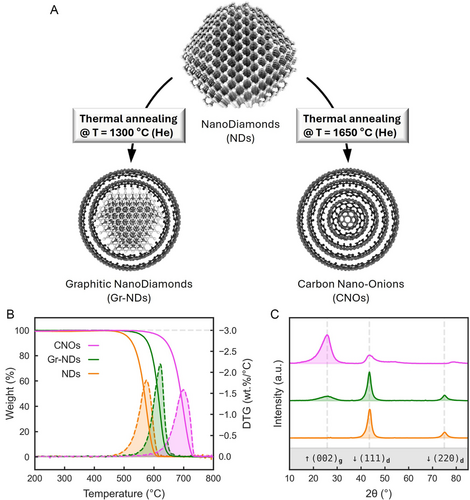
Previous studies showed that graphene flakes (GFs) and NDs can achieve ultralow friction on rough DLC coatings, though only in dry conditions due to the formation of a nanoscroll-based TL.[28] To address these limitations in humid conditions and to disentangle the respective contributions of graphitic layers and diamond cores in DLC-steel contacts, we investigated the tribological behavior of carbon nano-onions (CNOs) and a newly developed nanostructure, Gr-NDs. We synthesized both nanomaterials by a thermal annealing process by using the same NDs precursor. At high temperature, a rearrangement of the carbon atoms of NDs takes place with sp3 to sp2 phase transformation from the outside to the inside. Graphitization begins at the diamond (111) planes, proceeding from the NDs surface to the core.[29] At 1300 °C, Gr-NDs are produced, which feature a few sp2 graphitic layers around the sp3 diamond core (Figure 1A, left). At a higher temperature of 1650 °C, the graphitization is complete, and CNOs are produced, which consist of sp2 graphitic multilayers (Figure 1A, right).[30] The successful formation of the two carbon nanomaterials (CNMs) was corroborated by different characterization techniques, namely thermogravimetric analysis (TGA), X-ray diffraction (XRD), and high-resolution TEM (HRTEM). Figure 1B displays the TGA and derivative thermogravimetric (DTG) profiles of NDs, Gr-NDs, and CNOs under an oxidative atmosphere. The DTG peaks indicate that thermal decomposition occurs at progressively higher temperatures as the degree of graphitization increases. Specifically, NDs, Gr-NDs, and CNOs show decomposition maxima at 575, 623, and 700 °C, respectively, reflecting increased thermal stability with structural transition from sp3-rich ND to ordered sp2 carbon. Figure 1C shows the XRD spectra of the three CNMs, highlighting their structural progression with increasing annealing temperature. NDs exhibit sharp diamond (111)d and (220)d reflections, which disappear in CNOs. In contrast, the (002)g graphitic peak emerges in Gr-NDs and becomes dominant in CNOs. The CNO spectrum also reveals additional characteristic graphitic reflections, including the (100 + 101)g peak at ≈44°, the (004)g peak at ≈54°, and the (110)g peak at ≈78°.
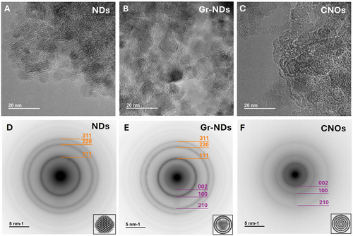
Representative HRTEM images of NDs, Gr-NDs, and CNOs, along with their corresponding electron diffraction (ED) patterns, are presented in Figure 2. NDs (Figure 2A and D) present the characteristic (111), (220), and (311) diamond planes (indicated in orange in the EDs). Gr-NDs still show reflections from the ND cores (Figure 2B and E) together with the (002) graphitic planes (2–5 shells) visible in the images, and confirmed by the rings in EDs (indicated in purple). Finally, in CNOs (Figure 2C and F) only the signatures of graphitic shells are visible, which is in agreement with XRD results.
Following their characterization, CNMs have been systematically deposited on DLC substrates, as described in the experimental section. The functionalized DLC substrates were mounted on a ball-on-disc tribometer and tested against a steel ball under a 1 N normal load, as depicted in Figure 3A. Figure 3B and C summarize the results obtained in humid air and dry nitrogen, respectively. The black curves represent the tribological behavior of pristine DLC and serve as a reference. The orange curves illustrate the combined effect of GFs and detonated NDs, which, as previously discussed, exhibit ultralow friction only in dry conditions. The pink and green curves correspond to DLC functionalized with CNOs and Gr-NDs, respectively. Functionalization with CNOs led to a modest improvement in the tribological performance of the industrial DLC, in both humid (RH 50%–60%) and dry (RH 15%) environments, as indicated by the similar evolution of the CoF over time. In both cases, the CoF stabilized at ≈0.1, demonstrating enhanced performance but remaining above the ultralow friction threshold (CoF < 0.1). Notably, functionalization with Gr-NDs enabled the achievement of ultralow friction not only in dry nitrogen but also in a humid air environment. As shown by the green curves in Figure 2B and C, the CoF in dry nitrogen decreased to ≈0.07 while in humid conditions stabilized around 0.09, highlighting the superior humidity-resistant tribological performance of Gr-NDs.
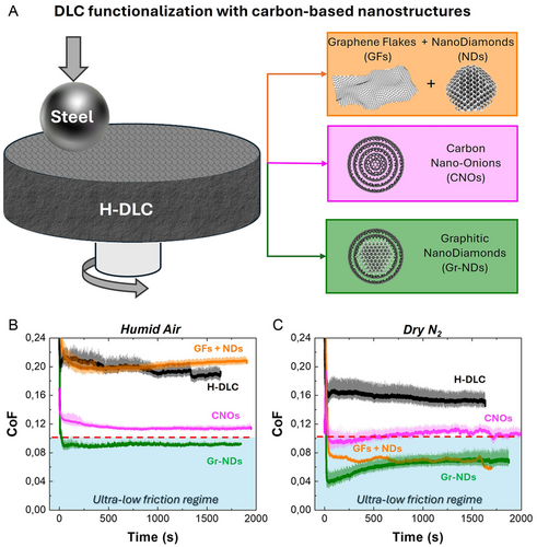
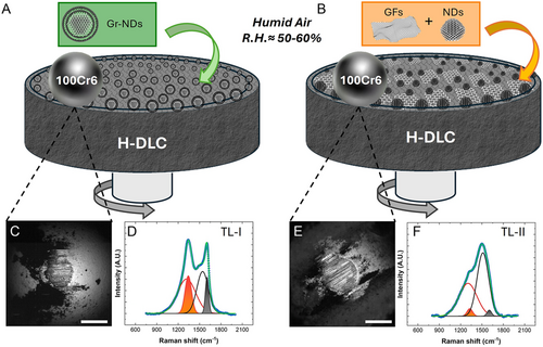
The remarkable friction reduction obtained with Gr-NDs in a humid atmosphere on the micro-rough DLC coating represents a major breakthrough, as it demonstrates exceptional performance under the most common and challenging real-world operating conditions, making it highly relevant for industrial applications. For this reason, our attention has been focused on the tribological response in the presence of humidity, with particular emphasis on comparing extreme cases, namely the ones resulting from Gr-NDs and GFs + NDs functionalization, respectively, as shown in the scheme diagram of Figure 4A and B. A further indication of the effectiveness of Gr-NDs functionalization comes from the wear analysis conducted at the end of the tribological tests on both the DLC coating and the steel counterpart. While the traces left on the coating are barely perceptible and are only identified by the accumulation of debris at the edges (see Figure S1, Supporting Information), the optical images on the counterpart reveal a circular contact region typical of ball-on-flat geometry (Figure 4C and E). The removed wear volume, calculated as a spherical cup, results in 0.57 10−4 and 2.6 10−4 mm3 using Gr-NDs and GFs + NDs functionalization, respectively. This indicates that the wear rate is also drastically reduced through the use of Gr-NDs. A systematic Raman analysis was carried out to get insight into the nature of the nanostructures constituting the TLs formed by sliding in humid air. In the following, the TL formed by sliding on DLC functionalized with Gr-NDs in a single-step deposition (I) will be denoted “TL-I”, while that formed by sliding on DLC functionalized with the double-step procedure (II) - GFs followed by NDs - will be denoted “TL-II”.
As a reference, we first measured the Raman spectrum of pristine Gr-NDs deposited from an alcohol solution on a silicon substrate (see Figure S2, Supporting Information). The characteristic features related to G and D bands are clearly visible respectively around 1340 and 1590 cm−1, thus reflecting the presence of multilayer graphitic shells wrapping ND core. Nevertheless, a careful peak analysis revealed the need for four different contributions to best fit experimental data. We introduced two broad G and D components most probably related to the accumulation of carbon residues from the deposition procedure, plus two other narrow contributions at around 1333 and 1593 cm−1. In line with recent literature, the latter respectively indicate the contribution due to NDs cores and the presence of graphitic layers and/or functional groups on the NDs surface.[31-35]
Raman analysis on TL-I (Figure 4D) shows very similar features compared to pristine Gr-NDs, confirming the presence of the core–shell arranged nanostructures embedded in the TL-I. On the contrary, the TL-II gives rise to very different Raman features (Figure 4F): in particular, the two broad components related to the amorphous carbon (a-C) accumulation are predominant while the other two narrow ones are almost completely knocked down, confirming that the core–shell NPs were not produced during the sliding. Moreover, the intensity ratio of D and G broad peaks is higher on TL-I (ID/IG = 0.8) with respect to TL-II (ID/IG = 0.5). These results clearly indicate that in humid air, the use of Gr-NDs results in the formation of a TL rich in core–shell structures, and it is a first indication of a larger presence of sp2 graphitic domains in TL-I.
To elucidate the role of the core–shell arrangement in humid conditions and for disentangling the contribution of the nanostructures within the TLs, a complete TEM analysis was performed. The TEM lamellae were extracted from the steel counterface by FIB milling following the preparation method depicted in Figure 5 and described in paragraph 2.6.
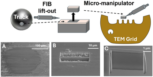
Figure 6 shows HRTEM characterization of both TL-I and TL-II. Panel A presents a portion of the lamella extracted from TL-I, showing a thickness of 85 nm (see Figure S3, Supporting Information). Panel B is a zoom inside TL-I highlighting the presence of diamond-structured nuclei and, in some areas, even the graphitic planes. Panels C and D refer to a portion of lamella from TL-II. Here, TL thickness varies from 45 up to 80 nm. These variations might reflect the intrinsic nonuniformity of the TLs within the contact area. However, analysis of extended low-magnification images of the lamellae (see Figure S3, Supporting Information), indicate that the thickness of the TL-I is more uniform than that of the TL-II, possibly reflecting the different influence of the steel surface erosion phenomena in the two systems. The diamond-structured nuclei are still visible, while graphitic planes are more challenging to identify.

The elemental composition of the TLs was obtained by EELS performed in STEM from rectangular regions inside the layers. The extended EELS spectra in the range 240–750 eV (see Figure S4, Supporting Information) show traces of iron and chromium which reasonably result from the steel counterpart erosion in addition to the carbon and oxygen main structures. To get insight into the carbon nanostructures’ configuration that compose the TLs, a detailed EELS analysis was performed on the C-K edge (Figure 7). The representative spectra for TL-I and TL-II were obtained by averaging the EELS signal from an area ≈50 nm by 50 nm wide. The information extracted from this analysis relates to the excited state electronic structure, bonding, and the orbital hybridization of the specimen, thus providing concrete help in deciphering the different degree of sp2 and sp3 carbon-based orbitals within the TLs. The carbon sp2 content can be quantified from the ratio of the integrated intensity of the π* peak at 285 eV with respect to the whole spectrum. The sp2 fraction was calculated according to,[36] and is quantified as follows for three reference samples and the two TLs (Figure 7A): 100% for CNOs, 46% for Gr-NDs, 35% for NDs, 49% for TL-I, and 65% for TL-II. We have used an asymmetric shape for the π* peak, and the ratio was calculated in the integrated range 282–305 eV, to avoid the effect of multiple scattering at higher energy, which cannot be completely removed by deconvolution with a low-loss spectrum. We used the C-K spectrum from CNOs as a reference for 100% sp2, because of the very close result compared to crystalline graphite (within the error of the fitting procedure). Moreover, since the particles are oriented in all directions, there is no need to use magic angle conditions for EELS acquisition.[37] An error of 4% has to be considered in these estimations.
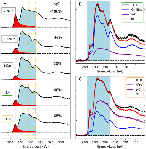
The fine structures of the C-K edge were also exploited to distinguish the different carbon allotropes within the two TLs of interest and are reported in Figure 7B and C. Assuming that NPs utilized for functionalization are present in the TL as indicated by Raman analysis, EELS signals from both pristine Gr-NDs and NDs were used as references together with a reference for amorphous carbon (a-C) taken from the holey support film of the TEM grid (see Figure S5, Supporting Information). Figure 7B and C show the results of the fit of the pristine NPs references and the a-C reference to the TLs. The two TLs are well described by the presence of an amorphous network plus a contribution corresponding to Gr-NDs on TL-I and a contribution from NDs on TL-II. The amorphous network is more evident in the case of TL-II. Regarding the π* peak region at 285 eV, a single peak is clearly visible in the case of TL-II, whereas in the case of TL-I, new features appears between the π* peak—still visible as the first step in the spectra at 285 eV—and the rise of σ* states, marked by the second step at 290 eV. In agreement with recent literature, these features can be attributed to the bonding of various oxygen-containing functional groups. Indeed, within the energy range of 285 to 289 eV, different energy-loss near edge structure (ELNES) features have been identified and assigned in order of increasing energy to specific oxygen functional groups, such as COH in hydroxyl groups, CO in epoxides and ether groups, CO in carbonyl groups, and OCOH in carboxyl groups.[38-44] Therefore, the O-K edge was analyzed in detail, and interestingly, new features were also identified in TL-I within the energy range of 530 to 540 eV. These features are typically attributed to the same functional groups identified in the C-K edge, namely OC carbonyl groups at 533.6 eV, COC bonds in epoxy groups at 534.9 eV, COC bonds in ether groups at 536.2 eV, and OH bonds in hydroxyl groups at 538.5 eV.[38-44] The spectra shown in Figure 8A-D confirm the increase in oxygen functional groups in TL-I compared to TL-II, particularly the presence of COC (epoxy and ether) groups. Furthermore, the analysis of extended EELS spectra (see Figure S4, Supporting Information) enables the evaluation of the O/C fraction in both TLs, measured at 0.22 ± 0.04 for TL-I and 0.10 ± 0.02 for TL-II. In these estimations, we have excluded the oxygen fraction arising from a possible oxidation of Fe and Cr due to the very low presence of these metallic species compared to the carbon component.
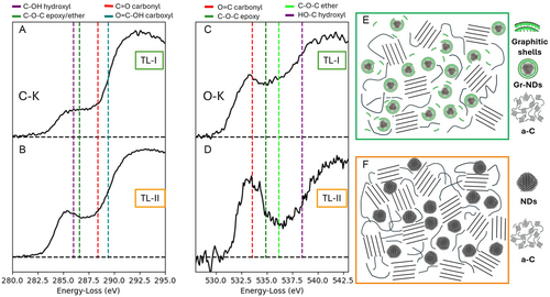
The presence of oxygen in the contact region was further verified by SEM–EDS measurements, as reported in detail in Figures S6 and S7,Supporting Information. The Fe signal was distributed uniformly over the beads’ surface, being masked only by some thick carbon debris particles outside the contact area. Indeed, the carbon signal was also visible within the contact region and highlighted the formation of the TLs. Interestingly, the oxygen signal was particularly localized in the contact area, being superimposed to the C signal from the TLs. No oxygen signal was found in correspondence to the thick carbon debris, which indicates that oxygen-containing functional groups mostly formed under the action of contact pressure and sliding friction, and they ultimately localized on the TLs. A schematic representation of the structures directly involved in the mechanism responsible for reducing friction is shown in Figure 8E and F for TL-I and TL-II, respectively.
3 Discussion
The tribological results presented here demonstrate the overall effectiveness of the single-step functionalization by Gr-NDs (Table 1 and 2). Their use significantly enhances the performance of the industrial DLC coating under both humid (RH 50%–60%) and dry (RH 15%) environments.
| Sliding Interface | Functionalization | Environment | Roughness | CoF | Ref. |
|---|---|---|---|---|---|
| Si-DLC | GFs + NDs | Dry N2 | 0.02 μm | 0.004 | [22] |
| Si-DLC | MoS2 + NDs | Dry N2 | 0.02 μm | 0.005 | [23] |
| Si-DLC | GFs + FeNP | Dry N2 | 0.02 μm | 0.009 | [24] |
| Si/DLC-Steel | GFs + NDs | RH 10% | 0.02 μm | 0.024 | [16] |
| Si/DLC-Steel | h-BN + NDs | Dry N2 | 0.0015 | [26] | |
| Si/DLC-Steel | h-BN + NDs | Dry N2 | 0.001 | [27] | |
| Industrial DLC-Steel | GFs + NDs |
Dry N2 (RH 15%) |
0.5 μm | 0.07 | [28] |
| Industrial DLC-Steel | Gr-NDs |
Dry N2 (RH 15%) |
0.5 μm | 0.07 | This study |
Unlike functionalization with the physical mixture of GFs and NDs (GFs + NDs), which requires dry conditions to effectively form the nanoscroll-type structures, the preformed core–shell structure of Gr-NDs ensures ultralow friction even for a relevant value of RH. This behavior depends on the peculiar characteristics of the TL that forms in the contact area. In fact, it is now widely recognized that the tribological performances of a metal-DLC sliding contact are dictated by the TL forming on the metal counterpart.[45-50] For this reason, a comprehensive analysis of the two TLs formed in humid air—namely that resulting from Gr-NDs functionalization (TL-I) and that involving GFs + NDs functionalization (TL-II)—has been presented. The HRTEM images clearly reveal diamond-type nuclei embedded in both the TLs. However, traces of graphitic planes have been identified exclusively in TL-I (Figure 6B, green lines). Directly resolving the graphitic planes of core–shell NPs presents a significant challenge due to the combined effects of TEM lamella thickness relative to particle size and the random orientation of NPs within the lamella. In fact, initial experimental studies identified these structures in the wear debris rather than in the TL itself.[22, 51, 52] More recent papers presented HRTEM images in which planes of 2D structures are identified in the lamella, though they typically appear as tiny traces within an amorphous matrix.[16, 25, 26] To overcome these difficulties, we combined HRTEM images with Raman analysis. The Raman analysis shown in Figure 4D and F strongly confirms the presence of Gr-NDs within TL-I, as the spectra retained the original specific features of the Gr-NDs core–shell structure. In contrast, Raman spectra from TL-II, which did not contribute to friction reduction as effectively, exhibited a more amorphous carbon-like structure. This evidence confirms that NPs with core–shell morphology are embedded in TL-I and pivotal to achieving ultralow friction conditions in metal–DLC contacts. Moreover, the Gr-NDs used in this work for the first time prove to be an excellent solution across a wide range of environmental and contact conditions. Similar nanostructures obtained by mixing GFs and NDs in solution[16] have proven effective only on ultraflat model surfaces, in low humidity environments (RH = 10%), and for contact pressures 2 or 3 times lower than those used in our experiments. The distinctive characteristics of TL-I and TL-II have been further explored by a detailed TEM–EELS analysis. A comparison of the π* peak on the C-K edge quantifies the relative sp2 content, which is higher in TL-II (65%) compared to TL-I (49%) (Figure 7A). However, it is important to emphasize that the sp2 relative content includes contributions from both graphitic shells and a-C. By extending the fitting procedure to the entire line shape, the amorphous fraction has also been assessed (Figure 7B and C). Although not fully quantitative, this approach suggests that TL-II contains a significantly larger amorphous component than TL-I. Therefore, we conclude that the sp2 component in TL-I is still largely attributed to the presence of graphitic shells. This finding highlights that the superior friction reduction performance is not solely related to the sp2 content, but also to its structural quality. Specifically, the presence of graphitic shells appears to be a key factor in achieving ultralow friction conditions,[53] whereas the sp2 component in amorphous carbon does not provide the same lubricating effect. This is in agreement with current models[4, 5, 54] that actually explain the self-lubricating effect of DLC coatings with the formation of a graphitic-type TL on the counterpart (in particular on a metallic counterbody). It follows that this effect should be naturally emphasized by functionalization with CNOs, i.e, NPs with a complete sp2 character. On the contrary, our tribological results (Figure 3B and C) indicate that NPs with a reduced sp2 content (≈49%), in the form of closed shells wrapped around diamond-type cores, give better results both in humid air and dry N2. Berman et al.[23] already observed that the DLC–steel contact functionalized by “stiff” CNOs, i.e., onion-like structures of 15–20 graphitic layers formed in operando via tribochemical reactions, performed better than with “soft” CNOs (i.e., onion-like structures with 5–7 layers thick walls). In other words, in order to obtain ultralow friction, carbon-based lubricating nanoscrolls must possess two concurrent features. On one hand, sufficient hardness to withstand the high contact pressure and, on the other hand, a relatively soft structure exposed to contact with self-lubricating characteristics. These are essentially two main characteristics displayed by the Gr-NDs nanostructures used in this work. Finally, the detailed EELS analysis of both the carbon and oxygen K-edge spectra (Figure 8) provides deeper insight into the tribochemical processes influencing TL formation and stability. In particular, the carbon K-edge analysis of TL-I (Figure 8A) reveals an alteration in the π* peak shape compared to the original Gr-NDs (Figure 8B), characterized by a reduction in intensity and a slight shift toward higher energies. This alteration is not observed in TL-II (Figure 8B) and can reasonably be attributed to oxidative processes affecting the graphitic shells, specifically the formation of oxygen-containing functional groups such as COH (hydroxyl) and COC (epoxy and ether) groups, appearing at 286.0 eV and 286.6 eV, respectively. This assumption is further supported by the analysis of the oxygen K-edge (Figure 8C), which reveals the emergence of new contributions in TL-I, compared to TL-II, at 534.9 and 536.2 eV, indicative of the presence of COC (epoxy and ether) groups.[38-44] These observations suggest that the tribolayer generated by Gr-NDs exhibits localized graphitic domains that are chemically active under tribological stress. These regions undergo selective oxidation, leading to the formation of oxygen-containing groups that support water-mediated lubrication. The ability of Gr-NDs to maintain ultralow friction in humid air can be attributed to the unique chemical and structural characteristics of their graphitic shell. The presence of oxygen-containing groups (e.g., COC and COH), as confirmed by EELS, promotes the adsorption of water molecules via hydrogen bonding. This leads to the formation of a stable, hydrated boundary layer that facilitates lubrication. Unlike amorphous carbon films, the graphitic shell of Gr-NDs remains structurally ordered and does not degrade in the presence of moisture, enabling a robust TL even at moderate RH (50%–60%). In contrast, TL-II shows a lower oxygen content, with a prevalence of CO (carbonyl) groups, suggesting that oxidation primarily affects the amorphous carbon regions in the absence of pre-existing graphitic shells. These differences are visually summarized in the schematic representations in Figure 8E and F, where TL-I is depicted as a structured network of Gr-NDs and graphitic shells, while TL-II consists mainly of amorphous carbon and dispersed NDs. This comparison reinforces the idea that both the structural integrity of the core–shell NPs and their tribochemical evolution play a crucial role in achieving ultralow friction. The formation of these oxygen-containing functional groups may enhance lubrication by modifying interfacial interactions and improving tribochemical stability. For instance, in partially hydrogenated DLC (H content 18%) a lower CoF was measured in an oxidizing atmosphere (air or oxygen) with respect to that measured in dry atmosphere.[55] Moreover, oxygen-containing functional groups can improve compatibility with humid environments by promoting interfacial water lubrication effects.[44, 56-58] Under steady state conditions, oxygen-rich, hydrophilic carbonaceous TLs may in fact help to stabilize along the sliding interface a network of physisorbed water molecules supplied from the gas phase. These in turn may act as a molecular boundary lubrication film. Lubrication by physisorbed water was suggested to effectively operate up to 1 GPa contact pressure for both graphitic and DLC-based TLs,[57, 58] in fact providing a slightly higher COF (≈0.10–0.15) than that measured for the Gr-NDs case (≈0.09, Figure 2B).
4 Conclusion
This study demonstrates that functionalizing industrial, micrometer rough DLC coatings with Gr-NDs enables ultralow friction (CoF < 0.1) and a significant reduction in wear losses in both humid (RH 50%–60%) and dry (RH 15%) environments. Unlike previous methods relying on in situ nanoscroll formation, Gr-NDs provide a stable core–shell structure that enhances tribological performance without requiring controlled conditions. The formation of graphitic structures exclusively within TL-I (i.e., TL resulting from Gr-NDs functionalization) is the key factor in achieving a substantial reduction in the CoF. The presence of well-organized sp2 domains in the TL, as confirmed by Raman and HRTEM analysis, enables the formation of a lubricating interface that remains effective even under standard humidity conditions. This structural feature, absent in TL-II (involving GFs + NDs functionalization), highlights the critical role of preformed graphitic shells in stabilizing the tribological response of DLC coatings. Furthermore, the detailed EELS analysis underscores the influence of oxidation and the water layer in enhancing lubrication. The presence of oxygen-containing functional groups, particularly COC and COH, in TL-I suggests a tribochemical evolution of the graphitic shells, promoting a hydrophilic interface capable of retaining a molecular water layer. This hydration-assisted mechanism provides an additional lubrication pathway, preventing adhesion and wear, and explaining the superior performance of Gr-NDs compared to conventional functionalization approaches. The proposed approach offers a scalable and environmentally friendly solution for reducing friction and wear in DLC coatings, and in particular, it allows to overcome the operating limit of partially hydrogenated DLC films in humid environments. Its simplicity and effectiveness make it particularly attractive for industrial applications, including automotive components, aerospace systems, and mechanical devices. Possible future developments include optimizing the Gr-ND synthesis process or integrating other nanomaterials to further improve performance. Nevertheless, testing and validation of this approach under high humidity (≥70% RH) remains the main challenge. In this regime the tribological behavior of carbon-based systems is still an open and complex problem because additional interfacial mechanisms—such as capillary condensation, galvanic corrosion, and humidity-driven tribochemistry of carbon species—may significantly affect TL stability and interfacial shear dynamics.
5 Experimental Section
DLC Substrates
The DLC coatings were deposited on a disc-shaped metal substrate (diameter 45 mm) via industrial processes (STS Group, Italy) according to a specific multilayer architecture developed to optimize tribological properties and resistance to corrosion. Briefly, the samples were composed of aluminum alloy (AlSi10Mg) metallic disks and different functional layers grown between metallic substrate and the final DLC film, respectively: 25 μm thickness of electroless nickel phosphorus plating, and a 2 μm thickness of chromium-based buffer layer. The DLC coating, deposited through PA-CVD at a temperature of 250 °C, resulted in a hydrogenated amorphous carbon coating (a-C:H%≃23) with a typical thickness of 2.5 μm and hardness of 2600 Hv according to the manufacturer specifications. The surface morphology was investigated by atomic force microscopy (AFM) (see Figure S8, Supporting Information). The surface roughness was Sq = 0.50 ± 0.05 μm according to the procedure previously developed by the authors.[28, 59, 60]
CNMs and Deposition Techniques
NDs: Pristine NDs with an average particle size of 4–6 nm were purchased from Carbodeon Ltd. and used as received. Gr-NDs: Gr-NDs were synthesized by thermal annealing of pristine NDs using a similar procedure to that of CNOs. Briefly, 400 mg of NDs were placed in a graphitic crucible and annealed under helium, with the final temperature set to 1300 °C and held for 60 min. The process yielded ≈350 mg of Gr-NDs. CNOs: Pristine CNOs, measuring 6–7 nm in diameter with 6–8 concentric shells, were synthesized by thermally annealing of NDs, following a previously reported procedure[61] and a patented protocol (Figure 1A, right).[62] Briefly, 1.1 g of NDs were placed in a graphitic crucible and annealed in a GSL-1750X-S60 tube furnace under a helium atmosphere. The process involved successive heating ramps until 1650 °C, a 60-minute dwell at the final temperature, and controlled cooling to RT. This yielded ≈750 mg of pristine CNOs. All the carbon nanostructures were stored in isopropanol suspension; just before the deposition they were sonicated for 45 min to break up relatively large agglomerates naturally formed in the stationery suspension. In detail, a small volume (70 μL) of the carbon nanostructures’ suspension (1 mg mL−1) was consecutively deposited on the substrates of interest for a total volume of ≈0.42 mL resulting in 0.420 mg of carbon nanostructures per 15 cm2. The samples were then dried under nitrogen flow to ensure complete solvent removal. GFs: GFs were purchased by Graphene Laboratories Inc. (Calverton NY) as a colloidal alcohol solution with a final concentration of 1 mg L−1. The colloidal solution contains mainly single-layer GFs with an estimated size between 0.5 and 2 μm, suspended in ethanol. The deposition over the DLC coating was performed by the drop-casting technique: in detail, a small volume (70 μL) of the colloidal solution was consecutively deposited on the DLC substrate, for a total volume of ≈1 mL, promoting the ethyl alcohol evaporation after each drop deposition under a gentle nitrogen flow.
Material Characterizations: TGA
TGA measurements were conducted with a TA Q500 analyzer, using a platinum pan sample holder. After equilibrating the sample at 100 °C for 20 min, measurements were carried out under air flow (20 mL min−1) at a 10 °C min−1 heating rate up to 800 °C. XRD: XRD measurements were performed with a PANalytical Empyrean instrument (Cu Kα radiation source) using a zero-diffraction Si substrate. HighScore 4.5 dedicated software was used for data analysis. HRTEM: TEM images taken with a parallel beam (HRTEM), annular dark-field scanning TEM (ADF-STEM) together with spatially resolved EELS were performed on a ThermoFisher Scientific Talos 200S microscope, operated at 200 kV and equipped with a postcolumn spectrometer (Gatan Inc.).
Tribological Characterizations: Ball-on-Disc Tribometer
Tribological tests were carried out using a CSM ball-on-disk tribometer. The instrument consisted of a rotatable sample holder, where the sample disk was secured, and an upper arm that applied an external load through a dead mass. A 100Cr6 steel sphere with a 4 mm diameter was used as the counterpart, simulating a typical industrial tribological contact between DLC and stainless steel. The system operated within a sealed chamber equipped with a venting orifice and a gas line, allowing a constant nitrogen (N2) flow. The tests were performed at a fixed linear velocity of 10 cm s−1 for 1800 s, which corresponded to about 180 m of sliding distance. The duration of the tribological tests was set to capture the full transition from run-in to steady-state friction and assess the stability of the TL formation. Multiple tests were conducted on the same sample by varying the contact position on the disk (track radius). The applied load was set to 1 N, generating a maximum Hertzian contact pressure of ≈0.8 GPa. Due to the pronounced surface roughness of the DLC coating, the actual contact pressure was expected to be at least an order of magnitude higher (see Supplementary Information, Contact pressure at the steel-DLC contact). This elevated pressure exceeds the elastic limit, ultimately leading to the significant surface wear of the steel balls. Before applying the test load, a counterweight system ensured a zero-load condition, and this zeroing procedure was repeated for each measurement. The chamber included a thermometer and a hygrometer to monitor environmental conditions during testing. Each test was conducted under two different sliding conditions: standard humidity conditions, referring to ambient air with a relative humidity (RH) of 50%–60%, and dry N2, characterized by a RH of 15% and reduced atmospheric oxygen. The latter condition was achieved by introducing high-purity N2 into the chamber. Throughout all tribological tests, experimental parameters were maintained constant to ensure reproducible and comparable results. Wear analysis: The wear scars on the steel balls were analyzed based on the removed volume, calculated using top-view optical microscopy images (Olympus BX51M, 10× magnification). The wear scars were approximated as circular areas with an area A = π r2, and the worn volume was modeled as a spherical cap with base A and height h. The cap height h was determined using the relation: h = R−(R2−r2)1/2 and V ball = π h2 (R− h/r) where R = 2 mm and r = (A/π) ½. Raman Spectroscopy: Raman spectra were acquired using a LabRAM HR Evolution (Horiba) operating at a wavelength of 532 nm. To prevent surface damage, the laser power was carefully adjusted between 1 and 5 mW. Measurements were performed using a 100× magnification objective and a 600 g mm−1 diffraction grating. These precautions ensured that no visible surface damage or spectral shape alterations occurred during the measurements. Spectra were recorded in the range of 500–3500 cm−1. Focused Ion Beam (FIB) lamella preparation: To investigate the contact region of the steel counterpart by TEM, we prepared cross-sectional views of the samples (ultrathin lamellae) with FIB milling, performed on a Dual Beam FIB-SEM system (FEI DB Strata 235M) using the lift-out technique. At the center of the 100Cr6 steel sphere, a protective Pt–C strip was first deposited by the electron beam to prevent any ion damage to the surface, followed by ion beam deposition to thicken the layer. A slab of material, ≈5 μm deep, was obtained below the Pt–C strip by milling two opposite trenches, and the slab was FIB cut at the bottom and on one side. The tip of a micromanipulator was brought into contact with the side, where it was attached by Pt–C FIB deposition. The other side was cut free, and the slab was lifted out by the micromanipulator and transferred to the half TEM grid, where it was attached by the same deposition. The end of the slab was finally thinned down to about 50 nm with low milling current (100 pA, 30 kV), followed by a polishing step at low energy (5 kV), to become an ultrathin lamella ready for TEM analysis. A schematic diagram of all the steps required for the preparation of the lamellas is shown in Figure 5. EELS: Spatially resolved EELS spectra were acquired on the carbon (C–K) and oxygen (O–K) ionization edges using the postcolumn spectrometer (Gatan Inc.) with 0.1 eV energy dispersion. The reference spectra were measured integrating an area of the sample with a selective area aperture of 10 μm diameter acquired in a hole in the C-holey support film of the TEM grid, to assure measuring only the carbon signal from the reference samples. The TLs were measured by integrating an area of ≈50 × 50 nm in STEM mode. The thicknesses of the lifted-out FIB cross sections were verified to be ≈68 ± 13 nm for the TL-I sample and 55 ± 11 nm for the TL-II sample, respectively, measured with the log-ratio method from low-loss spectra.[63] Scanning Electron Microscopy (SEM) and Energy-Dispersive Spectroscopy (EDS): EDS characterization of contact regions on the steel counterpart was performed by the SEM Nova NanoSEM 450 (FEI Company), equipped with the EDS Bruker QUANTAX-200. SEM images were acquired at 12 KV.
Acknowledgements
A.M and G.P acknowledge ECOSISTER project funded under the National Recovery and Resilience Plan (NRRP), Mission 04 Component 2 Investment 1.5–NextGenerationEU, Call for tender n. 3277 Award Number: 0001052. G.B. thanks the Italian Ministry of University and Research Decree 128-21/06/2022, contract no. IR0000027 ‘Infrastructure for Energy Transition and Circular Economy-iENTRANCE@ENL’. S.G. acknowledges Research Ireland for funding (22/FFP-A/11067) and the School of Chemical Sciences at DCU (postdoctoral fellowship to A.C.). The authors like to thank Centro Interdipartimentale Grandi Strumenti, Università di Modena e Reggio Emilia (CIGS-UNIMORE) for access and support in using advanced instrumentation for materials characterization.
Conflict of Interest
The authors declare no conflict of interest.
Author Contributions
Andrea Mescola: conceptualization (equal); data curation (equal); writing—original draft (equal); writing—review & editing (equal); Giovanni Bertoni: data curation (equal); investigation (equal); writing—original draft (equal); writing—review & editing (equal); Gian Carlo Gazzadi: investigation (equal). Michał Bartkowski: investigation (supporting); visualization (supporting). Adalberto Camisasca: investigation (supporting). Silvia Giordani: data curation (equal); writing—original draft (equal); writing—review & editing (equal). Renato Buzio: data curation (equal); writing—original draft (lead); writing—review & editing (lead). Guido Paolicelli: conceptualization (lead); data curation (equal); funding acquisition (lead); investigation (equal); writing—original draft (lead); writing—review & editing (lead). Andrea Mescola and Giovanni Bertoni contributed equally to this work.
Open Research
Data Availability Statement
The data that support the findings of this study are available from the corresponding author upon reasonable request.


