Ultrasound Manipulation and Extrusion of Active Nanorods
Abstract
Synthetic self-propelled nano and microparticles have a growing appeal for targeted drug delivery, collective functionality, and manipulation at the nanoscale. However, it is challenging to control their positions and orientations under confinement, e.g., in microchannels, nozzles, and microcapillaries. This study reports on the synergistic effect of acoustic and flow-induced focusing in microfluidic nozzles. In a microchannel with a nozzle, the balance between the acoustophoretic forces and the fluid drag due to streaming flows generated by the acoustic field controls the microparticle's dynamics. This study manipulates the positions and orientations of dispersed particles and dense clusters inside the channel at a fixed frequency by tuning the acoustic intensity. The main findings are: first, this study successfully manipulates the positions and orientations of individual particles and dense clusters inside the channel at a fixed frequency by tuning the acoustic intensity. Second, when an external flow is applied, the acoustic field separates and selectively extrudes shape-anisotropic passive particles and self-propelled active nanorods. Finally, the observed phenomena are explained by multiphysics finite-element modeling. The results shed light on the control and extrusion of active particles in confined geometries and enable applications for acoustic cargo (e.g., drug) delivery, particle injection, and additive manufacturing via printed self-propelled active particles.
1 Introduction
Applications of synthetic active matter, including collections of interacting self-propelled microparticles, are rapidly growing.[1, 2] Some examples include novel treatments for diseases[3, 4] and 3D printing.[5, 6] Many practical realizations of synthetic active matter rely on the effective extrusion and deposition of self-propelled particles from liquid media in the desired location. This task is nontrivial due to the active nature of these particles, which behave differently than standard passive ones: they exhibit rheotaxis (migration against the applied flow),[7-10] self-assembly,[11-13] and the onset of collective behavior.[9, 14-16] Hydrodynamic focusing is the most common technique to concentrate and extrude passive particles. It is usually performed by attaching a nozzle to the channel.[17] But the ability of active particles to cross streamlines and swim against the flow significantly hinders the focusing effect of a nozzle.[8]
Bi-metallic gold-platinum (Au-Pt) nanorods are one of the most studied examples of synthetic active particles.[18-20] The rods exhibit self-propelled directed motion in hydrogen peroxide (H2O2) solution. The same nanorods display directed motion in a uniform field created by surface acoustic wave transducers.[21, 22] Namely, due to the density difference between gold and platinum, the rod's center of mass is displaced from the geometrical center making it acoustically active, so-called self-acoustophoresis.[23, 24] Thus, gold-platinum nanorods exemplify an “omnivorous” active matter realization powered by multiple energy sources. Another realization of the acoustophoretic propulsion relies on excitation of microbubbles inside a cigar-shaped hollow particle.[25]
Ultrasound is routinely used to focus and separate spherical beads, cells, or particles with different properties, e.g., density or shape.[11, 26-35] The studies are primarily conducted in a parallel channel geometry. However, little is known about how strongly anisotropic particles (e.g., nanorods) behave in microfluidic channels of complex shapes, e.g., nozzles. While several studies have been performed exploring how different particle shapes affect movement,[21, 23, 36-38] there has been no focus on different channel geometries. Understanding transport in microfluidic channels with a converging nozzle is essential as the flow rate increases with the width decrease.[8, 17, 39, 40]
Here we study the synergistic effect of acoustic and hydrodynamic focusing to control, extrude, and separate active nanorods under the nozzle confinement. Our approach extends the acoustic and hydrodynamic focusing techniques for passive particles.[41-43] The main results are summarized as following: i) We discovered the synergistic effect of acoustic and hydrodynamic focusing to control, extrude, and separate active nanorods under nozzle confinement. Our approach extends the acoustic and hydrodynamic focusing techniques for passive particles; ii) We implemented the control of the positions and orientations of dispersed particles and dense particle assemblies inside the channel. The control is provided by the frequency and intensity of the acoustic field; iii) We implemented the acoustic control that enables selective containment, extrusion, and manipulation of active nanorods by suppressing detrimental rheotaxis; iv) We obtained insights into the flow and acoustic field distributions through the COMSOL multiphysics finite-element modeling.
Besides a fundamental understanding of the dynamics of active matter under confinement, our results hint at possible applications in acoustic cargo (e.g., drug) delivery, active particle injection, and even direct-ink-writing 3D printing by self-propelled active particles (printing with “active ink”: suspension of active participles in a polymer solution).
2 Results and Discussion
Experiments were performed in a polydimethylsiloxane (PDMS) microfluidic channel on top of a 51 mm silicon wafer with a piezoelectric transducer attached below with epoxy adhesive (Figures 1a,b). The channel's total length is 14.5 mm, and it is composed of three sections: an inlet channel with parallel horizontal walls separated at a distance of 270 µm, a tapered nozzle with a length of 300 µm, and a parallel outlet channel with walls at a distance of 25 µm. The height of the channel is fixed at 100 µm. Schematics with dimensions of the microfluidic channel are shown in Figure 1c. The signal to the piezoelectric transducer was provided by a wave function generator and later amplified. See Figure S1 (Supporting Information) for the photo of the experimental setup.
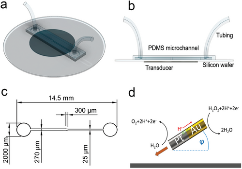
The particles are rod-shaped cylinders with gold and platinum halves longitudinally opposed, approximately L = 2 ± 0.5µm long and a = 150 ± 50 nm in radius. (See Figure S2, Supporting Information for a typical scanning electron microscopy (SEM) image of the Au-Pt nanorods). These particles become “active” when added to a solution of hydrogen peroxide (H2O2) through self-electrophoresis due to the oxidation and reduction of H2O2 on the platinum and gold surfaces, respectively[18, 44, 45] (Figure 1d). The rods remain “passive” when no H2O2 is added to the solution. In our case, as these particles are usually stored in H2O2, to obtain passive particles, we washed them with deionized (DI) water after centrifugation (See Figure S3 and Video S1 (Supporting Information) for the mean-square displacements (MSD) of passive and active rods).
Nanorods were first injected into the channel with suspended polystyrene (PS) 3 µm spherical tracers. Due to their high density (approx. ρn = 20.38 g cm−3), nanorods rapidly sediment to the bottom of the channel, while tracers settle at a slower rate (their density is ρt = 1.05 g cm−3). Thus, the majority of observations were performed on the bottom plane. Images were acquired with a 20X objective in an Olympus BX40 microscope in reflected light mode.
It is challenging to obtain a standing wave inside the channel due to the complex deformations of the nozzle and the low acoustic impedance of the PDMS-water boundaries: it reduces the reflection of the acoustic waves inside the channel.[46] Experiments were performed by sweeping frequencies from 1 to 5MHz, using a sine-wave with up to 15 volts peak-to-peak (Vpp) amplitude. For the given channel configuration, we observed that only in a small range, around 3.5 MHz, passive nanorods focused in the center of the channel in the nozzle section. However, polystyrene tracers moved out of focus toward the channel's top. Since the most significant phenomena occurred only in this range, we singled out the frequency of 3.5MHz for most studies, which is close to the 3.4 MHz resonance frequency of the transducer.
In our system, the fluid flow has two sources: the applied flow created by a microfluidic pump and the streaming flow generated by the acoustic field. The latter arises primarily from fluid inertia. Other causes are the attenuation of an acoustic wave due to dissipation into the bulk[47] and the viscous drag in the vicinity of the boundary layer.[48, 49] These effects are usually undesirable because the drag and acoustic radiation forces scale differently with the particle radius, which makes the focusing of small particles (≈1µm) challenging.[50, 51] Here, we engineered a microfluidic channel with no acoustic reflecting wall at the top, which, together with the PDMS dampening, increases the dissipation of the acoustic waves. It generates an anisotropic distribution of the acoustic energy that harnesses the streaming flows to focus small nanoparticles in the center of the channel. As we have shown later, it enables selective extrusion/manipulation of active and passive nanorods.
2.1 No External Flow
First, we conducted experiments with chemically-passive bimetallic rods. Tracer spheres were used to characterize the flow inside the channel. Figure 2a,b display the behavior of passive rods at a frequency of 3.5 MHz, with excitation wave amplitudes of 5, 10, and 15 Vpp. At 10 Vpp, the rods rapidly migrate toward the channel's centerline and accumulate in a compact cluster inside the nozzle at the bottom plane. Also, if closer to the sidewalls, the rods rapidly moved to the corner of the channel. Some rods exhibit incipient self-propulsion effects opposing the focusing force at the center. Since no H2O2 was present, we associate this effect with intrinsic self-acoustophoresis.[23, 24] Tracer PS spheres moved up, out of focus, and settled at a different, higher plane. At the lower amplitude of 5 Vpp, the direction of the resulting force acting on the rods reversed, causing them to drift toward the nozzle walls slowly. At the maximum amplitude of 15 Vpp, the rods focused on the centerline and traveled back, away from the nozzle toward the wider parallel section, while aligned perpendicular to the channel direction. (See Video S2, Supporting Information for the behavior of passive particles at different amplitudes.) Varying the wave amplitude in this range enables precise focusing in the center or migration toward the nozzle walls.
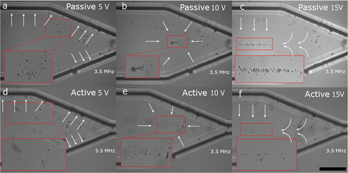
Further insights into the observed phenomena are obtained by introducing active bimetallic rods. Gold-platinum nanorods were mixed with H2O2 until a final concentration of 15%, reaching an average self-propulsion speed of 6 µm s-1 (See Figure S4, Supporting Information for the velocity distribution histogram). While active rods gathered close to the same area as passive at 10 Vpp at the center of the nozzle, no cluster was formed (Figure 2e). Instead, the nanorods collectively realigned and kept trying to escape the accumulation point, always propelling toward the nozzle wall. This phenomenon occurs until the focusing force becomes too strong and flushes them back. We observed an increase in the nanorod self-propulsion speed that can be associated with the effects of self-acoustophoresis. Also, the enhancement of the self-electrophoresis may occur due to the fast circulation of fuel around the particles as a consequence of acoustic streaming flows; see Video S3 (Supporting Information) for the accumulation of active nanorods at 10 Vpp. At 5 Vpp, the rods slowly migrated away from the accumulation point with no alignment observed. Only closer to the wall, they realigned and swam fast toward the corner (Figure 2d). (See Video S4, Supporting Information for active nanorods behavior at 5 Vpp). At 15 Vpp, active rods migrate to the centerline and, similar to passive rods, drift away from the nozzle outlet. In this case, active nanorods realign and swim along the centerline toward the nozzle inlet. (See Video S5, Supporting Information for active nanorods' behavior at 15 Vpp.)
The realignment of active rods against the focusing direction suggests that the effect may be caused by streaming fluid rather than acoustic radiation forces. Close to the bottom, the electrostatic and hydrodynamic forces tilt the rods with an angle φ to the surface (Figure 1d), making them behave similarly to a weather vane and align along the flow direction.[8, 9, 22]
For a slightly higher frequency of 3.8MHz, we observed another effect: opposing motion of individual particles and large clusters, Figure 3a. In that case, the accumulation point was formed closer to the outlet of the nozzle compared to the lower frequencies. Also, the configuration of the acoustic pressure node was different: point-like for the frequency of 3.5 MHz and more extended for 3.8 MHz. As a result, there was practically no trapping effect along the channel axis. Thus, single particles were moving away from the outlet. In the course of motion, they accumulated and formed clusters that moved toward the inlet. The clusters, in turn, shed particles that began to move in the opposite direction. The reversal of the direction of motion as a function of the cluster size can be qualitatively understood by comparing the drag force acting on the cluster that is proportional to the cluster size R with the radiation force that scales as R3, Figure 3b. The effects of these forces as a function of the particle radius was computed, see Figure 7c. There the sum of the viscous and radiation forces along the longitudinal direction of the channel shows that for the clusters with radius larger than 3 µm, the total force reverses its direction taking them away from the accumulation point and toward the outlet. (See Video S6, Supporting Information for opposing movement of single rods and clusters at 10 Vpp and 3.8 MHz.)


2.2 External Flow and Extrusion of Particles Through the Nozzle
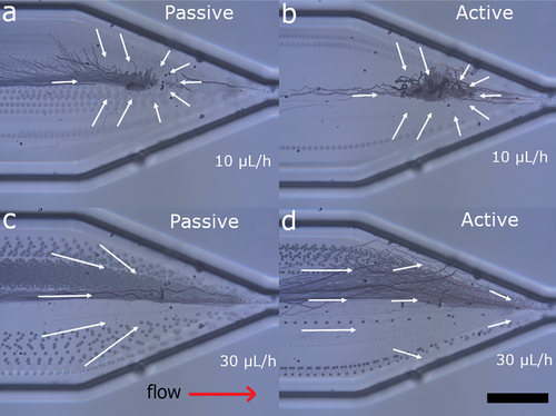
Practical applications of active particles are impaired by their cross-streamline migration and rheotaxis in the applied flow.[8, 9] Here we demonstrate how the acoustic field controls the extrusion and manipulation of active and passive particles during extrusion. We imposed flow rates ranging from 10 µL h-1 up to 50 µL h-1 in steps of 10 µL h-1, corresponding to average flow speeds of 100–500 µm s-1 (see Table S1, Supporting Information for the conversion to average flow speeds from flow rates). Most experiments were conducted at an acoustic field frequency of 3.5 MHz and an excitation voltage of 10 Vpp. Figure 4 shows a series of superimposed time-lapsed images of the particles inside the nozzle under these conditions. Here we observe that the extrusion of tracer spheres is less affected by the acoustic field. At slower flow rates, the tracers have more time to move up toward the acoustic pressure node, appearing more out of focus than at faster flow rates.
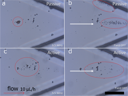
The behavior of passive nanorods is illustrated in Figure 4a–d. At the flow of 10 µL h-1, the juxtaposition of the external flow with the acoustic streaming allowed for selective filtering: trapping the rods in the accumulation point at the nozzle while permitting the flow of suspended PS tracers (Figure 4a). This phenomenon enables the extrusion of the rods in controlled bursts by applying the acoustic excitation in modulated pulses, as shown in Figure 5a,b. The rods are retained in the nozzle by the acoustic field and then released by turning the acoustic field off (See Video S7, Supporting Information for controlled extrusion of passive nanorods). For flows higher than 10 µL h-1, we observe that the external flow overcomes the trapping effect of the acoustic streaming only at the center of the channel. Consequently, the nanorods that were trapped in that region are later flushed through the nozzle, as shown in Figure 4c.
Similarly, active nanorods can be contained at flow rates up to 10 µL h-1, as observed in Figure 4b (See Video S8, Supporting Information for containment of active nanorods under an applied flow). However, for faster flows, contrary to previous experiments,[8] active nanorods did not oppose the external flow and escaped through the nozzle. We associate this behavior with the effective disruption of the orientation of the rods by the combined effect of the applied and streaming flows. By preventing the rods' realignment with the external flow, the rheotaxis was suppressed, and particles moved with the longitudinal component of the velocity. Moreover, we observed that at the fastest flow rates of 40 and 50 µL h-1, the effect of the applied flow helped the rods overcome the streaming flow directed from the wall and become trapped at the channel wall (See Video S9, Supporting Information for enhanced extrusion of active particles).
Modulation of the acoustic field amplitude can be used to extrude active particles as well, see Figure 5c,d. The streaming flows created by the acoustic field force active nanorods to concentrate in the central part of the nozzle, close to the centerline, as shown in Figure 5c. Unlike passive particles, active nanorods do not form a compact cluster; they circulate in a relatively large area restricted by the red circle. Upon switching off the acoustic field, active particles are flushed by the flow, as shown in Figure 5d. It occurs because the applied flow is fast at the centerline. It prevents the nanorods from reaching the nozzle wall, where they can rheotax against the flow.
2.3 Multiphysics Computational Modeling
We calculate the acoustic field and resulting streaming flows using a finite elements simulation platform COMSOL Multiphysics®. Our model consists of an extension to 3D of the model developed previously.[52-54] Apart from extending the equations to 3D, we added the effect of PDMS deformation and dampening by coupling the Solid Mechanics equations with the Thermoviscous Acoustic module. See Note S1 (Supporting Information) for acting forces, Note S2 (Supporting Information) for COMSOL simulation details, Figures S5 and S6 (Supporting Information) for the explanation of the simulation domains and boundary conditions, and Video S10 (Supporting Information) for PDMS deformation. The Thermoviscous Acoustic module is required to accurately model acoustics in small samples. The existence of thermal boundary layers near walls makes viscous losses and thermal conduction very important. In our model, the Thermoviscous Acoustic module allows for solving the nonlinear terms in the Navier-Stokes equation that do not appear in regular Pressure Acoustic physics. Since tracking active nanorods is challenging in the COMSOL environment, and the behavior of passive particles is determined by the balance of the acting forces that are shown in the plots extracted from the simulations, we did not include Particle Tracing module.
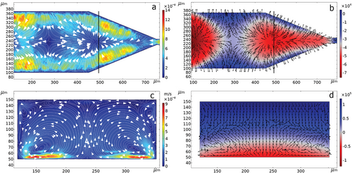
Figure 6a,b depicts the velocity magnitude and pressure distribution at the channel in a horizontal plane 1 µm from the bottom. In this location, the two forces acting on this plane are opposed. While the acoustic radiation force pushes the particles toward the channel walls, the streaming flow carries the particles toward the accumulation point. Figure 6c,d show the same variables but in a transverse plane located along the black line shown in Figure 6a,b. Here, we can observe a rapid flow only close to the viscous boundary layer at the rigid bottom of the channel and not a strong effect at the PDMS walls. Figure 6d shows that the acoustic pressure node is located on a surface at a certain distance from the bottom. The movement of the PS tracers in our experiments coincides with the direction of the acoustic radiation force. That is due to their larger size, which makes the effect of the radiation force dominant over the flow drag (radiation force scales as the cube of particle size, whereas drag force is proportional to the particle size). It is because of the smaller force needed to overcome the effective gravity Fge (gravity minus buoyancy force) compared to the much denser nanorods that stay closer to the bottom. As for the excitation amplitude, we used the piezoelectric constant provided by the manufacturer of the piezoelectric device, d33 = 5 × 10⁻¹⁰ m V-1. But we did not consider the losses occurring in the epoxy and the silicon wafer. Hence, the simulations' radiation force and streaming flow velocity are somewhat larger than those observed in the experiment.
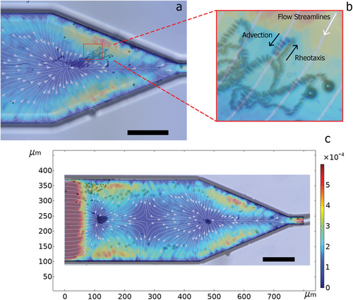
The dynamics of focusing versus separation of the nanorods can then be explained by considering the balance of forces acting on the vertical axis. From the simulations, we obtain that in this axis, both the radiation force Frad and drag force Fdrag generated by the fluid streaming oppose the effective gravity Fge. Due to this force balance, the levitation plane of the nanorods depends on the acoustic field amplitude. We used the 3 µm tracers stuck to the bottom of the channel as a reference. Since our microscope lens had a depth of field of 1.5 µm, we observed that the nanorods moved in or out of focus when the voltage was changed from 5 Vpp or 10 Vpp. Figure 7a shows the sum of the radiation force and the drag force in the transversal plane of Figures 6c,d at heights of 1.5 µm, corresponding to 5 Vpp, and 2.5 µm corresponding to 10 Vpp (see Acting Forces in Note S1, Supporting Information). Due to the steep gradient of the streaming velocity in that range, the force balance changes from a radiation force-dominated behavior closer to the bottom to a fluid steaming force-dominated movement in the higher layers. The strong shear rate of the flow in the vertical direction reorients the active particles against the flow, generating localized rheotaxis and the subsequent advection back when the flow velocity increases closer to the wall, as shown in Figures 8a,b. See Video S11 (Supporting Information) for a superposition of finite element velocity calculation with an experimental video of active nanorods focusing. At the voltage of 5 Vpp, the shear is only strong in a small section close to the walls. Hence, active rods only align in its proximity, supporting the hypothesis of flow reorientation, Figure 7b. Figure 7a shows in black dashed lines that at the voltage 10 Vpp, there is a threshold close to the wall where the fluid streaming force rapidly decays, and radiation force dominates, trapping the particles at the corner, as observed in the experiments. Simulations also predicted additional accumulation points further back from the nozzle, which we later observed at a lower magnification, as shown in Figure 8c.
Similar arguments likely explain the backward migration of particles at 15 Vpp, as shown in Figure 2c,f and in Video S2 (Supporting Information). At 10 Vpp, particles aggregate into a cluster at the pressure node, as shown in Figure 2b. The cluster is stable because the drag forces due to the streaming flows exceed the opposing radiation forces. Increasing the voltage to 15 Vpp increases the vertical component of the radiation force and shifts the levitation plane up. It leads to attenuation of the drag force compared to the radiation force. As a result, the cluster begins to move backward.
2.4 Conclusion
We overcame the challenge of focusing small active particles with acoustic fields by designing a microfluidic channel, where the effects of ultrasound dampening and the complex geometry enable the harnessing of acoustic streaming flows. Under these experimental conditions, tracer spheres, passive nanorods, and active nanorods exhibit significantly different behaviors. While tracer PS spheres are driven mainly by the acoustic radiation force and taken out of the bottom plane, nanorods stay at the bottom, at a levitation plane defined by the balance of gravity, buoyancy, acoustic radiation, and fluid streaming. Hence, by controlling the intensity of the applied acoustic field, rods can be focused on an accumulation point in the nozzle by means of acoustic streaming flows or driven toward the walls at low amplitudes when the radiation force controls their dynamics. Active nanorods, however, can reorient against the flow (due to rheotaxis) and oppose the effects of the focusing forces. This phenomenon, which could be harnessed for cargo delivery, is engineered in a way to inhibit the upstream swimming of self-propelled particles and allow them to be flown through the channels. While we observed the effects of the enhanced self-propulsion, further studies are needed to quantify the influence of self-acoustophoresis and the enhanced self-electrophoresis due to rapid flows around the nanorods.
The application of acoustic fields solves the main problem of active particle extrusion and manipulation. We extrude the particles even at lower flow rates by disrupting the active nanorods' alignment against the flow. Moreover, the geometric effects of the nozzle create an acoustic focusing point instead of the more common focal plane or line. This design permits the selective extrusion of passive and active rods for up to a certain flow rate threshold and opens the possibilities of controlled deposition of active nanorods.
The potential applications of this system include targeted acoustic cargo delivery, injection, and additive manufacturing by the deposition of active materials as smart additives in 3D printers. Our study sheds light on the possibility of using acoustic fields to precisely tune particle distribution and orientation when extruded through nozzles.
Here, we demonstrated how an acoustically powered nozzle could control properties like particle orientation and concentration during extrusion. However, the fuel (H2O2), which propels the nanorods, is often incompatible with many of the materials currently used for 3D printing. It is also a deterrent for biological applications because of its high reactivity. Our study demonstrates phenomena and engineering solutions that apply to many active particle systems that could be used in these applications. Alternatively to H2O2, bio-compatible chemical reactions can be used to generate self-propulsion, e.g., using enzymatic catalysis. [55]
3 Experimental Section
Experiments were performed in a polydimethylsiloxane (PDMS) microfluidic channel on top of a 51 mm silicon wafer with a piezoelectric transducer (SMD12T06R412WL; Steminc, Davenport, FL, USA), resonant frequency 3.4 MHz, attached below with epoxy adhesive (Hysol 1C; LOCTITE, Hartford, CT, USA). The signal to the piezoelectric transducer was delivered by a wave function generator (AFG3022C; Tektronix, Anaheim, CA, USA) and amplified (Model 40A12; Amplifier Research, Souderton, PA, USA). The signal amplitude was monitored using an oscilloscope (TDS2001C; Tektronix, Anaheim, CA, USA). The images were acquired using a microscope (BX40, Olympus, Shinjuku City, Tokyo, Japan) in reflected light mode and a camera (Prosilica GT 1660C; Allied Vision, Stadtroda, Germany). The flow was controlled with a microfluidic pump (Cetoni Nemesis Low Pressure; Cetoni, Korbußen, Germany) and 250 µL glass syringes (Hamilton 1700 Series; Hamilton Company, Reno, NV, USA) connected to the microchannel using polyethylene tubing (PE 10, Becton Dickinson and Company, Franklin Lakes, NJ, USA). 3 µm PS tracers were added to the suspension (Fluoro-Max G0300; Thermo Scientific, Waltham, MA, USA ).
Electrodeposition Synthesis of Nanorods
Au–Pt bimetallic nanorods were fabricated by electrodeposition in anodic alumina membranes (AAO, Whatman Inc., Buckinghamshire, United Kingdom).[56] A three-electrode system was used, and the backing electrode was formed from evaporating a thin layer of silver onto the backside of the AAO membrane. The counter-electrode was Ag/AgCl with a Pt coil wire reference electrode wrapped around the counter electrode. First, a 1 µm sacrificial layer of silver was deposited into the AAO template. Next, 1 µm of gold and 1 µm of platinum were deposited. The sacrificial silver layer was then etched away with 5M nitric acid for 10 min, and the AAO template was etched away with 1M sodium hydroxide for an hour. The rods were collected by centrifugation and sonication and stored in hydrogen peroxide. Passive rods were cleaned in deionized water for experiments.
Acoustic Microfluidic Device Fabrication
The lithography master molds for the microfluidic nozzle were prepared following a previously reported procedure.[8] Polydimethylsiloxane (PDMS) (SylgardTM 184, Dow Corning, Midland, MI, USA) elastomer solution was prepared by combining the prepolymer and cross-linking agent in a weight ratio of 10:1 and poured over the microchannel masters to the desired thickness. The PDMS mixture was degassed in a vacuum desiccator for 30 min to remove any air bubbles and then cured in an oven at 60°C for 3 h. Next, the PDMS microchannels were removed from the mold, and the inlets/outlet were punched out with a 0.5 mm biopsy punch. The resulting channels adhered to silicon wafers by exposing the PDMS and silicon wafers to oxygen plasma and pressing them together. The piezoelectric transducer was attached to the silicon wafer under the microchannel with epoxy glue. The center of the transducer was carefully aligned with the center of the nozzle. After 24 h, once the epoxy glue hardened, polyethylene tubes were inserted into the inlet and outlet openings.
Image Analysis
Image analysis of the experiments was performed with a custom Matlab script. Particles, clusters, and tracers were identified and filtered by shape and size. A tracking function allowed extracting the trajectories and velocities of the particles for obtaining the data in Figure 3b and calculating the MSD and velocity distribution shown in Figures S3 and S4 (Supporting Information).
Acknowledgements
This research was supported by the U.S. Department of Energy, Office of Science, Basic Energy Sciences, under Award no. DE-SC0020964.
Conflict of Interest
The authors declare no conflict of interest.
Author Contributions
LDR and MC performed the experiments and analyzed the data, LDR and ISA developed multi-physics model, ISA and AS designed and supervised the research, all authors wrote the paper and discussed the results.
Open Research
Data Availability Statement
The data that support the findings of this study are available in the supplementary material of this article.


