3D Hollow Xerogels with Ordered Cellulose Nanocrystals for Tailored Mechanical Properties
Abstract
Advanced materials with aligned cellulose nanocrystals (CNCs) have attracted much attention due to their remarkable mechanical and optical properties, but most of them still focus on 1D or 2D architectures. Herein, complex 3D architectures as pseudo catenoid hollow xerogels with aligned CNCs are prepared from dynamic hydrogels by mechanical stretching and air-drying process. Aligned CNCs endow the pseudo catenoids with distinct birefringence in addition to reinforcement. The mechanical properties of pseudo catenoid architecture are revealed for the first time to be controlled at two stages on diverse length scales. Both the aligned CNCs on the nanoscale and the geometry of the xerogels affect the mechanical properties. The inwardly curved surface of the pseudo catenoid xerogel makes the structure conducive to energy dissipation. These both stages of controls on the mechanical properties can be adjusted by changing the morphology of the initial hydrogels and the mechanical stretching ratios. These results will provide a new perspective for the design and manufacture advanced materials with tailored mechanical properties and functions.
1 Introduction
The native anisotropic nanoparticles, among others CNCs, have been explored as reinforcing elements in a wide variety of synthetic composites due to their attractive characteristics, such as high aspect ratio, superior mechanical properties, low density and low coefficient of thermal expansion.[1] CNCs show diverse mechanical properties due to their anisotropic shapes, and the elastic moduli in the long axis is much higher than that in the transverse directions.[2] By controlling the alignment of CNCs during processing, great stiffening effects can be realized on obtained materials. Moreover, aligned CNCs can be applied in many fields in addition to enhancing materials strength, such as to modify surface properties, for the fabrication of structure colors and advanced textiles as well as for tissue engineering.[3-7]
Currently, CNCs can be oriented in an external electric field or magnetic field, as well as by mechanical shearing, spin-coating, dip-coating, dry/wet spinning or electrospinning.[8-12] However, these techniques are generally limited on producing 1D or 2D structures, such as fibers or films, respectively. More recently, extrusion-based techniques, including 3D/4D printing that enables programmable assembly, have demonstrated the potential to align CNCs during the printing process and gained research interest for the preparation of composite materials with complex architectures.[13-16] Such 3D structures with complex architecture generally have non-continuous surface, especially in the vertical direction. Moreover, many printing parameters in these techniques affect the alignment of CNCs within the final 3D geometries, such as inherent rheology/viscosity of ink, shear rate, nozzle geometries and the choice of coagulant.[17, 18]
Furthermore, another serious issue encountered in the complex 3D architectures containing CNCs is the mechanical properties of the structures. Although previous studies have successfully fabricated complex 3D architectures regardless of the methods employed,[13] almost no studies have been conducted on the mechanical properties of these structures and the role of CNCs for the mechanical properties of these 3D structures. Previous reports have demonstrated that increased alignment of CNCs led to enhancement in the mechanical properties of the produced materials, but this was only demonstrated on 1D/2D structures. However, the effect of aligned CNCs on the mechanical properties of 3D architectures is still unknown, never saying about the importance of CNCs on the mechanical properties in comparison to other parameters, such as geometry of a certain 3D shape.
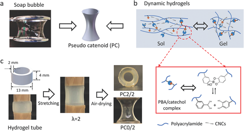
Herein, we fabricate the complex 3D architecture as pseudo catenoid (PC) with aligned CNCs by mechanical stretching and air-drying process of dynamic precursor hydrogels. Catenoid, arising by rotating a catenary curve around an axis, has the remarkable property of be a minimal surface, i.e., a surface of the least area.[19] One typical case of catenoid in our daily life is the soap bubble between two open rings (Figure 1a). If the gravity could be ignored compared to the surface tension, this shape can be regarded as ideal catenoid, which is dominantly driven by the surface tension of liquid system. Based on the mechanical stretching and air-drying process, CNCs in the dynamic hydrogels can be unidirectionally aligned, providing additional optical property in addition to reinforcement. The specific forms of the obtained PC structures could be highly controlled by the morphology of the original hydrogels and the extent of the mechanical stretching. The surface of the PC structure can be further optimized with the assistance of air-drying process governed by minimizing surface tension, leading to the smooth, continuous and curved surface. Most importantly, it is the first time to show that the mechanical properties of complex 3D shaped structures simultaneously relied on the alignment of CNCs and the inherent geometry of the architecture. These results will give new sights to design and manufacture advanced materials with tailored morphology, mechanical properties and functions.
2 Results and Discussion
2.1 Fabrication of the Hollow Pseudo Catenoid (PC) Structure
The detailed process for the preparation of the hollow PC structure was illustrated in Figure 1. This special structure was fabricated via mechanical stretching and then air-drying process of dynamic hydrogels, which were prepared by in situ polymerization of acrylamide in borax-NaOH buffer solution (pH = 10) with 3-(acrylamide) phenylboronic acid (PBAAm)/dopamine methylacrylate (DMA) complexes as dynamic crosslinkers (Figure 1b). CNCs with 90–300 nm in length and about 10 nm in diameter were prepared via TEMPO-mediated oxidation and could be added into the hydrogel precursor (Figure S1, Supporting Information). They contained carboxyl groups of 1.50 ± 0.02 mmol g−1 and aldehyde groups of 0.12 ± 0.02 mmol g−1 on the surface, allowing them to be well dispersed in neutral or weak alkaline aqueous solutions for the preparation of dynamic hydrogels.[20] The abundant hydroxyl and carboxyl groups on CNCs could interact with amide groups on polyacrylamide chains through hydrogen bonding (Figure S2, Supporting Information). Obtained dynamic hydrogels showed the typical shearing thinning property (Figure S3, Supporting Information), which is because of the quick temporary dissociation and reconstruction of PBAAm/DMA complexes.[20, 21] This reversible transition of dynamic solution-gel states with corresponding tunable viscosities was maintained during the programming and shaping of dynamic hydrogels (Figure 1b). This property allowed the preparation of the hollow PC structure by using hydrogel tubes via mechanical stretching. During the further long-time drying process of stretched hydrogel tubes, the evaporation of water drove shrinking hydrogels with smaller volumes, and the surface tension led to the smallest surface area in the resulted xerogels. Indeed, this air-drying process is a self-organization process of the hydrogel tube under certain strain stress to promote the spontaneous formation of the hollow PC structure. Figure 1c presents the typical hydrogel tube (containing 2 m acrylamide with PBAAm/DMA complexes and 2 wt% CNCs) after stretching with the elongation ratio (λ) of 2 and hollow PC2/2 xerogel after air drying. With the same method, more transparent PC0/2 xerogel without CNCs also can be achieved. (PCx/y, x means the weight percent of CNCs in the dynamic hydrogel; y means elongation ratio (λ)).
2.2 Regulation of the Morphology of Hollow PC Structure and their Optical Property
There are two key factors that affected the formation of the PC structure. One is the hollow geometry of the precursor hydrogel tube, which is critical for the air-drying process. Generally, the drying of bulk hydrogels starts from the surface and proceeds slowly to the interior, while the shape change is largely governed by internal stress and surface tension. The influence of these parameters can be strongly offset within the hydrogel tubes, because the water loss from the thin hydrogel wall will happened on both inside and outside at the same time. Another key factor is the appropriate morphology control. During the stretching process of the dynamic hydrogels, the tensile stress increased dramatically up to λ = 3 and increased slowly with higher λ (Figure 2a). Therefore, the morphology control of PC structures will be highly affected during the stretching process. Although the hollow shape could favor the formation of PC structure, the wall of hydrogel tubes still has a certain thickness. This thickness is generally much higher than the soap bubble layer (Figure 1a) and can generate different curvatures of the inside and outside surface of the tubes. Compared to the dimension of hydrogel tubes, the wall thickness needs to be small enough to minimize its influence, especially for the structures with higher elongation ratios. Consequently, the morphology of PC0/10 xerogel with much larger outlayer diameter (D = 26 mm) and comparably much smaller wall thickness (T = 2 mm) was more optimized than that with D/T = 13/2 (Figure 2b). Besides, higher elongation ratio than λ = 2 with the same diameter/thickness (D/T) ratio drove the structure away from the ideal catenoid shape. Consequently, the larger D/T ratio and appropriate elongation ratio led to hollow PC structures with a concaved surface approaching the ideal catenoid.
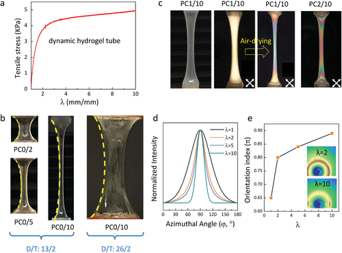
Thanks to the mechanical stretching process during the fabrication of the PC structure, the CNCs in the dynamic hydrogels can be unidirectionally aligned, leading to vivid birefringence phenomenon and providing the additional optical property for this structure. Moreover, the subsequent air-drying process further promoted the orientation of CNCs within the polymer matrix. As shown in Figure 2c, the hydrogel tube of PC1/10 after mechanical stretching presented light yellow interference color between the crossed polarizers. After air-drying, the interference colors of the xerogel became more obvious (blue), which shows further alignment of CNCs in addition to the optimization of the curved surface during the air-drying process. Besides, PC structure with different CNCs contents showed different birefringence as shown by PC1/10 and PC2/10 (red), indicating the different alignments of CNCs within the xerogels.
Importantly, larger elongation ratios (λ) of stretched dynamic hydrogels could promote the alignment of CNCs in the xerogels, generating more vivid birefringence colors. As verified in Figure 2d,e, the PC structures showed much stronger angle dependence in the diffraction patterns by increasing the elongation ratios from 1 to 10. The corresponding orientation indexes of CNCs in the PC xerogels increased from 0.66 to 0.89, showing enhanced alignment of CNCs. Only with sufficient elongation ratio of larger than λ = 2, the PC structure contained well aligned CNCs and exhibited adjustable birefringence, generating diverse vivid colors of obtained PC xerogels (Figure S4, Supporting Information). Therefore, the optical property of the PC structure can be a visual evidence of the alignment of CNCs, which is highly affected by the contents of CNCs and the elongation ratio.
2.3 Mechanical Properties of the Pseudo Catenoid Structure
In general, the alignment of CNCs within the materials could highly affect the mechanical property.[22, 23] Herein, the mechanical properties of PC structure with various CNCs contents and elongation ratios were investigated.
On the one hand, stronger stretching of initial hydrogels tubes will largely reduce loading capability of the resulting PC xerogels, even though the orientation index of CNCs within the structure enhanced (Figure S5, Supporting Information). As shown in Figure 3a,b, the ultimate fracture forces of the PC xerogels without CNCs or with 2 wt% CNCs decreased dramatically with increasing λ. The specific parameters of PC xerogels with various λ were presented in Table S1 (Supporting Information). When λ = 1 and 2, the ultimate fracture force of the PC xerogels was not significantly affected by the CNCs contents (Figure 3a,b,d), indicating the decisive role of geometry in the xerogel tubes obtained with low elongation ratios. Interestingly, the concave surface can transfer the vertical deformation to the confinement toward the center of PC. Therefore, all the rupture of PC xerogels without CNCs were broken toward the inside of the tubes, as illustrated in Figure 3c. On the other hand, CNCs will reinforce the mechanical properties of the xerogels, and switch the plastic rupture to the brittle rupture mode, as shown in Figure 3b. In particular, CNCs effectively improved the ultimate fracture force in the largely stretched PC xerogels with λ = 5 or 10 (Figure 3d), but little enhancement in the short xerogel tubes (λ = 1, 2). Furthermore, CNCs also enhanced the Young's modules in the largely stretched PC structures, which can be verified from the slopes of the curves in Figure S6 (Supporting Information), showing the enhanced stiffness in PC xerogels containing CNCs. In addition, the brittle rupture on one side of PC xerogel with CNCs (Figure 3c) also demonstrated the enhanced stiffness by CNCs incorporation. The enhanced mechanical property of largely stretched PC structure can be attributed to the enhanced alignment of CNCs (caused by increased CNCs contents) within the xerogels, which can compensate the geometry disadvantage resulted by strong stretching.
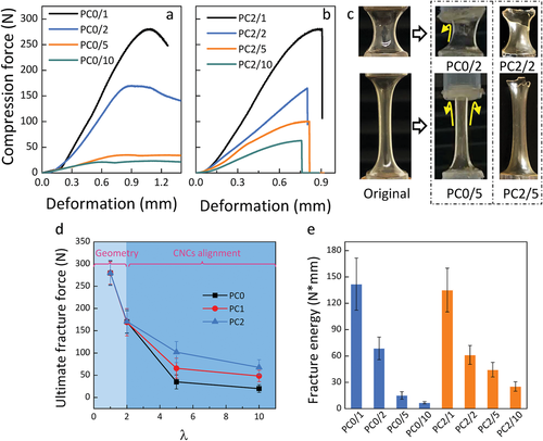
Consequently, the mechanical property of PC structure can be divided into two stages. As illustrated in Figure 3d, the first stage was controlled by the inherent geometry of PC structure, while the second stage was mainly taken over by the contents of aligned CNCs. Figure 3e presented the fracture energies (Gf) of PC xerogels. Herein Gf was defined as the work needed in creating the fracture surface. Generally, Gf decreased with increasing λ regardless of the presence of CNCs, indicating the gradually weaker mechanical strength caused by larger λ. However, Gf of PC xerogels containing CNCs were much higher than that without CNCs for PC with larger λ. Higher Gf further verified the effective enhancement of the mechanical strength by aligned CNCs and this alignment further compensated the morphological defect caused by the larger λ. Therefore, the mechanical properties of PC xerogels were primarily controlled by geometry (small λ) and contents of aligned CNCs (large λ), respectively. In addition, PC xerogels with λ = 2 seem to be highly suitable parameters for PC structures, considering their good mechanical property, alignment of CNCs and continuous PC morphology.
The curvature surface of hollow PC generated by the effects of tension and self-organization of CNCs could give rise to the special mechanical performance. For better understanding the geometry of PC structure, the cylinder xerogels without tension were prepared, where water loss only happened on the outside of hydrogel tube (Figure 4a). Herein, the finite element analysis was employed for better illustrating the stress distribution and deformation of various samples. As shown in Figure 4b-c, the catenoid samples could avoid the stress concentration in local region compared with cylinder samples, endowing the catenoid samples with higher elongation at break and better energy dissipation ability. This result also can be demonstrated by mechanical test. As shown in Figure 4d, the cylinder xerogels with/without CNCs exhibited much higher ultimate fracture forces than PC, but their compression curves presented several turning points before the structure completely broke or the force disappeared, as demonstrated in Figures S7 and S8 (Supporting Information) for the details. Besides, the cylinder xerogels without CNCs presented the typical yield point before it completely broke, as shown in Figure 4e. The bottom of the cylinder xerogels became irregular which caused many turning points on the curves during compression. After incorporated with CNCs, the cylinder structure almost maintained its original shape during the compression process, and the structure presented a brittle rupture in the vertical direction, thereby exhibiting higher stiffness than that without CNCs. Especially, compared with cylinder structure without CNCs, the curve of cylinder xerogels containing CNCs tended to exhibit a small rupture around 250 N due to the enhanced stiffness caused by CNCs. These small yield points of cylinder xerogels can be adapted by themselves during the compression process, leading to the higher ultimate fracture forces. This can be mainly attributed to the vertical surface of cylinder that could bear larger force along the axis than the curvature surface of PC. Nevertheless, these results indicated that the cylinder xerogels suffered from an irreversible and nonfatal deformation under this compression. To be strictly accurate, the fracture energy of cylinder xerogels will be calculated before the first yield point of the compression curves, instead of the highest ultimate fracture force. Consequently, the fracture energy Gf of cylinder xerogels didn't present more advantages than PC, especially the one with CNCs (Figure S9, Supporting Information).
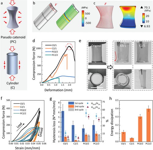
In addition to this first-cycle static compression process, PC geometry presented a distinct advantage during the multiple compression cycles. Figure 4f and Figure S10 (Supporting Information) showed the cyclic compression curves of as-prepared PC and cylinder xerogels at almost the same strain (≈5%). Without intervals between each compression cycle, the second hysteresis loop of cylinder xerogels became much smaller and narrower compared with those of PC. Cylinder structures were actually impaired after the first compression. Importantly, the third hysteresis loop of PC xerogel was almost overlapped with the second hysteresis loop, showing the stable mechanical property of PC structure. Accordingly, the hysteresis losses of three cycles for various samples have been presented in Figure 4g, with two key points that can be concluded. Firstly, from the perspective of geometry, like C0/1 and PC0/2, though cylinder structure showed higher hysteresis loss than PC in the first compression cycle due to the much higher compression force, the hysteresis losses of its second and third cycles decreased dramatically. Instead, PC geometry demonstrated a better energy dissipation system, because the hysteresis losses of the second and third compression cycles for PC geometry were higher than that of cylinder geometry, and the hysteresis losses of the second and third compression cycles for PC can keep about 50% of the first cycle, while for cylinder geometry, they only maintained about 10% of the first cycle. In addition, this more efficient energy dissipation system of PC structure also can be verified in Figure 4h. The energy dissipating efficiency of cylinder xerogels C2/1 was only less than 5%, while the energy dissipation of PC2/2 was about 40%. Thence, the PC geometry shows a better energy dissipation system by relaxing most of compression energy. This should be due to the fact the inwardly curved surface of PC structure can transfer the laterally inward extrusion to resist the vertical deformation (Figure 4a–c), leading to the better energy dissipation. Secondly, different than the geometry, the incorporation of reinforcing stiff CNCs did not favor the energy dissipation in both PC and cylinder structures. Specifically, the hysteresis losses of the three cycles for cylinder structure with CNCs was much lower than that without CNCs. Moreover, CNCs only slightly increased the hysteresis loss of PC xerogels, showing little effects of CNCs on energy dissipation. In a word, though the PC geometry did not bear as much compression force as cylinder structures did during the first compression, it showed more efficient energy dissipation and can stably withstand loading of multiple cycles.
3 Conclusion
In summary, we fabricated the complex 3D architecture of pseudo catenoid hollow structure by mechanical stretching and air-drying process of dynamic hydrogel. Based on this method, this pseudo catenoid structure showed vivid birefringence because of the anisotropically aligned CNCs within the polymer matrix, endowing additional function for resulted geometry. The morphology of the initial hydrogels, mechanical stretching process and air-drying process all contributed a lot for the final formation of the pseudo catenoid structure. Notably, the mechanical property of pseudo catenoid structure was highly controlled by the geometry and the alignment of CNCs. Compared with the cylinder structure with vertical surface, the produced pseudo catenoid structure exhibited better energy dissipation mechanism because of its inwardly curved surface. These results are instructive for designing and manufacturing materials with special structures and functions, such as shock absorption, strut construction and so on.
4 Experimental Section
4.1 Materials
Microcrystalline cellulose (MCC), 2,2,6,6-tetramethylpiperidine 1-oxyl (TEMPO), 3-(acrylamido) phenylboronic acid (PBAAm), methacrylic anhydride, sodium hydrochloride, phosphotungstic acid hydrate, 2,4,6-trimethylbenzoyl chloride were purchased from Sigma-Aldrich (Germany). Dopamine hydrochloride, dimethyl phenylphosphonite, and 2-butanone were obtained from Alfa Aesar (Germany). Acrylamide, sodium sulfate anhydrous, disodium tetraborate were bought from Merck KGaA (Germany). Sodium hydroxide was received from VWR (Germany). The borax-NaOH buffer (pH = 10) was bought from TH Geyer (Germany). All solvents used as received were supplied by TH Geyer (Germany). Dopamine methylacrylate (DMA) and lithium phenyl-2,4,6-trimethylbenzoyl-phosphinate (LAP) were synthesized according to previous reports.[24, 25]
4.2 Preparation of CNCs
CNCs were prepared with TEMPO-mediated oxidation of MCC according to the previous reports.[20, 21] Obtained stable suspensions were stored in a refrigerator at 4°C for further use.
4.2.1 Preparation of Dynamic Hydrogels
Dynamic hydrogels were prepared according to the previous work.[20] In detail, the dynamic hydrogels contained 2 m acrylamide, and dopamine methylacrylate (DMA)/3-(acrylamide) phenylboronic acid (PBAAm) were added in the quantity of 1.25 mol% of acrylamide. At the same time, CNCs suspension was centrifuged and redispersed in borax-NaOH buffer solution (pH = 10). Lithium phenyl-2,4,6-trimethylbenzoyl-phosphinate (LAP) (0.5 wt%) was used as photoinitiator. The final buffer concentration of hydrogel precursors was 0.025 m and they were purged with N2 or argon gas for 3 min to remove dissolved oxygen. Then, they were exposed to UV light (352 nm, 15 W) for 30 min to finish the gelation process.
4.2.2 Preparation of Hollow Pseudo Catenoid and Cylinder Structures
Hollow PC xerogels were prepared from hydrogels tubes with a Z3 micro tensile test machine from Grip-Engineering Thümler GmbH. The typical tensile process of as-prepared dynamic hybrid hydrogels was performed at 20 °C and a relative humidity of 65% with uniaxial stretching speed of 2.5 mm min−1. The following air-drying process was performed on the tensile test machine at 20 °C and a relative humidity of 65% until constant weight. While the cylinder structure was prepared from the cylinder precursor hydrogels, which were air-dried on glass tubes.
4.2.3 The Simulation of Stress Distribution on Cylinder/Catenoid Samples
A COMSOL Multiphysics software was applied to realize the simulation of stress distribution. The surface load perpendicular to cross section was set as 1000 and 100 N for cylinder and catenoid samples respectively, according to the compression test results. The modulus was set based on actual test and Poisson's ratio of materials was regarded as 0.4. Considering the geometry parameters of samples, a plate stress analysis and Scordelis–Lo Roof Shell Benchmark model were used for cylinder and catenoid samples separately.
4.3 Characterization
The tensile test of dynamic hydrogels and the compression tests of xerogels were carried out on a Z3 micro tensile test machine from Grip-Engineering Thümler GmbH. The rheological properties of hydrogels were investigated with a stress-controlled bulk rheometer (Anton Paar MCR501) by using a 25 mm parallel-plate setup at room temperature (23 °C). Storage modulus (G′), loss modulus (G″), damping factor, and complex viscosity were recorded. The wide-angle X-ray scattering (WAXS) of the xerogels was carried out at the Shanghai Synchrotron Radiation Facility (SSRF) on the BL16B beamline with an X-ray wavelength of 0.124 nm. The orientation index (π) of CNCs was calculated according to the method reported in the previous work.[21]
Acknowledgements
Y.Y. and H.H. contributed equally to this work. K.Z. thanks German Research Foundation (DFG) for the project with the project number ZH546/3-1 for the financial support. K.Z. thanks the Ministry of Science and Culture of Lower Saxony, Germany for the financial support of the program “Material Science Wood”. Y.Y. thanks the National Natural Science Foundation of China (22005103) and China Postdoctoral Science Foundation (2019M652905) for the financial support. D.X. and X.J.W. thank China Scholarship Council (CSC) for the financial support.
Open access funding enabled and organized by Projekt DEAL.
Conflict of Interest
The authors declare no conflict of interest.
Open Research
Data Availability Statement
Research data are not shared.


