3D Printing of Aluminum Alloys via Material Extrusion (MEX) Process: Challenges in Developing Acetone-Soluble Binder Systems
Funding: This work was supported by Österreichische Forschungsförderungsgesellschaft (project name: AlF3, Project No.: 885128).
ABSTRACT
Metal material extrusion (MMEX) is a technique to produce a part, characterized by the sequential deposition of material in layers, which is subsequently followed by debinding and sintering to yield fully dense metallic components. The feedstocks, consisting of metal powder combined with a binder system, are essential in determining both the processability and the final attributes of the manufactured parts. In this study, differential scanning calorimetry (DSC) and thermogravimetric analysis (TGA), contact angle measurement, rheological measurements, printability, and solvent debinding tests were performed for developing a binder system for MMEX of aluminum alloys. Various binder system formulations with polypropylene (PP) as the backbone along with different thermoplastic elastomers (TPEs) as the soluble part were used. During the solvent debinding, two different solvents, cyclohexane and acetone, were evaluated. The results indicated that acetone was ineffective as a solvent for the TPEs used in this study, primarily due to the low solubility of the TPEs in acetone. However, more than 90 vol% of the TPE was removed using cyclohexane as the solvent even at room temperature. Ultimately, the optimized binder formulation for the MMEX process of the aluminum alloys was chosen to consist of polypropylene (PP) as the backbone and thermoplastic elastomer (TPE) soluble in cyclohexane as the primary component. This formulation successfully facilitated all stages of the MMEX process, from shaping to sintering.
1 Introduction
Additive manufacturing (AM) has gained significant attention recently due to its capability to create lightweight components. Consequently, aluminum alloys, recognized for their low density and high strength, are essential materials in AM for producing lightweight products. Aluminum (Al) alloys are divided into two categories: wrought alloys and cast alloys. Cast aluminum alloys contain a significant amount of silicon, which provides excellent fluidity and strength, making them suitable for creating complex shapes and handling high-stress applications. These alloys are widely used in various industries, including automotive, aerospace, construction, and electronics, due to their lightweight nature, corrosion resistance, and versatility in fabrication processes. In contrast, wrought alloys are commonly employed in aerospace components, automotive parts, bicycle frames, and marine hardware. Their strong strength-to-weight ratio, corrosion resistance, and ease of welding make them ideal for these applications [1-3].
The limitations of current AM technologies, such as powder bed fusion of Al using a laser beam (PBF-LB/Al) (notably, high equipment cost and the handling of reactive powder), can potentially be mitigated by adopting filament printing [4, 5]. Filament printing offers additional advantages, including the capacity to combine multiple materials within a single component and the creation of enclosed cavities within structures [6, 7]. Nowadays, there are devices that can directly melt, extrude, and deposit Al wires to build three-dimensional objects [8, 9], but they are currently best suited to welding Al grades with lower mechanical properties. Therefore, Metal Material Extrusion (MMEX) could still be an alternative to process wrought and cast Al alloys.
MMEX closely resembles conventional metal injection molding (MIM), where green parts are shaped, debound, and sintered (SDS) to obtain metal specimens [10, 11]. Given the similarity in process steps between MIM and MMEX, the development of binder systems for MMEX can leverage the knowledge and experience acquired from the development of MIM binder systems [12-14]. In the initial step of MMEX, green parts are fabricated using a metal/polymer composite filament, where the polymer acts as a binder and is melted, while the metal particles remain solid. Following this, brown parts are produced by debinding the green parts, which removes most of the binder. This is usually done by solvent or catalytic debinding. The residual binder in the brown parts prevents the metal particles from separating, thereby maintaining the shape of the parts. Finally, during thermal debinding and the first stage of sintering, the remaining polymer decomposes, and the sintering process compacts the metal particles into a dense solid [15, 16].
Employing SDS with MEX for Al offers a promising cost-effective production method for parts with complex geometry. However, to produce the filaments needed for MMEX, the thermoplastic binder system must be filled with at least 45 vol% of metal powder. The filament is needed to feed the 3D printer with the material required to shape the specimens [17-21]. High filling is important because only then is it possible to employ pressureless sintering.
The development of a binder composition that meets the requirements for the shaping (i.e., 3D printing) step as well as the debinding and sintering step is a challenging endeavor [22]. For the printing step, the filaments should have a combination of the following characteristics—tough, flexible, and low viscous when molten [21, 23]. The debinding step necessitates at least a dual-component binder system, wherein one component is soluble in a solvent, while the other is resistant to it. The insoluble component is referred to as the binder's backbone. Furthermore, the backbone components must have a thermal degradation temperature (much) lower than the sintering temperature of Al [24]. This presents a particular challenge, as the sintering temperature of Al is close to the degradation temperature of most thermoplastics [25, 26]. It is crucial to completely remove the binder to minimize the residual oxygen and carbon levels, which can significantly impact the quality of the sintered part or, in some cases, can make sintering impossible.
Several research groups have successfully employed backbones such as polypropylene (PP) [27], high-density polyethylene (HDPE) [28], and polymethyl methacrylate (PMMA) [29], along with paraffin wax (PW) and stearic acid (SA) as the soluble component and surfactant for Al powder in the MIM process. A few studies have been done to develop new feedstocks for MMEX of Al alloys [30, 31]. For example, the development of a paste extrusion-based MMEX process was done for an Al alloy using HDPE, PW, petroleum jelly, and SA by Dayam et al. [32]. The findings demonstrated that geometrical accuracy was an issue due to the presence of petroleum jelly in the binder system.
However, one of the commonly used soluble components in filament-based MMEX is thermoplastic elastomer (TPE) due to the required high flexibility of the filament [33-36]. In two studies, Wolff et al. [37, 38] demonstrated that using polyethylene-co-ethylene-vinyl acetate (PE-EVA) as a soluble and flexible component is detrimental for sintering highly reactive alloys like magnesium-based alloys (Mg) because the EVA group contains oxygen. Their findings showed that a copolymer of PP and PE (PPcoPE) could be a suitable backbone for the MIM process of Mg. In another study, Momeni et al. [17] explored different PP grades, including grafted-maleic anhydride-PP (PP-g-MA), grafted-maleic anhydride-PP wax (PP-g-MAwax), and general application PP. It was shown that PP-g-MA as the backbone and TPE as the soluble component improved filament quality, rheological properties, and printing performance, while also reducing the degradation temperature, making it suitable for Al feedstock.
However, the use of TPE as a soluble component necessitates the use of solvents like cyclohexane [33, 34], which can be harmful to humans over prolonged exposure [39]; therefore, the use of less hazardous solvents like acetone during the solvent debinding step is preferable for industrial applications. However, removing many TPEs with acetone is challenging.
Therefore, in this study, the influence of different types of TPE on the rheological properties, processability, and solvent debinding of the Al feedstocks was investigated. Additionally, two types of aluminum alloys have been investigated: one cast (AlSi1) and one wrought (Al6061).
2 Materials and Methods
2.1 Materials
For this study, spherical Al alloy powders of AlSi1 and Al6061 with a suitable particle size distribution of d90 < 32 μm and d90 < 33.18 μm, respectively, were utilized to formulate feedstocks for MEX. The AlSi1 and Al6061 alloys were sourced from Altana AG (Wesel, Germany) and Kymera International (Durham, North Carolina), respectively. AlSi1 powder was selected for determining the final feedstock formulations, while Al6061 alloys were utilized for the entire process, including thermal debinding and sintering. This choice was made due to the challenges associated with sintering AlSi1, which hindered the demonstration of the feasibility of using the optimal formulation.
Each feedstock formulation contained 55 vol% of Al powder and employed a two-component binder system with a backbone content of 35 vol% and a soluble polymer content of 65 vol% of the binder. The backbone material was grafted-maleic anhydride PP (PP-g-MA), provided by BYK-Chemie GmbH (Wesel, Germany). As the primary component of the binder system, various TPEs with different hardness levels were used to assess their solubility and processability throughout the manufacturing process. Table 1 outlines the formulations of the feedstocks employed in this study. TPE1 from Kraiburg TPE GmbH & Co. KG (Waldkraiburg, Germany), with a density of 0.944 g/cm3 and Shore A hardness of 60, and TPE2 from Avient Corporation (Ohio, USA), with a density of 0.89 g/cm3 and Shore A hardness of 20, 40, and 70, were employed as the main binder components.
| Sample | Backbone | Main component | Solvent |
|---|---|---|---|
| Al-PP(H)-TPE1 | PP-g-MA | TPE1 | Cyclohexane |
| Al-PP(A)-TPE2-20 | TPE2-20 | Acetone | |
| Al-PP(A)-TPE2-40 | TPE2-40 | ||
| Al-PP(A)-TPE2-70 | TPE2-70 |
The hardness of TPE materials is controlled by varying the proportion of soft segments that have a low Tg and hard crystallizable segments that have a higher Tg. The ratio of hard to soft segments not only affects the mechanical properties in solid state, but also their rheological and solubility behavior [40]. Therefore, it was decided to examine the influence of binder system hardness on processability, solubility, and the resulting mechanical properties of binder systems. For this reason, three different types of TPE2 were selected and utilized in this study. The name is composed of “Al-PP-g-MA”—“Solvent” (H for cyclohexane and A for Aceton)—“TPE type.”
The binder and feedstock materials were mixed in an internal mixer equipped with counter-rotating roller rotors (Plasti-Corder PL2000, Brabender GmbH & Co. KG, Duisburg, Germany), with a chamber volume of 38 cm3. The mixing temperature was set to 180°C with a rotational speed of 60 rpm under ambient air conditions. Mixing was carried out for 45 min to achieve uniform dispersion of powder particles within the binder system, confirmed by a plateau in torque value at the conclusion of the mixing time period. The binder components and powder were gradually introduced into the chamber over an 18-min period. All materials were processed using the same mixing parameters. The feedstocks were cooled to room temperature and subsequently granulated using a cutting mill (SM200, Retsch GmbH, Haan, Germany).
2.2 Filament Production and Rheological Measurement
In a Rheograph 2002 (GÖTTFERT Werkstoff-Prüfmaschinen GmbH, Buchen, Germany) rheometer, granulate was loaded into a cylinder and melted through heat conduction. A hydraulically operated piston, moving at a speed of 0.5 mm/s, extruded the melt through a round nozzle at the base of the cylinder. A nozzle with a diameter of 1.75 mm was used. The extruded melt was then cooled and formed into filaments using the GAL-25 conveyor belt (Geppert-Band GmbH Jülich, Germany). These process steps offered a straightforward method for producing filaments.
The apparent viscosity of the compositions was determined using the same high-pressure capillary rheometer as the one used for making filaments. The apparent viscosity values provide insights into the processability of the compositions during various process steps. In the rheometer, the apparent shear rate and apparent shear stress are calculated based on the pressure drop, the geometry of the round nozzle, and the volume flow rate. The pressure drop was recorded at 6–10 different time intervals using a pressure transducer. The apparent viscosity of the melt is then derived from the apparent shear rate and apparent shear stress. Viscosity measurements were conducted three times for each feedstock system, and the mean values were calculated. The apparent shear viscosity, measured in accordance with ISO 11443, was evaluated at 200°C within an apparent shear rate range of 75–1000 s−1, using a die with a diameter of 1 mm and a length of 30 mm.
2.3 Thermal Characterization
The thermal properties, including the melting and cooling behavior of the binder systems and feedstocks, were analyzed using a differential scanning calorimeter (DSC) (Mettler Toledo GmbH, Greifensee, Switzerland). For this study, duplicates of each binder and feedstock type were examined without any prior drying. The analysis was conducted over a temperature range of 25°C–250°C in a nitrogen environment with a gas flow rate of 50 mL/min. The glass transition temperature, melting temperature, and crystallization temperature of the binder systems were determined. Approximately 15 mg of each sample was used in the DSC crucibles to ensure precise measurement.
where ΔHm is the enthalpy of melting, is the weight fraction of the crystalline polymer and is the enthalpy of melting of the 100% crystallized polymer in the sample, which is 207 J/g for PP [41].
To evaluate the thermal stability of the binder systems and feedstocks, thermogravimetric analysis (TGA) (Mettler Toledo GmbH, Greifensee, Switzerland) was performed. Two tests were conducted for each sample, wherein the temperature was increased from ambient temperature to 600°C in nitrogen and from 600°C to 800°C in oxygen at a heating rate of 10 K/min. This methodology allows for a detailed examination of the thermal degradation patterns of the materials, their behavior under high temperatures, and the stability of the formulations.
2.4 Contact Angle Measurements
To evaluate the compatibility between the various components in the binder systems and feedstock, contact angle measurements were performed on compression-molded specimens. The contact angles of the binder systems and feedstocks were evaluated using discs produced via compression molding. A P200PV hydraulic vacuum press (Collin Lab & Pilot Solutions GmbH, Maitenbeth, Germany) was used for pressing the specimens. The compression molding of discs with 2 mm thickness was conducted at 200°C temperature and a 75-bar pressure.
A higher contact angle indicates reduced wettability, which means the binder system struggles to spread across the surface of the metal powder particles. This can lead to several issues, such as insufficient flowability, poor mixing homogeneity, and uneven distribution of the binder and metal powder. All of these factors negatively affect printability and processability. Conversely, a lower contact angle is associated with improved wettability and better interaction between the binder and metal particles, facilitating improved material flow during extrusion. Therefore, a decreased contact angle may suggest enhanced printability and superior quality in the final product [42].
The contact angle measurements were performed on the pressed discs at ambient temperature using the Krüss DSA100 goniometer (Krüss GmbH, Hamburg, Germany). Deionized water and diiodomethane were used as the testing liquids. Fifteen repetitions were conducted for each polymer–liquid combination.
In Equation (2), the subscript B refers to the backbone, and the subscript T refers to the TPE.
Subsequently, a comparison of the contact angles of the binder systems and the feedstocks was conducted using deionized water.
2.5 Fourier-Transform Infrared Spectroscopy
Fourier-Transform Infrared (FTIR) spectroscopy is a crucial technique for understanding the chemical structure and internal interactions between materials. FTIR analysis was conducted using a VERTEX 70v FT-IR spectrometer (Bruker Optics GmbH & Co. KG, Ettlingen, Germany) to examine the chemical structure of different TPE grades.
2.6 Printing and Solvent Debinding
Printing was carried out using the Prusa i3 MK3 FFF printer (Prusa Research, Prague, Czech Republic), with a nozzle diameter of 0.4 mm. A vanadium carbide nozzle with a diameter of 0.4 mm was used, since it is well established that a smaller diameter allows for more precise and controlled extrusion, leading to enhanced detail and surface quality. This is particularly advantageous for the printing of complex geometries or applications requiring high surface quality [47]. Vanadium carbide nozzles are recognized for their improved thermal conductivity and reduced friction, resulting in less material buildup around the nozzle.
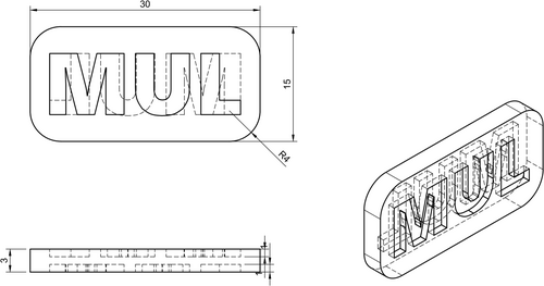
The printing parameters were established by conducting a series of trials to assess the printing performance. At least five samples were printed for debinding testing and to ensure a reliable comparison of the printability of each feedstock system. The geometry for the printing process is shown in Figure 1.
The debinding procedure was evaluated by assessing material loss, changes in geometry, and defects that may have formed during the debinding process. Solvent debinding was performed for five printed parts of each formulation. The debinding process was conducted for 24 h at room temperature. Cyclohexane was used as a solvent for the feedstocks with TPE1, and acetone for the feedstocks with TPE2 as the main component.
2.7 Thermal Debinding and Sintering
As previously mentioned, after selecting the optimal feedstock formulation, initial thermal debinding and sintering tests were conducted using samples made from the AlSi1 alloy. The thermal debinding process was performed under an oxidizing atmosphere (Ar + 3 mol% O2), starting from room temperature and heating to 400°C. A holding time of 120 min at this temperature was employed to eliminate a significant amount of the binder material. The sintering process was then done by increasing the temperature to 630°C at a heating rate of 3 K/min The sintering time at this temperature was set to 60 min for the AlSi1 alloy samples. For the commercial Al6061 alloy tests, the thermal debinding was performed from room temperature up to 480°C with a holding time of 180 min at this temperature. The sintering temperature was set at 630°C. The heating rate during sintering was reduced to allow more time to remove gases and to facilitate the sintering process. It should be noted that for the Al6061 alloy, the thermal debinding and sintering process was done under nitrogen.
3 Results and Discussion
3.1 Feedstock Quality
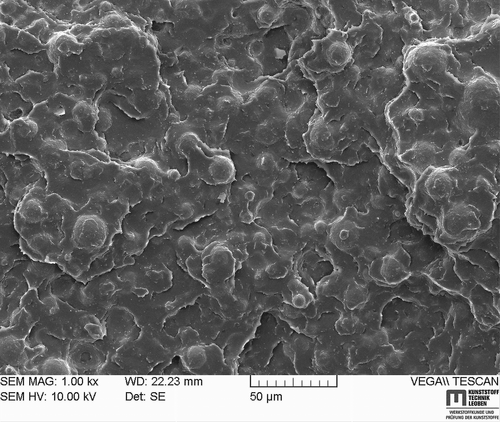
Achieving uniform dispersion of powder particles within the polymer matrix is critical to preventing processing challenges such as viscosity fluctuations and subsequent pressure variations in the nozzle during printing [48-50]. Non-uniform dispersion may lead to inconsistent printing outcomes and, during the solvent debinding step, can result in cracking due to localized binder-rich zones [11]. Therefore, ensuring thorough mixing and uniform dispersion of powder particles in the binder system is essential to maintain process stability and product integrity. Figure 2 shows the SEM of the feedstock sample containing 55 vol% powder loading. The SEM was taken on the feedstock sample after mixing. The binder system demonstrates uniform coverage of the particles for the PP(A)-TPE2-20 feedstock. All feedstock formulations exhibit appropriate mixing behavior and ensure uniform distribution of the binder system among the powder particles.
3.2 Rheological Properties
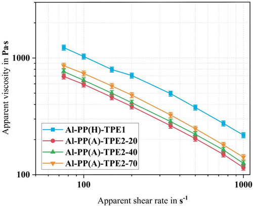
From the rheological assessment, it was observed that all feedstocks exhibit shear-thinning behavior, characterized by a reduction in viscosity with increasing shear rate. This observation underscores the non-Newtonian fluid properties of the materials under investigation. Specifically, the polymer chains within these materials tend to entangle and align in the direction of flow, thereby reducing internal resistance and increasing the flowability (decreasing the viscosity) of the feedstock viscosity.
From Figure 3, it is evident that TPE2 could be more suitable compared with TPE1, as it exhibits lower viscosity across all feedstock formulations. However, the final selection depends on the other parameters here investigated (Sections 3.3, 3.6). The minimal viscosity is observed when employing TPE2 with lower hardness (TPE2-20) in conjunction with PP-g-MA. The differences in the viscosity dependency to shear rate are the difference in the intrinsic viscosity of TPE1 and TPE2. While lower viscosity leads to more flowability and probably more wetting of the particles with the polymer, higher viscosities lead to more shear stress transfer from the binder system to the particles and deagglomeration. Therefore, it is essential to have both flowability and high stress transfer to produce an optimized filament that will further result in better printing behavior and final properties of the part. Therefore, TPE2-40 and TPE2-70 are better suited to fulfill the required rheological behavior compared with TPE2-20.
3.3 Thermal Properties
3.3.1 Differential Scanning Calorimetry (DSC)
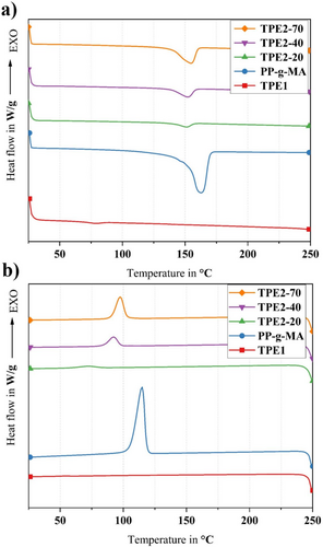
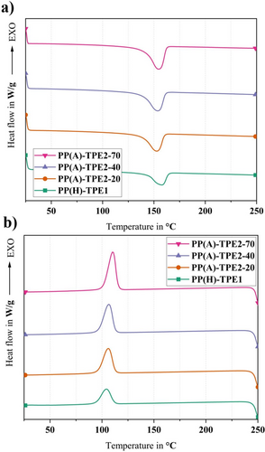
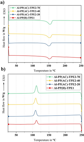
DSC analysis was conducted to investigate the thermal properties and quantify the crystallinity levels. Figures 4-6 show the thermographs of pure polymers, binder systems, and feedstocks, respectively. Table 2 presents the thermophysical properties of pure materials, binder systems, and feedstocks. The melting temperature is denoted as Tm, the crystallization temperature as Tc, the degree of crystallinity as Xc, the enthalpy of melting as ΔHm, and the enthalpy of crystallization as ΔHc.
| Heating | Cooling | ||||
|---|---|---|---|---|---|
| Tm (°C) | ΔHm (J/g) | Tc (°C) | ΔHc (J/g) | Xc (%) | |
| Pure materials | |||||
| PP-g-MA | 162.7 ± 1.2 | −87.4 ± 2.1 | 115.0 ± 1.3 | 94.3 ± 1.1 | 41.8 ± 0.3 |
| TPE1 | 75.1 ± 1.3 | −0.6 ± 0.1 | — | — | — |
| TPE2-20 | 151.0 ± 0.8 | −5.6 ± 0.1 | 72.4 ± 1.0 | 4.8 ± 0.1 | — |
| TPE2-40 | 152.1 ± 0.9 | −13.1 ± 0.2 | 92.4 ± 0.8 | 13.3 ± 0.2 | — |
| TPE2-70 | 154.6 ± 1.0 | −27.0 ± 0.3 | 97.4 ± 0.5 | 27.7 ± 0.2 | — |
| Binder systems | |||||
| PP(H)-TPE1 | 157.5 ± 1.1 | −27.6 ± 0.3 | 104.2 ± 0.7 | 25.1 ± 0.2 | 38.1 ± 0.3 |
| PP(A)-TPE2-20 | 152.7 ± 0.5 | −39.0 ± 0.4 | 106.0 ± 0.9 | 39.4 ± 0.4 | 53.8 ± 0.5 |
| PP(A)-TPE2-40 | 153.7 ± 0.6 | −44.2 ± 0.2 | 106.7 ± 1.0 | 43.6 ± 0.4 | 61.1 ± 0.5 |
| PP(A)-TPE2-70 | 154.6 ± 0.5 | −51.9 ± 0.4 | 110.2 ± 0.9 | 53.1 ± 0.3 | 71.7 ± 0.6 |
| Feedstocks | |||||
| Al-PP(H)-TPE1 | 151.5 ± 0.5 | −5.0 ± 0.1 | 111.7 ± 0.8 | 4.6 ± 0.1 | 33.2 ± 0.4 |
| Al-PP(A)-TPE2-20 | 150.0 ± 0.6 | −7.6 ± 0.1 | 109.1 ± 0.7 | 7.6 ± 0.2 | 49.7 ± 0.3 |
| Al-PP(A)-TPE2-40 | 151.4 ± 0.8 | −8.2 ± 0.1 | 109.6 ± 1.0 | 8.6 ± 0.2 | 54.0 ± 0.4 |
| Al-PP(A)-TPE2-70 | 153.2 ± 1.6 | −9.4 ± 0.2 | 111.9 ± 1.2 | 10.1 ± 0.3 | 61.9 ± 0.6 |
Upon analyzing the melting curves depicted in Figure 4a, distinct melting peaks corresponding to various Shore hardness levels of TPE2 were observed. Specifically, a peak at 151°C was noted for TPE2-20, 152°C for TPE2-40, and 154°C for TPE2-70. These findings indicate that both the melting temperatures and melt enthalpies increase progressively with Shore hardness. This behavior can be attributed to variations in the ratio of soft to hard segments within the microstructure of TPE2, supporting the idea that higher Shore hardness correlates with a greater proportion of hard segments. The differences among the grades of TPE2 are investigated in the following section.
A comparison of the cooling behavior of the pure materials, as shown in Figure 4b, reveals that PP-g-MA exhibited a crystallization peak at 114°C, whereas the crystallization peaks for TPE2-20, TPE2-40, and TPE2-70 were observed at 72°C, 92°C, and 97°C, respectively. Based on the crystallization enthalpies, it can be concluded that as the hardness and the proportion of hard segments in the TPE increase, the proportion of crystalline phases also rises relative to the amorphous phases since the hard segments are crystalline.
A decrease in the melting temperature of PP-g-MA to ~154°C was detected when incorporated with TPE2 into the binder system, while only nominal reduction was observed in the melting temperature of PP-g-MA after the addition of TPE1. The observed shift from 162°C to 154°C indicates that TPE2 likely reduces the thermal barrier for melting of the PP phase in the binder system. Hence, the melting temperature is shifted to lower values, thereby modifying the composite's melting characteristics. However, adding TPE2 and TPE1 resulted in the reduction of the crystallization temperature, meaning that both TPEs hinder or slow down the crystallization process in the PP phase. However, the crystallinity content increases in all binders containing TPE2, which results in increasing melting enthalpies (Table 2). It can be inferred that TPE2 crystals are added to PP crystalline phases, and it resulted in enhancing the crystallinity of the whole binder systems, compared with pure materials.
The PP(H)-TPE1 binder system exhibits a crystallization temperature (Tc) of ~103°C, compared with the Tc of pure PP-g-MA at around 114°C (Figures 4 and 5). The introduction of TPE1 into the PP(H)-TPE1 binder system thus results in a lower crystallization temperature. This suggests that the PP-g-MA chains require a greater reduction in energy to align properly and form a stable crystalline structure. The observed behavior indicates that TPE1 hinders the crystallization, potentially by creating a heterogeneous nucleating environment or by physically obstructing the orderly arrangement of the PP-g-MA chains.
However, in the feedstocks (refer to Table 2), the melting temperature is at ~151.5°C. There was a notable decrease in both melt and crystallization enthalpy compared with pure materials, and a substantial drop in crystallinity, averaging around 12%. This significant reduction in crystallinity compared with the binder system suggests that the metal powder particles in the feedstock act as an inhibitor of crystallization. This inhibition may be due to the interference of the powder with the alignment of polymer chains, thus impeding the formation of organized crystalline structures.
The incorporation of AlSi1 powder into the binder systems has the effect of raising the crystallization temperature to around 111°C. The presence of AlSi1 particles likely can facilitate the nucleation process of the polymer by providing nucleation sites, leading to quicker and more efficient crystallization at higher temperatures. However, the addition of powder to the binder systems results in a reduction of the Tm to around 151°C, down from ~153°C. The decrease in polymer chain mobility is primarily due to the presence of metallic particles, which hinder their ability to align and melt uniformly.
3.3.2 Thermogravimetric Analysis (TGA)
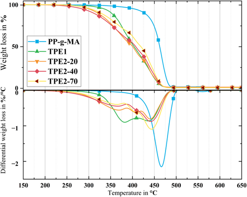
The thermal degradation of binder system components is crucial in the MMEX process for Al alloys, as the initial stages of sintering for these alloys commence at temperatures around 550°C. Most binder polymers degrade when exposed to temperatures close to this range. To assess the degradation temperatures of the components and the feedstock systems, TGA of the pure materials was conducted under nitrogen. The results are depicted in Figure 7 and summarized in Table 3.
| Sample | 1st step | 2nd step | 3rd step | Residue in wt% at 500°C | |||
|---|---|---|---|---|---|---|---|
| T i | T e | T i | T e | T i | T e | ||
| (°C) | |||||||
| PP-g-MA | 466 ± 4 | 493 ± 2 | — | — | — | — | 1.71 ± 0.3 |
| TPE1 | 378 ± 2 | 408 ± 4 | 442 ± 4 | 488 ± 3 | — | — | 1.14 ± 0.2 |
| TPE2-20 | 370 ± 3 | 393 ± 3 | 406 ± 1 | 423 ± 4 | 438 ± 2 | 488 ± 1 | 1.40 ± 0.1 |
| TPE2-40 | 372 ± 3 | 393 ± 3 | 408 ± 1 | 417 ± 2 | 436 ± 1 | 487 ± 2 | 0.95 ± 0.1 |
| TPE2-70 | 369 ± 1 | 386 ± 3 | 407 ± 1 | 416 ± 1 | 448 ± 1 | 488 ± 2 | 0.73 ± 0.1 |
The TGA and dTGA analyses provided the degradation temperatures (Ti and Te) and degradation rates for pure materials. The dTGA curves for the backbone displayed a distinct single peak, indicating a singular predominant degradation mechanism. It is important to note that the TGA was conducted under a nitrogen atmosphere, while the thermal debinding will partially occur in an oxygen atmosphere, leading to an earlier onset of degradation [24, 51]. However, controlling the residual oxygen content could be very challenging by using an oxidizing debinding atmosphere. Although most of the TPE could be removed during solvent debinding, investigating the TGA of feedstocks including TPE still is crucial. The reason for that is complete removal of all TPE during solvent debinding is not required, and typically some TPE residue remains, which should be eliminated during the thermal debinding process [52].
The investigation of the remaining mass at a temperature of 500°C yielded additional information regarding the stability and degradation properties of these polymers. The existence of an excessive amount of carbonaceous residues has the potential to impede the quality of sintering, which in turn can have an impact on the mechanical characteristics and structural integrity of the end product [53, 54]. Also, it can affect the properties/quality of the sample even when full sintering occurs, for example, by the formation of secondary phases which lower the ductility of the material [55, 56].
In comparing the thermal degradation properties of the main components (TPE2-20, TPE2-40, TPE2-70, and TPE1), TPE1 exhibits a degradation process comprising two distinct steps. The first stage occurs at 378°C, while the second step occurs at 442°C. It may be concluded that this pattern suggests a complex degradation mechanism involving multiple components or phases within the polymer. Additionally, each variant of TPE2 displayed three identifiable degradation peaks. These peaks were consistently observed across different hardness grades of the material within a specific temperature range. The initial degradation peak occurred at 370°C, followed by subsequent peaks at 407°C and 440°C. The sharpness of the third peak indicates it as the primary degradation mechanism for all three TPE2 variants. This phenomenon can be attributed to the chemical structure of TPE2, particularly the different temperatures at which its soft and hard segments degrade.
Different types of TPE2 exhibited a relationship where higher shore hardness correlated with lower residue formation. Specifically, TPE2-70, the most rigid variant in the series, had the lowest residue at 0.74 wt%. In contrast, TPE2-40 and TPE2-20 had higher residue levels, at 0.95 and 1.40 wt%, respectively. This is mainly due to the different formulation of TPE2s containing various inorganic additives in different proportions.
To provide a clearer understanding of the impact of metal particle inclusion on the thermal properties of the binder system, TGA curves were used to evaluate the feedstocks, and the results are summarized in Table 4. Notably, all feedstock systems displayed a two-phase degradation curve. This is primarily due to the binder system comprising two components, each with distinct degradation characteristics. This effect, illustrated in the TGA curves (Figure 8), was particularly evident in the feedstock systems containing TPE2. The TGA and dTGA curves of Al-PP(A) incorporating TPE2 as the primary binder demonstrate significant alterations in degradation characteristics compared with the pure TPE2 TGA and dTGA curves. Unlike the typical three-peak degradation pattern observed in pure TPE2, the TGA and dTGA curves for Al-PP(A) feedstock exhibit only two major degradation peaks.
| Sample | 1st step | 2nd step | ||
|---|---|---|---|---|
| T i | T e | T i | T e | |
| (°C) | ||||
| Al-PP(H)-TPE1 | 386 ± 3 | 396 ± 3 | 447 ± 3 | 490 ± 2 |
| Al-PP(A)-TPE2-20 | 344 ± 2 | 389 ± 3 | 453 ± 4 | 491 ± 4 |
| Al-PP(A)-TPE2-40 | 344 ± 1 | 393 ± 3 | 455 ± 3 | 493 ± 1 |
| Al-PP(A)-TPE2-70 | 356 ± 2 | 366 ± 2 | 458 ± 1 | 494 ± 2 |
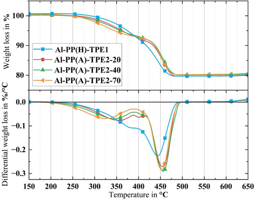
The enhanced thermal conductivity of the metal particles facilitates faster heat transfer within the feedstock, thereby influencing its degradation kinetics. This shift is most pronounced at the first peak, indicating the presence of Al particles in the TPE2 phase. Moreover, the intensity of the peaks in the dTGA curves suggests that the main degradation process for these feedstocks predominantly occurs at the second peak, due to the PP, which produces high peaks in this temperature range.
As it was mentioned, one of the challenges in developing feedstock for Al is having a low sintering temperature compared with other metals and ceramics. Since pre-sintering and sintering steps for Al alloy occur within the 500°C–600°C range, it is crucial to ensure the complete removal of the binder system at temperatures below 500°C [25]. In conclusion, the TGA curves of the feedstocks reveal that all feedstock formulations exhibit an acceptable range of thermal degradation temperatures for the MEX process of Al feedstock since they all degrade at temperatures lower than 500°C.
3.4 Evaluation of the Contact Angle
Table 5 presents the surface energy and contact angle values with deionized water (θw) for each component of the different binder systems. A lower contact angle with deionized water, a polar liquid, correlates with enhanced wettability. Effective surface wetting facilitates the better distribution of powder particles throughout the binder system, which is crucial for producing homogeneous feedstock materials.
| Components | Contact angle in ° | Surface energy in mN/m | |||
|---|---|---|---|---|---|
| θ w | θ D | σ D | σ P | σ T | |
| PP-g-MA | 109.10 ± 3.00 | 51.10 ± 4.96 | 33.66 | 0.13 | 33.79 |
| TPE1 | 101.40 ± 2.33 | 56.00 ± 3.93 | 30.87 | 0.21 | 31.08 |
| TPE2-20 | 114.20 ± 2.19 | 66.20 ± 3.15 | 25.02 | 0.07 | 25.09 |
| TPE2-40 | 111.10 ± 2.77 | 66.70 ± 4.56 | 24.73 | 0.00 | 24.73 |
| TPE2-70 | 108.40 ± 1.70 | 64.60 ± 4.41 | 25.93 | 0.03 | 25.95 |
The primary binder materials exhibit hydrophobic properties, as evidenced by a contact angle exceeding 90° and a significantly reduced polar component. This suggests a low tendency to form bonds with polar substances, potentially affecting their ability to spread and adhere to surfaces in environments where polar substances are prevalent. This also indicates that it might be hard for TPE1 and TPE2 to be dissolved in acetone, which is a polar solvent. This is investigated further in the following sections.
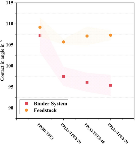
Figure 9 illustrates the averaged contact angle values for the binder systems and feedstocks. It is apparent that the feedstocks generally exhibit higher contact angles compared with their respective binder system formulations. Notably, the binder systems with various types of TPE2 as the main component (PP(A)-TPE2) have lower contact angles. However, a significant difference is observed when TPE1 is used as the main component: the PP(H)-TPE1 binder system exhibits a higher contact angle than the PP(A)TPE2 binder systems, and this disparity becomes even more pronounced when considering the feedstocks. Considering the contact angles of the feedstocks, it can be inferred that feedstocks containing TPE2 will demonstrate superior processability and printing performance, a hypothesis that will be further examined in Section 3.6.
3.5 Fourier-Transform Infrared Spectroscopy
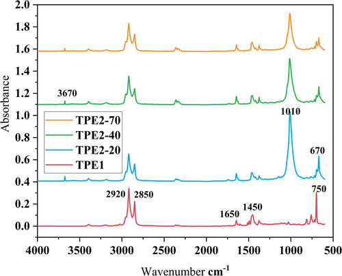
The results of FTIR are presented in Figure 10. The characteristic peaks for TPE1 are the out-of-plane bending vibrations of C–H groups at 700–810 cm−1. These peaks are also present in TPE2s, but they are smaller. However, the sharp peak at 670 cm−1 for TPE2s could be associated with vibrations in Si–O bonds (from additives) or other inorganic components in the material. The peak at 1450 cm−1 indicates C–H bending vibrations of CH2 or CH3 groups, typical of aliphatic hydrocarbons in thermoplastics, and 1650 cm−1 likely corresponds to C=O stretching from carbonyl groups, which can be present in oxidized components or additives. Peaks at 2800–3000 cm−1 are C–H stretching, with the peak at 2920 cm−1 corresponding to asymmetric stretching of CH2 groups and the peak at 2850 cm−1 corresponding to symmetric stretching of CH2 groups. These peaks indicate the presence of aliphatic hydrocarbons in the polymer backbone. For TPE2s, the sharp peak at 1010 cm−1 is indicative of C–O–C stretching vibrations, often associated with ether or ester groups in thermoplastics or additives, which is reducing by increasing the hardness in the sample, showing that the elastomeric phase of TPE2 contains these groups. The peak at 3670 cm−1 likely corresponds to isolated O–H stretching vibrations from free hydroxyl groups, possibly present in the material or from specific additives. These hydroxyl groups are not hydrogen-bonded, which explains the sharpness of the peak. The spectrum suggests a combination of aliphatic hydrocarbons, possible hydroxyl groups, and structural features of potential additives. The peaks at 2920, 2850, and 1450 cm−1 confirm the presence of aliphatic hydrocarbons, typical for TPE or similar polymers. The peaks below 1010 cm−1 suggest structural details (e.g., filler materials or aromatic components) that complement the polymer matrix. Therefore, TPE1 is mainly an aliphatic polymer that is soluble in nonpolar solvents like cyclohexane. The TPE2s may also be soluble in polar solvents like acetone due to the possible presence of ether and ester groups. The purpose behind choosing acetone is that acetone has a dipole moment of 2.88 D [57], which makes acetone capable of dissolving both polar and some nonpolar substances (polar aprotic solvent).
3.6 Printing Performance
After initial trials, a printing temperature of 255°C, a bed temperature of 100°C, a layer height of 0.2 mm, and a printing speed of 10 mm/s were chosen for the printing process. Following initial trials, an extrusion multiplier of 110% was implemented in the printing process to mitigate under-extrusion problems due to filament variability fluctuations [58].
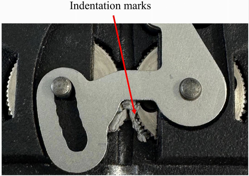
The printing of Al-PP(A)-TPE2-20, which incorporates the TPE with the lowest hardness (Shore A 20), proved challenging due to clogging. The filament exhibited insufficient rigidity for proper extrusion, resulting in it being compressed between the gears during the extrusion process. Figure 11 shows the indentation marks left by the gears in the soft filament.
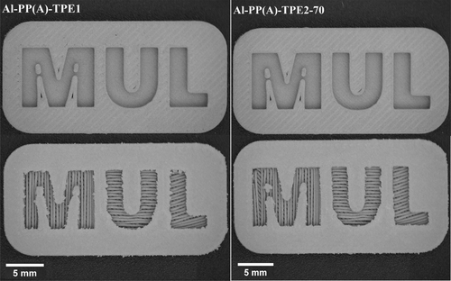
Although printing of the Al-PP(A)-TPE2-40 samples was feasible, adhesion of the printed parts to the bed presented challenges during part removal. This problem could not be solved by varying the bed temperature (30°C, 50°C, and 100°C). Due to the softness of the printed parts, applying excessive force to remove them from the bed risked causing warpage. Figure 12 illustrates the top and bottom of the printed parts for Al-PP(A)-TPE1 and Al-PP(A)-TPE2-70, both of which were successfully printed without any issues. However, the handling and spooling of Al-PP(A)-TPE2-70 demonstrated some challenges due to the low filament flexibility, though it was manageable. From the perspective of filament production and printing performance, it is advisable to increase the backbone content in Al-PP(A)-TPE2-70 while reducing the percentage of TPE2-70 in the binder system.
3.7 Solvent Debinding
Figure 13 gives the mean values of TPE removal during solvent debinding. It is important to note that after 24 h of solvent debinding at room temperature using acetone for TPE1, a mass loss of ~5 wt% was observed. Therefore, when TPE1 is the primary component, cyclohexane was used, whereas acetone was employed for samples containing TPE2, both at room temperature for 24 h. The ratio of solvent to feedstock was 20 mL/g. Also, it should be noted that the PP used in this study was insoluble in both solvents according to experiments [17]. The results highlight a notable difference in solubility between TPE1 in cyclohexane and TPE2 in acetone. Solvent debinding of the Al-PP(H)-TPE1 feedstock system in cyclohexane leads to the removal of > 90 wt% of TPE1, which is a satisfactory performance. This leads to a porosity of around 27% in the material by considering a 45 vol% binder system in the feedstock and a 65 vol% TPE1 in the binder system. It is evident that increasing the hardness of different types of TPE2 decreases their solubility in acetone. Specifically, for the Al-PP(A)-TPE2-20 feedstock, < 40 wt% of TPE2-20 is removed, indicating that solvent debinding with acetone is not suitable for formulations with TPE2.
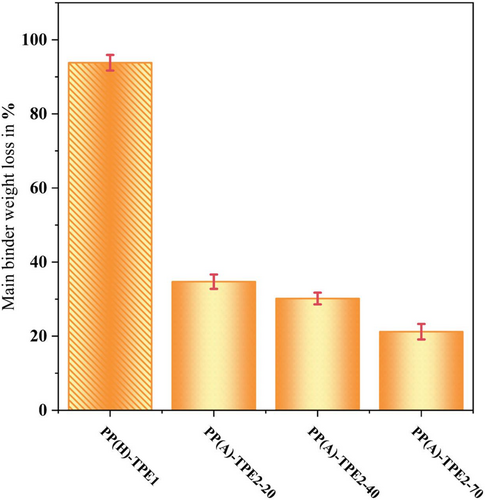
Effective removal of the main component during solvent debinding reduces the amount of organic material that must be removed during thermal debinding, thus facilitating low residual carbon and oxygen levels in the sintered material. Effective solvent debinding also creates an open-porous structure before thermal debinding, which facilitates faster removal of the gaseous decomposition products of the backbone material. Due to the higher solubility of TPE2-20 in acetone, the solubility of this grade in acetone at 60°C was also tested. After 24 h, ~60 wt% of the TPE2-20 was removed, which remains lower compared with the TPE1. However, it should be noted that the samples in acetone retained the shape after solvent debinding. While TPE2 is soluble in cyclohexane, its use does not accomplish the objective of the study to develop a binder system suitable for solvent debinding in acetone.
3.8 Thermal Debinding and Sintering
Regarding the printability and solvent debinding trials conducted with various feedstock formulations made from AlSi1 powder, only the Al-PP(H)-TPE1 feedstock showed promising results. As a result, it was selected for further thermal debinding and sintering trials.
In pressureless sintering of AlSi1 parts, densification occurs through liquid phase sintering. However, this alloy has a narrow melting range, which means that minor temperature variations can significantly affect the sintering behavior. These fluctuations can lead to the formation of melt beads and their subsequent escape during the sintering process (see Figure 14).
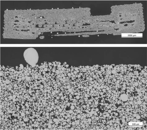
Despite these challenges, the measurements provided valuable insights into optimizing the thermal treatment. The larger residual voids observed (Figure 14) were mainly due to the insufficient escape of gases generated during decomposition. Furthermore, the results indicated that the AlSi1 samples retained a high carbon content of 2.7% after sintering, which may negatively impact the sintering process.
Based on the experience gained from sintering trials involving AlSi1, the thermal debinding process for feedstocks containing Al6061 powder was modified. The modifications included extended holding times and reduced heating rates during the thermal debinding stage. These adjustments were specifically designed to facilitate the more effective removal of gases produced during the process, thereby improving carbon removal.
Additionally, to minimize oxygen exposure, the thermal debinding of samples containing Al6061 powder was conducted in a nitrogen environment. Unlike the AlSi1 samples, no melt beads formed on the surface of the Al6061 samples. This absence of melt beads is likely due to the better regulation of melt content, which is made easier by the wider melting range of the Al6061 alloy. As a result, this leads to sintered parts with acceptable visual quality (see Figure 15a).
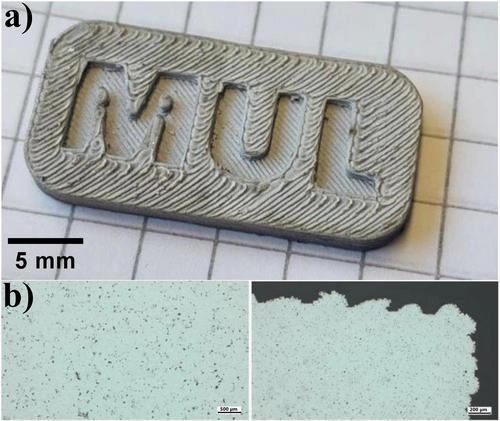
As shown in Figure 15b, the samples produced with the Al6061-PP(H)-TPE1 feedstock formulation achieved near-complete densification during sintering, in contrast to the AlSi1 samples. Chemical analyses of these samples indicated oxygen levels of ~0.25% and carbon levels around 0.1%. Therefore, it has been demonstrated that utilizing the binder system PP(H)-TPE1 with Al6061 allows for the production of parts with lower porosity and reduced residual carbon and oxygen concentrations.
4 Conclusions
This study investigated the development of a binder system incorporating TPE2 as the primary component, which is soluble in less harsh solvents such as acetone according to the supplier. Three TPE2 variants with hardness values of 20, 40, and 70 Shore A were examined in comparison with a TPE1 soluble in cyclohexane. From a rheological perspective, the feedstocks containing TPE2 have lower viscosity at various shear rates, which may suggest their suitability for the MMEX process. DSC analysis revealed a reduction in crystallinity in the feedstocks compared with the binder systems, likely due to the interference of the powder with the alignment of the polymer chains. While the feedstock with TPE1 displayed lower crystallinity than those containing TPE2-20 and TPE2-40, parts produced from feedstocks containing TPE1 and TPE2-70 did not experience warpage post-printing, even though TPE2-70 was more crystalline. This indicates that the hardness of the soluble component in the binder system plays a critical role in printability, but it cannot directly be linked to the degree of crystallinity.
TGA demonstrated that all feedstocks exhibited acceptable thermal degradation temperatures for use in aluminum-based feedstocks. Regarding contact angle and printability, while it is well established that a lower contact angle can improve processability and printing performance, the mechanical properties of TPE have a more significant influence on printing outcomes in this investigation. A contact angle range of 95°–109° appears to be sufficient for a successful MEX process. Furthermore, the results indicated that TPE2 with a hardness below 40 Shore A (TPE2-20 and TPE2-40) is unsuitable as the primary component in feedstock formulations, as it leads to clogging and warpage during or after printing due to insufficient rigidity.
Solvent debinding experiments showed that up to 60 vol% of TPE2-20 in the feedstock can be removed by solvent debinding in acetone at 60°C, but solubility remained insufficient to ensure an effective subsequent thermal debinding process. Since acetone proved ineffective, other solvents should be investigated, and further thermal debinding and sintering trials were performed with the binder system soluble in cyclohexane containing TPE1. The thermal debinding and sintering processes posed significant challenges for the feedstock with AlSi1 due to its limited melting range. In contrast, the chosen feedstock, composed of Al6061 alloy (Al-PP(H)-TPE1), was successfully subjected to thermal debinding and sintering under a nitrogen atmosphere.
These findings contribute valuable insights into the formulation of binder systems for the MEX process, emphasizing the importance of TPE hardness and solvent interactions in determining the performance and quality of printed parts.
Acknowledgments
Open access funding provided by Montanuniversitat Leoben/KEMÖ.
Conflicts of Interest
The authors declare no conflicts of interest.
Open Research
Data Availability Statement
The data that support the findings of this study are available from the corresponding author upon reasonable request.


