The effect of concomitant gradient fields on MRI with long readout radial-based trajectories
Abstract
Purpose
To demonstrate in theory and practice that concomitant gradient fields (CCGF) can produce substantial imaging artifacts in scans utilizing radial-based trajectories and to provide strategies to mitigate these effects.
Theory and Methods
A framework was developed to relate concomitant gradient phase to local point-spread-function distortion, which was used to evaluate the effects of trajectory choice and imaging parameters on imaging artifacts. Gradient waveforms for realistic imaging scenarios were simulated and used to determine the effect of CCGF. Phantom and in vivo experiments were performed at 3 T to validate theoretical predictions.
Results
CCGF-induced artifacts are shown to be produced in part by increased variation in concomitant gradient phase across view angles. This is shown to increase with increasing gradient strength and contrast index in radial-based trajectories. Phase variation across view angles and the associated artifacts are shown to be effectively diminished via azimuthal rotation down the echo train in the helical EPI and helical stack-of-stars trajectories introduced in this work.
Conclusions
Concomitant gradient fields are found to produce non-negligible imaging artifacts in long readout radial-based trajectories due to variations in the associated phase accrual across view angles. Azimuthal rotation of the readout direction down the echo train, as implemented in the helical EPI and helical stack-of-stars trajectories, is shown in simulations, phantoms, and in vivo to mitigate these effects. Substantial improvement is seen in cases of nonaxial imaging with multiple contrasts, quickly varying B0 inhomogeneity, and/or high gradient amplitudes.
1 INTRODUCTION
Fundamental to signal localization in MRI is a precise knowledge of the local magnetic field strength at each given point in space. The use of linear gradients in the primary static magnetic field (Bz) allows the signal localization problem to be simplified to an inverse Fourier transform of the signal. However, the Maxwell equations dictate that when gradients in Bz are employed within the MRI scanner, there will necessarily be additional gradient fields orthogonal to Bz that are produced simultaneously with the gradients in Bz and that change the local magnetic field at any given point in space. The behavior of these fields, often termed concomitant gradient fields (CCGF), has been well described by Bernstein et al.1 The spatially variant perturbations of the magnetic field due to CCGF give rise to distortions of the magnitude and phase of the resulting complex image data. These distortions vary in magnitude and appearance with different gradient timings, amplitudes, and k-space trajectories. Additionally, it is well known that the magnitude of the CCGF distortions increases as the main magnetic field strength decreases, and thus low-field imaging situations in general have more egregious CCGF-based artifacts.1-3
Within high-field situations, long readout trajectories are particularly prone to the effects of CCGF. Because of this, much work has been done in the analysis of the behavior of CCGF and corrections for their effects in Cartesian EPI trajectories4, 5 and spirals6, 7 in gradient echo imaging as well as in steady-state free precession sequences8 and fast spin-echo sequences.9, 10 The effects of CCGF are distinctly different in style for these trajectories and even can vary based on the orientation of the imaging plane. Reconstruction methods for these have been proposed and implemented that seem to correct for some of the effects of CCGF in these trajectories, such as conjugate phase reconstruction and its faster derivates11, 12 or regional phase corrections.5 However, comparatively little has been done to analyze and correct for CCGF effects in radial-based trajectories, with existing work focusing on corrections to phase images.13 Several versions of long readout radial-based trajectories have been developed recently, including the hybrid radial-Cartesian trajectories of radial kz-blipped 3D gradient echo EPI for whole-brain perfusion (RAZER),14 trajectory using radially batched internal navigator echoes (TURBINE),15 stack-of-stars k-space trajectory with EPI planes (SOS-EPI),16 and others.17, 18 In 2022, Rettenmeier et al. developed a single contrast rotating version of these in 3D radial EPI (REPI)19 to improve the temporal stability of the signal with the improved utilization of all k-space dimensions during acquisition. However, all these works only attempted single-contrast acquisitions, or a single echo train per TR, and none evaluated the effects of CCGF on image quality.
A prerequisite to the expansion of the usefulness of these and similar trajectories in MRI is a greater understanding of their underlying physics and knowledge of strategies to mitigate or correct for CCGF effects therein. In this work, we seek to elucidate the particular challenges of long readout multi-contrast radial trajectories with respect to CCGF and introduce helical EPI (HEPI) and helical stack-of-stars (HSOS) as trajectories that mitigate these challenges.
2 THEORY
Equation (7) indicates that the effect of CCGF can be modeled as a sum of many spatially invariant, but potentially different, convolutions of the object with a point spread function (PSF). This PSF encapsulates both the sampling pattern and the associated accrued phase from CCGF. Of note, this same equation results if B0 inhomogeneity is added so long as the piecewise constant nature of this extra phase term is maintained. The derivation with B0 inhomogeneity is included in the Appendix.
By using Equations (3) and (4) with knowledge of the gradient waveforms for a given trajectory, the concomitant gradient phase for each k-space sample can be determined. After gridding these samples for non-Cartesian trajectories, an inverse Fourier transform can be applied to give PSFv (Equation 8). This notion of a voxel-dependent PSF can conveniently describe and predict CCGF-based distortion and ghosting phenomena that have been previously discussed in literature for Cartesian EPI trajectories4, 5 and fast spin-echo imaging.10 The closer this PSF comes to approximating a Dirac delta function, the less artifactual the resulting magnitude and phase images will be. As will be demonstrated in the results, nonuniformity of the concomitant gradient phase across k-space points can have a strong impact on the resulting PSF.
2.1 Variations in concomitant gradient phase
Radial-based trajectories are plagued with an additional problem not generally faced in Cartesian or spiraling trajectories (except in cases with large rewinder or phase encoding gradients), which is that the CCGF associated with these trajectories do not just vary spatially but can also vary substantially across TRs due to the differing amplitudes of the readout gradients across radial views. Thus, the phase accrual over one radial view can occur at a different rate than the phase accrual over a different view. When there are large variations in the phase for different view angles, the result is a distorted PSF and signal loss, both of which negatively impact image quality. As will be shown in the results, fast multi-contrast sequences are especially plagued by this issue due to their higher gradient amplitudes. We now consider the effect of varying the direction of readout gradients within different imaging orientations. The following analysis is specific to those artifacts caused by concomitant gradient phase variation across radial views as opposed to other forms of CCGF-induced artifacts, such as banding in bSSFP.8
2.1.1 Axial (transverse) imaging
In axial imaging with a radial acquisition, the x and y physical gradients are utilized for readout. For radial trajectories, the total readout gradient strength is constant at ; thus, the first term of Equation (4) remains constant across radial views for a given plane, with the other terms contributing minimally to the overall concomitant gradient phase. Therefore, axial images acquired near isocenter will have little to no warping of the PSF in-plane. Blipped-kz trajectories such as RAZER,14 TURBINE,15 REPI,19 or HEPI will additionally have to consider the slight radial through-plane PSF distortion arising from those kz blips, as indicated by the second term of Equation (4).
2.1.2 Coronal and sagittal imaging
In coronal imaging with a radial acquisition, the x and z physical gradients are utilized for readout. In this case, the first term of Equation (4) is no longer constant, and the second and third terms are no longer negligible as they are in axial imaging, resulting in potentially large variations in phase with azimuthal view angle. Due to the extra division by 4 in the x direction, the warping of the PSF will be substantially more severe along the z-direction. In sagittal imaging with a radial acquisition, CCGF effects are the same as in coronal imaging, with the x dimension replaced by y.
2.1.3 Oblique imaging
For oblique imaging planes, the x, y, and z physical gradients may be employed simultaneously during each readout. However, as shown by Equation (4), the x and y gradients contribute equivalently to CCGF, and thus rotations of any given arbitrary scan plane about the physical z axis will not change the CCGF-induced phase variation between radial views. This explains the coronal–sagittal equivalence mentioned above. In addition, scans in oblique planes that involve a nutation about the x or y axes away from the coronal or sagittal planes (which thereby come into closer alignment with the transverse plane), will necessarily have decreased CCGF-induced phase variation between radial views relative to scans in the coronal and sagittal planes due to the decrease in the relative amplitude of the z gradient compared to the x and y gradients. Further decreases in the utilization of the z gradient in readout will continue to decrease this CCGF-induced phase variation.
2.2 Mitigating CCGF-based artifacts in radial imaging
CCGF-based artifacts can be minimized by limiting the variation of accrued phase across view angles. This can be accomplished in at least two ways. The most straightforward method is to limit the gradient amplitude at the expense of resolution and speed. However, this may be unacceptable in some cases, such as in high-resolution dynamic imaging. When the gradient magnitudes cannot be reduced, phase nonuniformity can be minimized by limiting the variation of the rate of concomitant gradient phase accrual across all TRs.
The variation of concomitant gradient phase across TRs can be decreased by rotating the imaging plane between each readout such that each successive readout is acquired along a different view angle. The gradients associated with a particular view direction for a given protocol will have a specific rate of concomitant gradient phase accrual. As this view direction changes between echoes (along the echo train for hybrid radial-Cartesian EPI, or between image echoes in SOS acquisitions), the relative gradient amplitudes and the associated rate of concomitant gradient phase accrual within that TR are subject to change according to Equation 4. If this rotation of the imaging plane is sufficiently large between each readout, the result will be an approximately constant rate of concomitant gradient phase accrual regardless of the starting view angle.
Rettenmeier et al. performed an azimuthal rotation similar to this with REPI,19 though for their application only small rotations between readout lines were deemed practical. As will be shown in the Results, larger rotations are needed to more fully suppress CCGF-based artifacts from radial-based sequences to thereby enable high-quality multi-contrast acquisitions with these trajectories.
3 METHODS
3.1 Pulse Sequence Design
We implemented a multi-contrast, segmented (multi-shot) 3D pseudo-golden angle (view increment = (1–233/377) × 180° ≈ 68.7533°) version of a hybrid radial-Cartesian EPI trajectory similar to RAZER14 and TURBINE15 on a 3 T scanner (Siemens Magnetom Prisma Fit, Siemens Healthineers, Erlangen, Germany). We will refer to this sequence as SOS-EPI after Jonathan et al.16 due to the trajectory's similarity to its component names. In this sequence, an EPI readout is played out with the phase encoding blips down the logical kz-direction, and the entire EPI plane is rotated about the logical kz axis to read out the next radial view at a new azimuthal angle in the logical kx-ky plane.
To mitigate the effects of CCGF determined in our preliminary studies, we also implemented a rotating version of this sequence that acquires data at view angles that increase linearly by a fixed increment down the echo train. The result is HEPI. The magnetization is prepared for each new view angle by the addition of gradient blips in the logical kx-ky plane that play simultaneously with the phase encoding blips in the logical kz direction. The constancy of the azimuthal angle increment across the view dimension maintains the constancy of the data density within each logical kx-ky plane, thereby simplifying the gridding process. The angle increment between readouts within the echo train, φ, is set to , where ETL is the echo train length, n is an integer in [1, ETL-1], and n and ETL do not share a common prime factor. Figure 1 visually explains this trajectory. For brevity, HEPI-φ will refer to HEPI with an angle increment of φ.

To demonstrate and mitigate CCGF effects in multi-contrast SOS imaging as well, we implemented a rotating-gradient version of that sequence, which we distinguish as HSOS. Similarly to HEPI, HSOS was accomplished via azimuthal rotation blips between readouts, and HSOS-φ will refer to HSOS with an angle increment of φ.
3.2 Simulations
To determine the effects of CCGF on PSFv with radial sampling trajectories, we simulated the gradient waveforms for SOS-EPI and HEPI sequences in the coronal, sagittal, and axial orientations with the parameters given in Table 1 (Integrated Development Environment for Applications (pulse sequence development environment), Siemens Healthineers). These trajectories were then analyzed in MATLAB (R2022b, MathWorks, Natick, MA) using Equations (3) and (4) to obtain the accrued phase () due to CCGF for each radial view across time.
| Parameter | Value |
|---|---|
| Trajectories | SOS-EPI, HEPI |
| Inter-echo azimuthal rotation angle | 0° (SOS-EPI); 25.7°, 51.4°, 77.1° (HEPI) |
| FOV (mm3) | [258 × 258 × 54] |
| Resolution (mm3) | [1.5 x 1.5 x 1.5] |
| No. contrasts | 3 |
| EPI factor | 7 |
| Bandwidth range (Hz/pixel) | [930, 2298] |
- Abbreviations: HEPI, helical echo-planar imaging; SOS-EPI, stack-of-stars EPI.
To make clear the relative variations in the phase across view angle, the mean concomitant gradient phase through time was subtracted from each trajectory's dataset, and the results were averaged across the time points corresponding to each contrast. The original concomitant gradient phase data were then density-compensated21 and gridded,22-24 and a Fourier transform was applied to obtain PSFv. This calculation was repeated across coronal, sagittal, and axial orientations for various gradient strengths and at 32 mm increments in-plane across the FOV for each trajectory type.
3.3 Experiments
All experiments were performed on a 3 T scanner with a 32-channel spine coil and/or a 20-channel head and neck coil. All image reconstruction was performed offline in MATLAB (R2022b, MathWorks) using zeroth- and first-order phase correction,14, 25 density compensation,21 and gridding of the data,22-24 followed by a 3D fast Fourier transform.
3.3.1 Phantom Experiments
To show the validity of our spatially variant PSF formalism, we 3D-printed a custom square-profile phantom with a size of 230 × 230 × 35 mm. Eighty-one 2 mL vials of approximately 10 mm diameter were inserted into the top in a grid pattern, with the spacing of the vials at approximately 25 mm. Each of the vials was filled with 0.75% w/v agar doped to 6–7 mM copper sulfate (CuSO4). The space around the vials was filled with 0.75% w/v agar doped to ˜2.5–3 mM manganese(II) chloride (MnCl2) to produce a very short T2. After the agar had set, the phantom was placed on the 32-channel spine coil and centered in the magnet in the x and z directions. Imaging was performed with SOS-EPI, HEPI, SOS, and HSOS trajectories in the coronal orientation. Further relevant scan parameters are given in Table 2.
| Parameter | Value | ||||
|---|---|---|---|---|---|
| Figure 4 | Figure 5 | Figure 6 | Figure 7 | Figure 8 | |
| Trajectories | SOS-EPI, HEPI, SOS, HSOS | SOS-EPI, HEPI, EPI | SOS-EPI, HEPI, SOS | SOS, HSOS | SOS-EPI, HEPI, SOS, HSOS |
| Inter-echo azimuthal rotation anglea | 36° (HEPI, HSOS) | 36° (HEPI) | 36° (HEPI) | 36° (HSOS) | ˜41.5° (HEPI); 42° (HSOS) |
| FOV (mm3) | [256 × 256 × 16] | [224 × 224 × 32] | [224 × 224 × 32] | [224 × 224 × 28] | [224 × 224 × 52] |
| Orientation | Coronal | Coronal, Axial | Coronal | Coronal | Sagittal |
| Resolution (mm3) | [1.0 × 1.0 × 1.0] | [1.0 × 1.0 × 2.0] | [1.0 × 1.0 × 2.0] | [1.0 × 1.0 × 2.0] | [1.0 × 1.0 × 2.0] |
| No. contrasts | 3 (SOS-EPI, HEPI); 15 (SOS, HSOS) | 3 | 3 | 21 (multi-echo); 1 (single-echo) | 3 (SOS-EPI, HEPI); 12 (SOS, HSOS) |
| EPI factor | 5 (SOS-EPI, HEPI) | 5 | 5 (SOS-EPI, HEPI) | – | 13 (SOS-EPI, HEPI) |
| Bandwidth range (Hz/pixel) | 1396 | 1014 | [532, 1396] | 1014 | 1396 |
| No. radial views | 377 | 377 | 377 | 377 | 377 |
| TR (ms) | 60 (SOS-EPI, HEPI); 35 (SOS, HSOS) | 50 | 50 | 50 | 80 (SOS-EPI, HEPI); 26 (SOS, HSOS) |
| TE (ms) | [6.30 13.91 21.52] (SOS-EPI, HEPI); 3.26 + 1.52n, n [0 14] (SOS, HSOS) | [9.0, 21.06, 33.12] (SOS-EPI); [9.0, 21.6, 34.2] (HEPI, EPI) | [9.0, 21.6, 34.2]b | 1.70 + 1.63n, n [0 20] (multi-echo); 34.3 ms (single-echo) | [13 34 55] (SOS-EPI, HEPI); 1.86 + 1.74n, n [0 11] (SOS, HSOS) |
- Abbreviation: HSOS, helical stack-of-stars.
- a Inter-echo azimuthal rotation angle only applicable for HEPI and HSOS trajectories.
- b TEs for later contrasts in SOS-EPI varied slightly with changes in bandwidth. TE = [9.0, 20.52–21.60, 32.04–34.2] ms.
To demonstrate CCGF-induced artifacts in fast, long-readout radial trajectories, we performed additional phantom scans using (1) a grid phantom, and (2) an Essential System Phantom (CaliberMRI, Boulder, CO). SOS-EPI and HEPI data were acquired in coronal and transversal orientations at various readout bandwidths. SOS and HSOS data were also acquired in single-echo and multi-echo scans at isocenter and at z = 50 mm. Parameters for the phantom scans are given in Table 2. After image reconstruction, the artifact level was compared qualitatively between images acquired using each of these parameter sets, with a SOS or Cartesian EPI scan used as reference. The weighted mean absolute percentage error (wMAPE), which weights the mean absolute percentage error by the absolute value of the reference data, was then used as a quantitative metric of image quality relative to Cartesian EPI.
3.3.2 In vivo experiment
To demonstrate the impact of CCGF in vivo, sagittal brain images were obtained with SOS-EPI, HEPI, SOS, and HSOS trajectories. Experiments were performed in a healthy volunteer after informed consent and with approval from the local institutional review board. Results were qualitatively compared for image quality. Relevant scan parameters are given in Table 2.
4 RESULTS
Instead of attempting to view the concomitant gradient phase of all spatial locations together, it is instructive to look at that of a single spatial location and its associated effect. In this case, the spatial location is fixed, but the slope of the concomitant gradient phase with time for this given point can potentially change with the readout view angle as indicated by Equations (3) and (4). An example of this is shown in Figure 2. The maximum and minimum concomitant gradient phase is plotted across a single TR for SOS-EPI and for HEPI trajectories for the position [x, y, z] = [−128, 0, −128] mm and bandwidth per pixel = 2170 Hz. Other parameters not listed are given in Table 1.
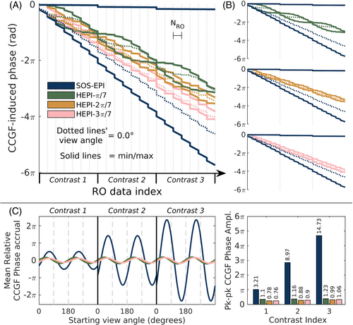
As shown in Figure 2, whereas the phase variation between radial views increases with time and contrast number in SOS-EPI, this phase variation is reduced with rotation of the view angle down the echo train as in the HEPI trajectories. Notably, the concomitant gradient phase for every view in the HEPI trajectories converges to a small range by the end of each contrast, as shown by the max and min lines (solid lines) coming close together at those points. Due to the asymmetry caused by the factor of 4 in the x2 and y2 terms compared to the z2 term in Equation 4, the mean in-plane phase variation between view angles, as shown by the decrease in spacing between the maximum and minimum concomitant gradient phase for a given time point, decreases as the azimuthal angle increment approaches 90° (see Figure 2B). Notably, this spacing increases slightly at later contrasts due primarily to the overlapping of the rewinder gradient between contrasts with other gradient ramps, which effect could be removed by playing the gradient ramps and rewinder sequentially instead of simultaneously at the expense of longer time between contrasts. The sharp jumps in phase at the vertical lines in Figure 2A also show that phase-encoding blips can have a non-negligible effect on phase nonuniformity across view angles when the blip gradient amplitude is large (e.g., in cases where the FOV in the slice direction is small and/or when the echo train length is short relative to the number of phase encode steps).
The variation in concomitant gradient phase across view angles follows a sinusoidal pattern in SOS-EPI and HEPI trajectories alike, and the peak-to-peak amplitude of this sinusoid was used as a metric for trajectory comparison (Figure 2C). Whereas the phase variation sinusoid's amplitude increased with contrast number in SOS-EPI, this amplitude remains approximately constant for the HEPI trajectories. This consistency is due to the approximate equivalence of the overall concomitant gradient phase for a whole contrast, regardless of the radial view, as mentioned in the previous paragraph.
Figure 3 demonstrates the effects of this CCGF-induced k-space phase nonuniformity on the resulting PSF for various spatial locations in the third contrast of the following trajectories: SOS-EPI coronal trajectory (Figure 3A–C, used for Figure 2), SOS-EPI axial trajectory (Figure 3D–F), HEPI-π/7 coronal trajectory (Figure 3G–I). The axial SOS-EPI case shows comparatively large spatial uniformity of the PSF compared to the coronal case due to the negligible phase nonuniformity between radial views. The coronal HEPI-π/7 case is able to mitigate most of the phase nonuniformity between views by changing the readout's azimuthal direction down the echo train. Only minor distortion of the PSF remains in this case across the FOV. Additionally, the PSF distortion is less severe along non-z directions due to the extra factor of 4 found in the second term of Equation 4.
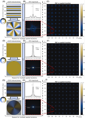
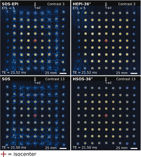
Figure 4 shows that distortions due to CCGF increase similarly to that predicted by Figure 3, with generally increasing distortion as distance from the isocenter (or from the center of the phantom) increases. However, the phantom in Figure 4 was placed 80 mm off isocenter in the y-direction (it was placed on the 32-channel spine coil), the points of minimum concomitant phase inhomogeneity between radial views lie at z = ± 40 mm, and thus the center vial of the phantom does not necessarily show the least artifacts. Despite this, rotation down the echo train as implemented in both HEPI and HSOS reliably removes most of the distortion artifacts.
Figures 5-7 show examples of the CCGF-induced artifacts in phantoms in the coronal orientation. In Figure 5, the artifact gets progressively worse with contrast index for SOS-EPI, with the wMAPE almost doubling from 0.138 to 0.236 between contrasts 1 and 3. The HEPI sequence, on the other hand, maintains image quality even at later contrasts. Notably, the majority of CCGF-induced artifacts are removed when scanning in the transverse plane for both SOS-EPI and HEPI, as corroborated by their low wMAPE scores of around 0.07.
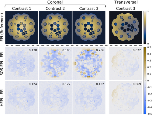
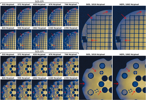
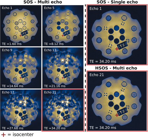
Figure 6 gives an example of the worsening of CCGF-induced artifacts at higher gradient strengths, which was accomplished by increasing the bandwidth per pixel while maintaining constant resolution. As expected, artifacts increase with greater distance from the isocenter and are more egregious in the z direction (horizontal in these images) than in the x direction (vertical). The HEPI sequence is also able to outperform the image quality of SOS scans at later contrasts in terms of CCGF effects.
Figure 7 shows that CCGF effects are indeed a concern even in standard SOS imaging. A multi-echo SOS acquisition is shown to have increasing artifacts with later echoes at positions further from isocenter (isocenter indicated by red crosshairs), whereas a single echo acquisition at the latest TE does not incur these artifacts. Additionally, HSOS imaging with 36° inter-echo rotation, as shown in the bottom right of Figure 7, was also able to virtually eliminate these CCGF-based artifacts and produce similar image quality to the single-echo scan. This indicates that CCGF produce substantial artifacts on top of the effects of given that the effects should be equivalent between the single and multi-echo acquisitions for the same TE.
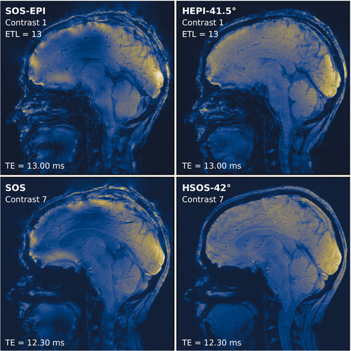
Figure 8 shows the effects of CCGF on sagittal brain images acquired using SOS-EPI, HEPI, SOS, and HSOS trajectories. Image quality is markedly improved in HEPI and HSOS relative to SOS-EPI and SOS. Notably, the CSF region just under the skull is fraught with artifacts in SOS-EPI and SOS, whereas most of these artifacts are removed in HEPI and HSOS. Additionally, contrast across the whole brain is much more uniform in images acquired using the helical trajectories.
5 DISCUSSION
5.1 Overview
In this work, we demonstrated that trajectories with variations in view angles between TRs (as opposed to within a given TR) suffer from CCGF-induced in-plane k-space phase variation between views in nonaxial scans, which can lead to notable voxel-dependent PSF distortion and dramatic effects on qualitative and quantitative image quality. This unique style of artifacts was found to appear in long readout radial-based trajectories such as multi-echo radial imaging and SOS-EPI, as opposed to long-readout Cartesian or spiral imaging that have relative uniformity of concomitant gradient phase between TRs. To overcome this challenge, we proposed the addition of a large azimuthal rotation between readouts within a given TR, when multiple readouts are employed, to produce a more constant average concomitant gradient phase with time across TRs. To accomplish this, we introduced the HEPI and HSOS trajectories, where the azimuthal view direction is incremented down the echo train. This rotation is shown to be crucial for enabling multi-contrast versions of hybrid radial-Cartesian EPI sequences, which before this work had yet to be accomplished. Azimuthal rotation down the echo train, as done in HEPI and HSOS, is shown in simulation, phantom scans, and in vivo brain scans to reduce artifacts compared to hybrid radial-Cartesian EPI (e.g., RAZER,14 TURBINE,15 and SOS-EPI16) and multi-contrast SOS acquisitions.
5.2 Implications for design of radial-based trajectories
To achieve the artifact reduction shown in this work, we found that larger rather than smaller rotations between readout lines down the echo train are needed, with the in-plane phase variation approaching a minimum as the rotation increment approaches 90°. In practice, due to (1) increasing time required for large rotations, (2) concomitant gradient phase arising from the azimuthal rotation blips themselves, and (3) the overlap of other gradient ramps with the inter-contrast rewinder in HEPI, a good trade-off angle for our implementations was found to be closer to 40–50°, as in the HEPI-2π/7 trajectory in Figure 2. However, even in contrast 1, where this overlapping gradient issue is absent, only marginal improvement is seen in simulation with rotation greater than ˜50° (see Figure 2C bar plot). Notably, even rotation by half that is sufficient to remove most of the in-plane CCGF-induced phase variation across k-space for an echo train length of 7. In fact, in each of the HEPI trajectories shown in Figure 2, the overall concomitant gradient phase across radial views converges to a small range at the end of each contrast, which results in consistent and smaller, as opposed to increasing, CCGF artifacts across all contrasts. In general, for HEPI, rotation of an integer multiple of 180° in total down the echo train will eliminate the sharp increase in CCGF effects across multiple contrasts due to this unification of the concomitant gradient phase by the end of each contrast, regardless of the echo train length. However, high image quality across contrasts still requires large rotations between each readout as indicated above.
In our preliminary work, we noticed an increase in CCGF-based artifacts in HEPI when phase correction lines were acquired in every TR as opposed to during a pre-scan. This is because the three-echo phase correction lines that are standard in our sequence are all acquired at the same view angle as the starting readout line of their respective TR and thus contribute to concomitant phase nonuniformity across TRs. Therefore, we opted to relegate the phase correction lines to the pre-scan. Future study is needed to determine the cases in which the increase in CCGF effects is outweighed by imaging improvements introduced from acquiring phase correction lines every TR. Such a study would likely also require robust B0 inhomogeneity correction, which was not investigated in this work.
The CCGF artifacts shown in this work are of particular concern in fast, multi-contrast, long-readout radial trajectories due to the high gradient amplitudes used for readout gradients and intermediate gradient blips alike. Whereas HEPI and HSOS were able to reduce the phase nonuniformity between readouts in different TRs, this nonuniformity is not completely removed in coronal and sagittal scans. Thus, increases in gradient strength will still produce CCGF-induced artifacts in HEPI and HSOS, just to a much lesser degree than in SOS-EPI. Relaxing any parameter to decrease the overall gradient strength will reduce CCGF-based artifacts and improve image quality both in SOS-EPI and HEPI trajectories. Therefore, larger voxel dimensions, decreased segmentation in the blip direction, reduction in readout bandwidth, and reduction in the echo train length will improve image quality and quantitative fidelity until CCGF-induced effects become negligible.
5.3 Relation to previous work
We note that Rettenmeier et al.19 presented a rotating hybrid radial-Cartesian EPI trajectory similar to HEPI. However, HEPI differs in the use of a multi-contrast readout and a larger azimuthal rotation between readouts down the echo train to lessen CCGF effects as described previously. Though this added rotation does increase the minimum TR due to increased echo spacing requirements, and thus gives additional sensitivity to B0 inhomogeneity and noise as described by Rettenmeier et al.,19 this work suggests that larger rotations actually may serve to improve rather than decrease image quality due to decreased CCGF-based artifacts.
In this work, we show that CCGF-induced artifacts are especially of concern in multi-contrast radial acquisitions. We note that this is the first work to describe and notice the presence of these artifacts, though there has been long time usage of SOS imaging and multiple implementations of hybrid radial Cartesian EPI.14-19 Several factors could be at work to produce stronger artifacts in this work compared to the other implementations of SOS-EPI, including the use of multi-contrast acquisitions in this work compared to single-contrast acquisitions; the use of liquid phantoms, B0 inhomogeneity, and sharp spatial changes therein; the lack of more sophisticated phase corrections or reconstruction algorithms such as conjugate phase reconstruction or its derivatives; and potentially uncorrected hardware gradient delays. However, regardless of the source, HEPI and HSOS are shown in this work to reliably reduce artifacts seen with SOS-EPI and multi-contrast SOS. Future work is needed to evaluate these trajectories quantitatively in phantoms and in vivo for diagnostic applications.
5.4 Study limitations and future work
The theory presented in this work has a few limitations. First, we specifically neglected intra-voxel dephasing due to concomitant fields. Hofstetter et al. showed that substantial signal loss can occur due to CCGF and can adversely affect quantitative measurements.20 Given this, the loss of signal shown in our simulations would be worsened in real acquisitions. Also, the addition of B0 inhomogeneity with intravoxel dephasing denotes synergistic effects between CCGF and B0 inhomogeneity. Whereas concomitant gradient phase will be unipolar, phase accrual due to B0 inhomogeneity can be positive or negative relative to that of on-resonance spins. As a result, regions with B0 inhomogeneity can either further dephase or potentially rephase signal loss or displacement produced by CCGF depending on their respective levels of off-resonance. More complex results could occur at regions where the spatial derivative of B0 inhomogeneity is largest. This is a subject for future study.
A more robust version of the PSF formalism used in this work has been developed that is more accurate in low-field MRI by incorporating deflection of the magnetic field during readout.2 However, the simpler version presented here was sufficient for understanding the phase variation artifact described at high field because the neglect of magnetic field deflection contributes negligible errors when the ratio of the applied gradients' strength to the main magnetic field strength is ≪1.2 Extension of their formalism to radial and hybrid radial-Cartesian EPI may be necessary to adequately describe those trajectories' phase behavior at low fields but is outside the scope of this work.
As with other EPI trajectories, HEPI will still be subject to chemical shift artifacts when both fat and water are present, primarily down the phase encoding direction. Existing fat saturation or fat–water separation methods can be employed in these cases if needed. The effectiveness of fat–water separation methods with this trajectory is another subject for future research.
In this work, a focus was put on mitigating CCGF-induced phase nonuniformity in acquisition as opposed to corrections during reconstruction. Whereas CCGF-induced effects can sometimes be at least partially removed post-acquisition via various methods, such as via conjugate phase reconstruction or its derivatives,11, 12 cost-function iterative minimization, or algebraic reconstruction,26, 27 this is not always the case. When artifacts are especially severe and/or if the underlying magnetic fields are sufficiently nonuniform, the resulting signal loss may be unrecoverable even with an analytic model.26 Additionally, methods such as conjugate phase reconstruction that assume a static field inhomogeneity may not be as effective for nonrotated long readout radial scans because we have shown that this inhomogeneity field, or equivalently, the rate of concomitant gradient phase accrual, can vary substantially during the acquisition depending on the view angle. Importantly, in the cases of HEPI and HSOS, where the variation in concomitant gradient phase between different radial views is not large, the concomitant gradient phase more closely approximates the phase accrual from an additional static B0 field, and thus conjugate phase reconstruction could prove useful for HEPI and HSOS when B0 inhomogeneity is strong. Additionally, for the fast dynamic scans in which these CCGF effects are especially prevalent, fast reconstruction time is often desired. This precludes the use of computationally expensive reconstruction corrections and instead calls for prevention of image artifacts during acquisition. In situations where reconstruction time is not a concern, these methods may find utility. However, it is unclear to what degree these methods would be able to correct for the strong CCGF-induced variation at later contrasts for the nonrotated multi-echo radial scans, as shown in this work. This is a subject open for further research.
6 CONCLUSION
Concomitant gradient fields are shown to play a non-negligible role in imaging with long readout radial-based trajectories. These artifacts are shown to be caused at least in part by the variation in phase between radial views. By utilizing extra azimuthal rotation between readout events as done in HEPI and HSOS, the variation in concomitant gradient phase with view number can be substantially reduced, thereby eliminating most of the associated artifacts. These trajectories have potential applications with fast 3D dynamic imaging, and this is a subject of future work.
ACKNOWLEDGMENTS
We thank Dr. Peter Kovesi and Dr. Fabio Crameri for the excellent colormaps28-30 used in this work. We also gratefully acknowledge funding support from the Mark H. Huntsman Endowed Chair, as well as the following National Institutes of Health (NIH) grants: R01EB028316, R21EB033117, R21EB033638, R37CA224141, and S10OD018482.
APPENDIX A
The rest of the derivation remains equivalent to that given in the text.
Open Research
DATA AVAILABILITY STATEMENT
The data that support the findings of this study are available from the corresponding author, M.M., upon reasonable request.


