Dipolectric antenna for high-field MRI
Abstract
Purpose
To introduce the dipolectric antenna: a novel RF coil design for high-field MRI using a combination of a dipole antenna with a loop-coupled dielectric resonator antenna.
Methods
Simulations in human voxel model Duke involving 8-, 16-, and 38-channel dipolectric antenna arrays for brain MRI were conducted. An 8-channel dipolectric antenna for occipital lobe MRI at 7 T was designed and constructed. The array was built of four dielectric resonator antennas (dielectric constant = 1070) and four segmented dipole antennas. In vivo MRI experiments were conducted in one subject, and the SNR performance was benchmarked against a commercial 32-channel head coil.
Results
A 38-channel dipolectric antenna array provided the highest whole-brain SNR (up to a 2.3-fold SNR gain in the center of the Duke's head vs. an 8-channel dipolectric antenna array). Dipolectric antenna arrays driven in dipole-only mode (with dielectric resonators used as receive-only) yielded the highest transmit performance. The constructed 8-channel dipolectric antenna array provided up to threefold higher in vivo peripheral SNR when compared with a 32-channel commercial head coil.
Conclusion
Dipolectric antenna can be considered a promising approach to enhance SNR in human brain MRI at 7 T. This strategy can be used to develop novel multi-channel arrays for different high-field MRI applications.
1 INTRODUCTION
Despite a considerable SNR gain provided by ultrahigh-field (UHF) MRI, that is, at 7 T and above, a continuous pursuit for higher sensitivity remains valid and is of high interest for neuroscientists who explore the anatomy, function, connectivity, and chemical composition of human brain in vivo at the macroscopic scale.1, 2 A standard approach to increase whole-brain SNR in high-field MRI is to use multi-channel RF coil arrays.3 Conventional RF arrays are constructed using conductive loop elements with lumped components (capacitors, inductors) required for tuning, decoupling (e.g., by overlapping3 or with additional capacitive4 and/or inductive circuits5), and power matching. Although this strategy can lead to an increase in peripheral SNR, it is not expected to improve SNR in deep brain: Decreasing a loop's diameter leads to higher resistive losses and reduced quality factor. This effect was experimentally verified at 3 T by Wiggins et al., who developed a 96-channel array for brain MRI,6 and recently confirmed by Uğurbil et al. for a 64-channel array for 7 T.7 However, there are promising alternatives that can provide considerable receive gains in periphery and in deep brain at 7 T and above. Unlike at 1.5 or 3 T, RF coils at UHF operate at the interface of near and far field of electromagnetic radiation.8 This makes different types of antennas particularly suitable for UHF-MRI, and some of them can be intrinsically complementary to each other, which brings potential performance gains.
As mentioned above, increasing SNR in the center of human brain can be considered more challenging because it is not expected to be achieved simply by increasing the number of loop coil elements in a receive array.6, 7 To address this issue, multi-channel dipole antenna arrays seem to be particularly promising. Dipole antennas were first used to enhance transmit efficiency in body MRI at 7 T,8, 9 and recent reports focused on novel designs for brain MRI at different B0 field strengths: 7 T,10 9.4 T,11 and 10.5 T.12 Those findings were further supported by theoretical work from Lattanzi et al.,13 who demonstrated that dipole antennas can capture curl-free currents, which contribute to the ultimate intrinsic SNR, and their significance is expected to grow with the sample size and the Larmor frequency. The theory prescribes that a combination of dipole antennas with standard loop coils is essential to approach the ultimate intrinsic SNR.13 This was first experimentally verified by Wiggins et al. in a cylindrical phantom14; then by Ertürk et al. for body applications15; and recently by Avdievich et al., who developed a 32-channel loop–dipole array for brain MRI at 7 T.16
A very effective approach, which was proposed to enhance receive performance of standard RF coils at UHF, was to combine them with dielectric materials with high εr (high-permittivity materials [HPM]17). HPMs can be either used as passive (also known as dielectric pads) or active elements, that is, dielectric resonator antennas (DRA). Although dielectric pads were introduced to address inhomogeneities, they were also found suitable to improve SNR in human brain MRI at 7 T.18 Development of DRAs is still an active area of research, and there is an evidence showing that they can be considered an encouraging alternative to loop coil arrays at 7 T and above.19-22 DRA can be designed as a ceramic block with a desired dielectric constant εr and low loss tangent (or electrical conductivity σ). A small coupling loop can be used to excite different dielectric modes within the dielectric block. The geometry and εr of the DRA can be freely adjusted, thereby providing extra degrees of freedom to tailor the electromagnetic field distribution for particular application.
The interplay between dipole antennas and dielectric materials was studied by other authors. In particular, the New York University group23, 24 showed that integration of HPMs could be a practical method to improve RF shimming performance of a dipole antenna array and SNR. Furthermore, Brink et al. provided preliminary evidence that using a dielectric “sleeve” can help to improve transmit/receive (TXRX) performance of a dipole antenna array.25 Different modes, which can be induced by a short dipole antenna in direct contact with rectangular dielectric blocks, were studied by Ipek et al.26 as well as by Wenz and Gruetter.27 Nevertheless, a combination of a dipole antenna with an HPM with the latter acting as an active element (in fact, a DRA) was not considered so far. It was only demonstrated in a preliminary simulation study28 that mixing loop-coupled DRAs with dipole antennas should be feasible because both elements produce orthogonal electromagnetic field patterns: By aligning a dipole antenna along the central axis of a loop-coupled DRA, a very high level of isolation between these two elements can be achieved. However, until now there was no experimental validation for the idea of mixing dipole antennas with loop-coupled DRAs.
Therefore, in this work we aim to investigate potential advantages of combining two types of elements: a dipole antenna and a loop-coupled dielectric resonator antenna for brain MRI at 7 T. It is hypothesized that by using the combined approach with a higher number of elements, which are complementary to each other, an SNR increase could be achieved. Moreover, the interaction between dipole antennas and HPM could have a beneficial effect on the transmit performance of dipole antennas. Recognizing this opportunity, we here introduce a novel concept of dipolectric antenna (dipole + dielectric), which is a combination of dipole antenna with a loop-coupled, rectangular DRA. To further explore this strategy, electromagnetic simulations involving 8-, 16-, and 38-channel arrays were performed, and an 8-channel dipolectric antenna array was constructed and used in in vivo study at 7 T.
2 METHODS
2.1 Electromagnetic field simulations
Numerical electromagnetic field and specific absorption rate (SAR) simulations were performed using the finite-difference time-domain solver of Sim4Life V7.0 (Zurich Medtech, Zurich, Switzerland). In the simulations, a spherical phantom (radius = 85 mm, εr = 77, σ = 1.09 S/m) and the human voxel model “Duke” from the Virtual Family were used.29 Copper elements were modeled as perfect electrical conductors. The excitation signal was of Gaussian type (center frequency = 297.2 MHz, bandwidth = 500 MHz). The grid was manually adjusted for all the components in the simulation. The smallest mesh cell was 2 mm (“Duke” conductors, dielectric blocks, ports), whereas for the spherical phantom it was 4 mm. In each simulation, a hollow cylinder (radius = 200 mm, length = 300 mm) mimicking the head gradient insert of our MR scanner was included. The simulation data were exported as Touchstone files and used in Advanced Design System 2019 (Keysight Technologies, CA) to design the tuning/matching circuits. Subsequently, the same RF circuits were reproduced in the MATCH module of Sim4Life. The B1 data for each channel were normalized to 0.02 W input power per channel, exported, and used for the SNR calculation and optimization,30 ensuring an appropriate power normalization (see Supplementary materials). SNR was calculated using the Roemer's approach3 combined with the scattering parameter formalism proposed by Kühne.30, 31 The SAR10g for each phase setting was normalized to 1 W total input power. efficiency was defined as /√P, where P is total input power; and SAR efficiency was defined as /√pSAR10g, where pSAR10g is peak SAR averaged over a mass of 10 g for given transmit mode.
2.2 Dipolectric antenna
Dipolectric antenna was designed as a combination of a loop-coupled DRA and a dipole antenna (Figure 1). In this proof-of-principle study, a similar rectangular DRA (HyQ Research Solutions, PA) to the one in O'Reilly et al.21 was used, but with a 7.5-times lower σ value (εr = 1070, σ = 0.2 S/m). DRA dimensions were 90 × 44 × 5 mm. For the dipole antenna (length = 250 mm, conductor width = 6 mm, conductor thickness = 36 μm), a “segmented” approach (a similar one to the “bumped” dipole antenna32) was used: The antenna's feeding point along with the tuning inductors was placed 20 mm above the top of the DRA and physically connected with the antenna's arms positioned below (Figure 1).
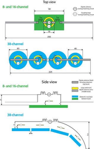
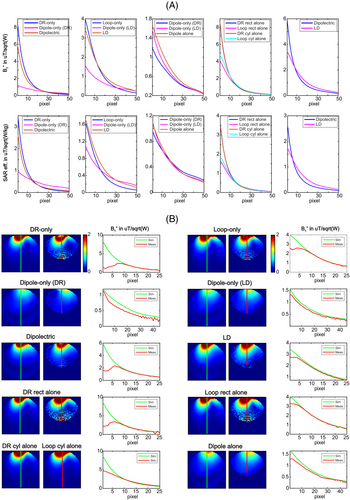
An individual dipolectric antenna was studied in simulations and MR phantom experiments (Figure 2) and was compared to a loop–dipole combined antenna; for this purpose, the DRA was replaced with a rectangular loop coil identical to that in Ref. 21: 90 × 44 mm, copper width = 5 mm. The distance between the loop coil and the dipole element for the loop–dipole antenna was the same as between the bottom surface of the DRA and the dipole element for the dipolectric antenna. The dipole element in the loop–dipole combined antenna was tuned to the Larmor frequency using two inductors L = 51 nH, and three capacitors (C = 7.5 pF) and a single capacitor with variable capacitance were used for the loop element. Several different transmit modes (see section 2.5: Transmit modes) were investigated for the dipolectric antenna. These modes correspond to the following ones for the loop–dipole antenna: loop-only, dipole-only (LD), and loop–dipole (LD). Furthermore, both combined approaches were compared to the “standalone” designs: a rectangular DRA (identical as for the dipolectric antenna), a rectangular loop coil (identical as for the loop–dipole antenna), and a segmented dipole antenna; Additionally, a cylindrical DRA and a circular loop coil of the same outer diameter as the cylindrical DRA (three capacitors with C = 10 pF; copper width = 5 mm) were studied in simulations only. The distance between each element and a spherical phantom was 5 mm.
2.3 8- and 16-channel dipolectric antenna array
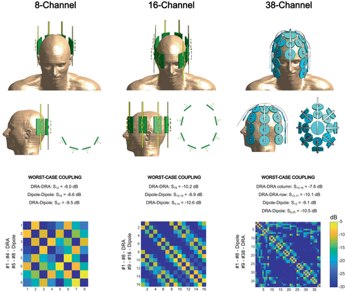
Dipolectric antenna, such as in Figure 1, was studied in two multi-channel array configurations: 8- and 16-channel. Both arrays were loaded with the head of Duke (including the shoulders). The elements of the 8-channel array were positioned at the back of the Duke's head (Figure 3) with the intent to use it for occipital lobe imaging. For the 8-channel array, the distance between the DRA was 20 mm. The elements of the 16-channel array were distributed around the Duke's head: Eight elements at the back of the head were aligned similarly to the 8-channel array, whereas the other eight were distributed such that vision through the array was feasible (Figure 3). The distance between each DRA and the surface of Duke's head for the 8-channel array was 5 mm for the two inner DRA elements and 10 mm for the two outer DRA elements (to enable fitting larger heads). The distance between each DRA and Duke's head for the 16-channel array was kept constant (5 mm). Additionally, a 16-channel dipolectric antenna array was compared with two other array designs: an 8-channel “straight” dipole antenna array (no segmentation) and an 8-channel folded dipole antenna.33 Each “straight” dipole antenna was positioned at the same distance from the surface of Duke model as distance between the surface of Duke and bottom part of DRAs. Folded dipole antenna was reproduced from the previous work33: Simulations were performed with a superior RF shield, but no passive elements for decoupling were included.
2.4 38-channel dipolectric antenna array
A different design was used for a 38-channel dipolectric antenna array (Figures 1 and 3). In this case, cylindrical DRAs replaced rectangular DRAs that were used for 8- and 16-channel arrays. Two different cylindrical geometries were used: radius1 = 30 mm, radius2 = 24 mm, thickness (both) = 5 mm. A total of 30 DRAs were positioned around the head of human voxel model Duke and distributed in eight columns (7 columns: 4 DRAs per column, and 1 column next to the forehead with 2 DRAs) and in 4 rows (top row: 8 DRAs with radius2, second row from the top with 8 DRAs with radius1, and the other two rows with 7 DRAs per row to enable vision through the array). The distance between the bottom of a DRA and the surface of the Duke's head was not constant: For two top rows, the distance was approximately 5 to 15 mm, and for two bottom rows it was approximately 20 to 30 mm. The variations in distance between particular DRAs and Duke's head arise from the fact that the array was designed to fit different head sizes. On the top of the array there was a passive dielectric block (identical to the DRA with radius1). An identical coupling loop as in Figure 1 was placed above each DRA (6 mm distance from the DRA). Eight dipole antennas were positioned so that each dipole antenna was above a single DRA column. The distance between each dipole antenna and a DRA was 10 mm. Dipole antenna length was identical as the one for 8- and 16-channel arrays, but it was bent to conform to the geometry of the array defined by the DRAs. In receive (RX) mode, all 38 of the elements (dipole antennas and DRAs) were used, whereas in TX, only dipole antennas (driven in a circularly polarized mode) were used.
2.5 Transmit modes
- Dipolectric: Both DRAs and dipole antennas actively transmit RF,
- Dipole-only: Dipole antennas actively transmit, and DRAs are terminated to 50 Ω,
- Dipole-only (DRA-open): Dipole antennas actively transmit, and the DRAs ports are defined as open circuits (this mode is supposed to mimic a scenario in which DRAs elements are detuned during TX and used as receive-only),
- DRA-only (DRAs actively transmit, and dipole antennas are terminated to 50 Ω).
16-channel array was used for this purpose because all of the elements are distributed such that a standard circularly polarized mode (45° phase increment per element) could be used. Simulations were benchmarked against: an 8-channel dipole antenna and an 8-channel DRA array. All of the simulations were also performed for the DRAs with higher electrical conductivity (σ = 1.5 S/m), which was reported previously.21
Throughout this study, when any dipolectric antenna is included in a receive performance (SNR) comparison, it is always used in “dipolectric mode”; that is, all of the elements are receiving.
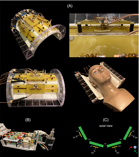
2.6 8-channel dipolectric array construction
The 8-channel dipolectric antenna array was constructed, and bench measurements were performed using a 4-channel vector network analyzer (Agilent Keysight Technologies, CA). Each dipole antenna and coupling loop was etched from a 36-μm copper layer on a 1-mm thick FR4 board. Both components (the DRA and the dipole antenna) of the dipolectric antenna were tuned to 297.2 MHz and matched to 50 ohm using standard capacitive tuning/matching networks. Three nonmagnetic variable capacitors were used per one dipolectric antenna: one for the dipole antenna, and the other two for the coupling loop. In the simulations, an inductance LD (55 nH) was used for tuning of dipole antennas. In the experimental setup, LD was realized using a hand-wound inductor with an isolated copper wire (0.5 mm-radius), number of turns (n = 3), inner diameter = 9 mm, length = 10 mm, fill factor = 3.13. The constructed 8-channel dipolectric antenna was driven in dipole-only mode. efficiency was optimized using an algorithm, which was developed earlier in our laboratory.34 For optimization, a small, hand-drawn circle-like (radius = 15 mm) mask close to the center of Duke's head was defined. The algorithm yielded a phase setting, which was later used in MR experiments: (127°, 85°, 0°, 0°).
2.7 RF interface
An RF interface was built of a two-stage 1:4 power divider (MRI.TOOLS, Berlin, Germany) and 8 TX/RX switches (MR CoilTech, Glasgow, UK). In all of the experiments, all eight DRA/dipole elements were actively receiving the signal (8 TXRX switches were used). To reduce common modes on the cables, bazooka cable traps were built. Bazooka baluns were made using a cylindrical tube of Teflon (length = 5 cm, diameter = 8 mm), including a fixed capacitor (14 pF), covered with copper tape (35 mm) over the coaxial cable (K_02252_D-08; Huber & Suhner, Naenikon, Switzerland). For the 8-channel dipolectric antenna array, two bazooka baluns per element were used.
2.8 Phantom and in vivo experiments
The 8-channel dipolectric antenna array was evaluated in phantom (spherical; radius = 85 mm; εr = 77, σ = 1.09 S/m; Siemens Healthineers, Erlangen, Germany) and in vivo experiments. All scans were performed on a Magnetom 7 T/680 mm human scanner (Siemens Healthineers, Erlangen, Germany) with a head-gradient insert (max 80 mT/m and 333 T/m/s). Informed consent was obtained from a subject according to a procedure approved by the local ethics committee. mapping was performed using SA2RAGE35: TR/TE = 2400/0.78 ms, FOV = 256 × 256 mm, number of slices = 64, slice thickness = 2.5 mm. Anatomical MR images were acquired using a 3D gradient echo (GRE) sequence: (TR/TE = 6.5/2.82 ms, slice thickness = 1 mm, FOV = 256 × 240 mm). In vivo SNR was evaluated using the Kellman approach.36 For this purpose, two separate 2D GRE scans (signal and noise-only) were acquired: TR/TE = 1000/3.37 ms, flip angle (FA) = 48°, matrix = 192 × 192, number of slices = 1 (transversal; isocenter), slice thickness = 1 mm. The noise-only data was acquired using the same parameters but with TX voltage set to 0. The resulting SNR maps were corrected for FA variations by obtaining corresponding maps (SA2RAGE: TR/TE = 2400/0.78 ms, FOV = 256 × 256 mm, number of slices = 64, slice thickness = 2.5 mm) and applying them in the following equation5: , where α is the spatially varying FA as determined by the SA2RAGE measurement and normalized for the GRE sequence; TR is the repetition time (1 s); and T1 is the longitudinal relaxation time (assumed 2.3 s for the whole brain).
3 RESULTS
Dipolectric antenna was simulated and , and SAR efficiency in a spherical phantom for different TX modes (DR-only, dipole-only [DR], and dipolectric) was compared to the those obtained for a loop–dipole combined antenna (loop-only, dipole-only (LD), LD). Furthermore, transmit performance for the “standalone” designs: A rectangular/cylindrical DRA, a rectangular/circular loop coil, and a segmented dipole antenna were evaluated (Figure 2A). The highest efficiency in the center was found for: LD (0.34 μT/√W, pSAR10g = 4.03 W/kg), standalone dipole (0.32 μT/√W, pSAR10g = 2.49 W/kg), and dipole-only (LD) and dipole-only (DR): both 0.30 μT/√W [pSAR10g = 2.05 and 1.57 W/kg]. These data resulted in the highest SAR efficiency in the center for: dipole-only (DR) (0.24 μT/√[W/kg]), dipole-only (LD) (0.21 μT/√[W/kg]), standalone dipole (0.20 μT/√[W/kg]), and LD (0.17 μT/√[W/kg]) (Figure 2A). The highest and SAR efficiency in the periphery (up to ∼2 cm depth) was found when all of the RF power was fed to the DRAs, that is for the DR-only mode as well as for the standalone rectangular and cylindrical DRAs. and SAR efficiency for the DRAs was lower in the center of the phantom when compared to their corresponding loop elements: loop-only versus DR-only (0.20 vs. 0.16 μT/√W; pSAR10g = 5.99 vs. 5.90 W/kg), rectangular loop coil versus rectangular DRA (0.20 vs. 0.18 μT/√W; pSAR10g = 5.99 vs. 5.88 W/kg), and cylindrical loop coil versus cylindrical DRA (0.18 vs. 0.15 μT/√W; pSAR10g = 6.66 vs. 6.22 W/kg). The data obtained from simulations agreed well with the phantom experiments (Figure 2B).
In simulations, 8-, 16-, and 38-channel dipolectric antenna arrays were loaded with the Duke's head, and S-matrices were obtained (Figure 3). For the 8-channel array, coupling between adjacent dipole antennas (dipole–dipole) was between −6.5 and −9.0 dB; coupling between adjacent DRAs (DRA–DRA): from −8.1 to −10.4 dB; coupling between adjacent DRAs and dipole (DRA–dipole) antennas: from −9.6 to −12.5 dB. For the 16-channel array, dipole–dipole coupling was between −7.4 and −12.5 dB; DRA–DRA: from −10.2 to −20.3 dB; DRA-dipole: from −10.7 to −19.3 dB. For the 38-channel array, dipole–dipole coupling was between −9.1 and −11.5 dB; DRA–DRA (in a single column): from −7.6 to −11.1 dB; DRA–DRA (in a single row): from −9.6 to −23.8 dB; DRA–dipole: from −10.5 to −34.5 dB.
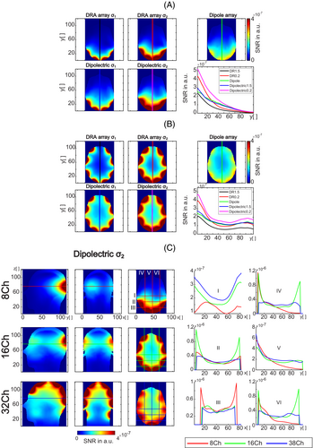
To evaluate SNR performance of a dipolectric antenna, 8- and 16-channel arrays (for two different DRA's σ: 1.5 S/m [σ1] and 0.2 S/m [σ2]) were compared with their standalone counterparts: DRA and dipole antenna arrays (Figure 4A,B). It was found that 8-channel dipolectric antenna array (σ2) provided the highest SNR in the center (the 60th pixel along profile V was considered) as well as in peripheral regions of the Duke's head. In the center, it was: 1.12-fold higher versus 4-channel dipole antenna array; 1.19-fold higher versus 8-channel dipolectric antenna array (σ1); twofold and 3.2-fold higher versus 4-channel DRA array for σ2 and σ1, respectively (Figure 4A). Similarly, SNR performance of a 16-channel dipolectric antenna array (σ2) was superior in the periphery and in the center of Duke's head. In the center, it was 1.23-fold higher versus 16-channel dipolectric antenna array (σ1); 1.27-fold higher versus 8-channel dipole antenna array; 1.43- and 2.38-fold higher versus 8-channel DRA antenna array for σ2 and σ1, respectively (Figure 4B). A peripheral SNR was compared for one point (10th pixel along profile V) in the brain behind the skull. It was found that SNR for 8-channel dipolectric array was between 1.22 and 2.3-fold higher than other designs (Figure 4A), whereas the SNR for 16-channel dipolectric array was between 1.23- and 2.54-fold higher than its counterparts (Figure 4B). Finally, 8- and 16-channel dipolectric antenna arrays (0.2 S/m) were compared with a 38-channel dipolectric antenna array (Figure 4C). For the latter, a substantial SNR gain in the center of Duke's head was found: 1.27-fold and 2.3-fold versus 16- and versus 8-channel array, respectively.
To evaluate transmit performance of a dipolectric antenna, different TX modes were investigated for a 16-channel dipolectric antenna array. For σ2 (excluding the dipole-only for which a minimal loss was observed), significant gains compared with σ1 were observed (Figure 5A). The reference 8-channel folded and 8-channel “straight” dipole antenna array provided the highest peak efficiency in the center of Duke's head: 0.67 and 0.65 μT/√W, respectively. Dipole-only σ2 (DR-open) was the mode that provided the third highest peak efficiency (0.62 μT/√W) when compared with the other ones: dipole-only (0.52 μT/√W), DRA-only (0.47 μT/√W), and dipolectric (0.29 μT/√W). Furthermore, it was found that efficiency for dipole-only σ2 (DR-open) was higher when compared with an 8-channel dipole antenna array (0.55 μT/√W), and 8-channel DRA arrays (σ1 and σ2): 0.36 and 0.55 μT/√W, respectively. The highest averaged efficiency across the central axial slice was found for the dipolectric antenna array driven in dipole-only (DR-open) mode: 0.48 ± 0.17 μT/√W. However, the highest homogeneity was observed for the reference dipole arrays: 8-channel straight (0.44 ± 0.11 μT/√W), folded (0.42 ± 0.09 μT/√W), and segmented dipole antenna array (0.38 ± 0.09 μT/√W). Finally, efficiency for all three dipolectric antenna arrays—8-, 16-, and 38-channel—were compared, and significant increase for 16- and 38-channel dipolectric antennas arrays versus 8-channel counterpart was observed (Figure 5B). To further investigate transmit performance of the 16-channel dipolectric antenna, SAR efficiency was estimated for different TX modes and summarized in Table 1 (see Figure S1 for the SAR efficiency distribution).
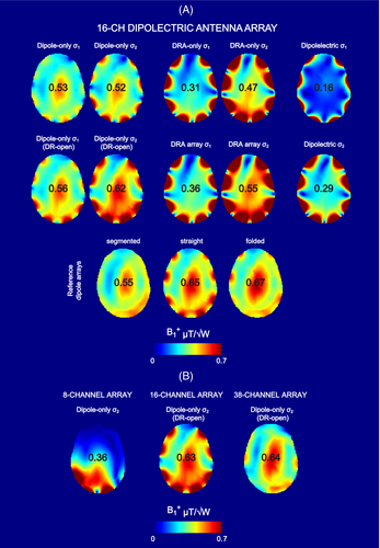
| TX mode | max center μT/√W | avg slice μT/√W | SAR efficiency μT/√(W/kg) | pSAR10g (W/kg) |
|---|---|---|---|---|
| Dipole array (folded) | 0.67 | 0.42 ± 0.09 | 0.96 | 0.49 |
| Dipole array (straight) | 0.65 | 0.44 ± 0.11 | 0.99 | 0.43 |
| Dipole-only σ2 (DR-open) | 0.62 | 0.48 ± 0.17 | 0.97 | 0.42 |
| Dipole-only σ1 (DR-open) | 0.56 | 0.39 ± 0.10 | 1.00 | 0.32 |
| Dipole array (segmented) | 0.55 | 0.38 ± 0.09 | 0.91 | 0.38 |
| DRA array σ2 | 0.55 | 0.70 ± 0.50 | 0.55 | 0.49 |
| Dipole-only σ1 | 0.53 | 0.34 ± 0.08 | 1.00 | 0.29 |
| Dipole-only σ2 | 0.52 | 0.37 ± 0.12 | 0.99 | 0.28 |
| DRA-only σ2 | 0.47 | 0.62 ± 0.47 | 0.73 | 0.43 |
| DRA array σ1 | 0.36 | 0.45 ± 0.33 | 0.80 | 0.20 |
| DRA-only σ1 | 0.31 | 0.40 ± 0.31 | 0.71 | 0.20 |
| Dipolectric σ2 | 0.29 | 0.48 ± 0.39 | 0.50 | 0.33 |
| Dipolectric σ1 | 0.16 | 0.23 ± 0.22 | 0.40 | 0.17 |
- Abbreviations: avg, average; DR, dielectric resonator; DRA, dielectric resonator antennas; max, maximum; pSAR, peak specific absorption rate; SAR, specific absorption rate; TX, transmit.
To investigate performance of the constructed 8-channel dipolectric antenna, bench measurements were performed (Figure 6). It was found that for the 8-channel dipolectric antenna array, coupling between particular channels when the array was loaded with a spherical phantom was between −9.8 and −12.0 dB for the adjacent DR elements, between −6.8 and −10.3 dB for the neighboring dipole elements, and within the range of −11.1 and −16.6 dB between the adjacent DR elements and dipole antennas. Additionally, scattering parameter matrix measurements were performed at the bench in three different subjects (Figure S2). The worst-case reflection coefficient was found to be −10.5 dB.
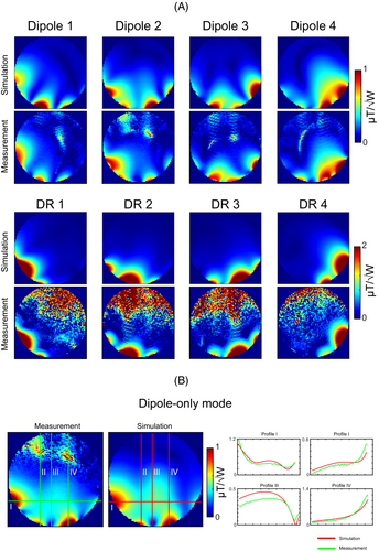
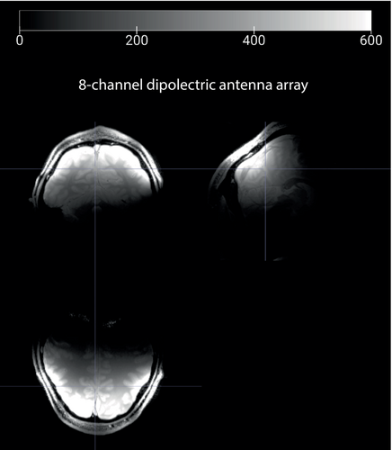
To validate electromagnetic field simulations, mapping in the spherical phantom was performed for each channel of the 8-channel dipolectric antenna array (Figure 7). The same procedure was conducted for the dipole-only phase setting (used in the final in vivo experiments). A good agreement between the simulations and measurements was observed. The simulation data did not include 1.25 dB power loss per channel, which could explain minor quantitative differences. Dipole-only phase setting (127°, 85°, 0°, 0°) with the maximum SAR10g of 0.53 W/kg (normalized to 1 W total forward power) was used in the study. An explicit 50% margin of safety was considered to determine the conversion factor (k-factor) for in vivo experiments. There was also an implicit safety margin (25% power loss per channel on the way between the coil plug and the coil). The same TX mode was used to obtain exemplary anatomical images (Figure 8).
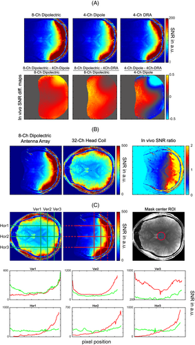
To determine SNR performance of the constructed 8-channel dipolectric array, in vivo experiments were conducted. To evaluate how significantly different types of elements (dipole antennas and DRAs) contribute to the overall SNR in different brain regions, the 2D GRE data were reconstructed, and SNR ratio maps were provided. It was found that in deeper located regions, dipolectric array contributed to an SNR increase of 1.1- to 1.2-fold versus four dipole antennas, and 1.5- to 2-fold versus four DRAs. In the periphery, it was 1.3- to 2.2-fold higher versus four dipole antennas and up to 1.2-fold higher than four DRAs (Figure 9A). The data obtained for the dipolectric array was benchmarked against a commercial head coil with 32 RX channels, and apparent (up to threefold) peripheral SNR gains were observed (Figure 9B) with an SNR ratio map highlighting the sensitivity region of the 8-channel array for which the SNR is greater or equal than the one for 32-channel coil. The SNR for the 8-channel array decreases when approaching the center of the subject's brain: approximately 0% to 40% drop (along the central horizontal profile, Hor2; see Figure 9C) versus the commercial coil. The central SNR, which was evaluated for a circular region of interest in the center of the subject's head (Figure 9C), was higher by 31.9% ± 13.2% for the commercial coil.
4 DISCUSSION
In this work, a novel RF coil design for ultrahigh-field MRI—dipolectric antenna—was introduced. Dipolectric antenna is based on the principle of mixing a dipole with a loop-coupled DRA: By aligning these two elements together such that electromagnetic fields produced by them are orthogonal to each other, a very low interchannel coupling can be achieved. Using this strategy, high-channel count RF arrays can be developed; here, we investigated dipolectric antennas that were built of 8-, 16-, and 38-channels. Finally, an 8-channel array was designed, constructed, evaluated, and benchmarked against a 1 TX/32 RX Nova coil in in vivo MRI experiments at 7 T.
In simulations, 8-channel and 16-channel dipolectric antenna arrays were loaded with human head (Duke), and the SNR for several types of arrays (dipole array, DRA array [σ1, σ2], and dipolectric antenna arrays [σ1, σ2]) was evaluated (Figure 4). It was demonstrated that 8-channel dipolectric antenna array can provide considerable SNR gains verus other designs: between 1.12- and 3.2-fold in the center and between 1.22- and 2.3-fold in the periphery. Similar gains were observed when 16-channel dipolectric antenna array was compared with other designs: between 1.23- and 2.38-fold in the center and between 1.16- and 2.1-fold in the periphery. The data showed that substantial SNR gains (center and periphery) are achievable when dipolectric antenna arrays with lower σ values are used.
It was also found that higher number of elements in a dipolectric antenna array can lead to a substantial SNR increase in the center of the Duke's brain. For this purpose, three designs (all σ2)—8-, 16-, and 38-channel—were compared (Figure 4C). The data indicate that the highest SNR in the center of the brain can be obtained with the 38-channel array: 1.27-fold higher than the one for the 16-channel array, and even up to 2.3-fold higher than for the 8-channel array.
In TX, it was shown that dipole-only σ2 (DR-open) mode should be considered as the one that is the most suitable for whole-brain MRI. This was possible because for the dipole-only mode, dipole antennas coupled with DRAs (the coupling loops were terminated to 50 ohm in TX), whereas in dipole-only mode (DR-open) that coupling was significantly reduced (an open circuit in each coupling loop during TX), which turned out to be advantageous in TX (Figure S3). This mode provided the highest efficiency (0.62 μT/√W) and one of the highest SAR efficiencies (0.97 μT/√[W/kg]) in the center of the Duke's head for 16-channel dipolectric antenna array; efficiency was 1.12-fold higher and SAR efficiency was 1.06-fold higher (pSAR10g was 16% lower) than the ones for a standalone, 8-channel dipole antenna array (Table 1). However, homogeneity in the analyzed slice was lower in the case of dipolectric antenna array (0.48 ± 0.17 μT/√W vs. 0.38 ± 0.09 μT/√W). In receive mode, when all elements were active (dipolectric mode), 1.28-fold (center) and 1.7-fold gains were observed versus the dipole antenna array. The data indicate that dipolectric antenna arrays for whole-brain MRI should be driven such that dipole antennas act as TXRX elements and DRAs as receive-only. This approach is expected to maximize TX and RX performance of a dipolectric antenna array.
An experimental SNR was evaluated for the constructed 8-channel dipolectric antenna array and compared with a commercial 32-channel receive-only array, demonstrating significant peripheral SNR gain (even up to threefold) and a lower central SNR by 31.9% ± 13.2%, which was estimated for a small ROI in the center of the brain (Figure 9B,C). In vivo SNR ratio maps revealed a large region in the subject's brain where SNR for the dipolectric array is equal or greater than the one for the Nova coil (even in the vicinity of the center of the brain). We also investigated the SNR contribution from different types of elements in the 8-channel dipolectric antenna array (Figure 9A). We found that the experimental data stays in a very good agreement with our simulation data provided for the same array (Figure 4A), indicating that our SNR calculations are valid and can be used to draw conclusions related to the receive performance of dipolectric antenna arrays with a higher number of channels. Note that the number of receive channels is fourfold lower for the constructed dipolectric antenna array; and for a fair comparison, a 38-channel dipolectric antenna array would be a more suitable candidate. The fact that such an array was not developed yet can be considered a limitation of our study. However, simulations showed that the central SNR for 38-channel array can be even up to 2.3-fold higher than the one for the 8-channel dipolectric array. A simple extrapolation of our results (assuming that central SNR for the 38-channel array is 2.3-fold higher vs. the 8-channel array) would result in a 1.6-fold SNR gain versus the Nova coil. Recently, Avdievich16 reported a 20% SNR gain in the center of human brain using their 32-channel loop–dipole array versus the Nova coil. This would mean that the 38-channel dipolectric antenna array could provide a 1.4-fold gain versus the Avdievich design. Unfortunately, due to variations in loading (Duke vs. the subject) and losses that were not included in the simulations (cables, etc.), our results cannot be directly extrapolated. If a similar loss factor (25%), as for transmit field mapping for the 8-channel array (Figure 7), is considered for the 38-channel dipolectric antenna array, the SNR gains would be reduced to 1.35- and 1.15-fold versus the Nova head coil and the Avdievich's approach, respectively. To summarize, the observed SNR gains can be considered significant, and sufficiently promising to consider the development of a 38-channel array.
Although homogeneity estimated for the 16-channel dipolectric antenna array driven in dipole-only (DR-open) mode was lower, it was found to be a more efficient transmitter than the reference 8-channel segmented dipole antenna array (26% higher slice averaged efficiency and 10% higher SAR efficiency). However, in this work we also simulated an 8-channel folded dipole antenna array,33 which was proposed earlier for brain MRI at 7 T, showing superior TX performance versus 8 TX/32 RX Nova coil. This comparison is even more relevant because a very similar design was used in a 32-channel loop–dipole combined array for brain MRI at 7 T published very recently.16 Peak efficiency (0.67 μT/√W) in the center of Duke's head was found to be 8% higher for the 8-channel dipole antenna as well as homogeneity (0.42 ± 0.09 μT/√W), but an averaged efficiency across the central axial slice was higher for the 16-channel dipolectric antenna array driven in dipole-only (DR-open) mode: 0.48 ± 0.17 μT/√W. Due to higher pSAR10g for the 8-channel folded dipole antenna, SAR efficiency in the center of Duke's head was slightly lower when compared with the 16-channel dipolectric antenna array (0.96 vs. 0.97 μT/√[W/kg]). Also, note that TX performance provided by the folded and “straight” dipole elements was comparable (Figure 5) (Table 1). Nevertheless, the data indicate that dipolectric antenna arrays can be also considered as efficient RF transmitters for brain MRI at 7 T. We also estimated an optimal SNR for the 8-channel folded dipole antenna array (Figure S4) and found that it was outperformed by the 16-channel and 38-channel dipolectric antenna arrays; the data indicate that the 38-channel dipolectric antenna array can provide more than 50% higher central SNR, along with a massive peripheral SNR increase versus the 8-channel folded dipole antenna array. Interestingly, in the case of loop–dipole combination, receive-only loops can have a detrimental effect on TX performance of a dipole antenna array.10, 16 In the case of a dipolectric antenna, on the contrary, the DRAs have a beneficial effect on TX performance (what can be tentatively called a “dielectric pad effect”), and this can be considered an advantageous feature of dipolectric antenna.
In all of our simulations, the DRAs with a lower electrical conductivity (σ2 = 0.2 S/m) provided significantly higher transmit and receive performance when compared with the DRAs with a higher σ1 = 1.5 S/m. The higher value was reproduced from previous work,21 which reported on a very low coupling between array's elements when σ1 was used. Our data indicate that losses within the DRA, which can be associated with a 7.5-fold higher σ (σ1), are more dominant than losses due to increased interelement coupling for lower σ (σ2). This led to substantially diminished performance of DRA arrays and dipolectric antenna arrays (σ1 vs. σ2) (Figures 4 and 5).
Dipolectric antenna is a novel approach that can be tailored for a wide range of applications: The geometry of DRA as well as its electrical properties can be also optimized for imaging of different anatomical structures. Furthermore, ceramic materials can be currently developed in an impressively wide range of dielectric constants and electrical conductivities, and this should provide a motivation to explore such structures in the context of novel RF concepts tailored for different B0 field strengths. Also, note that the dielectric block does not necessarily have to be designed as a homogeneous structure37; mixing dielectric materials of different electrical properties could be considered as promising aspect of the future DRA optimizations. The same applies to the geometry of the dipole antenna and the distribution of the lumped components on the antenna. Preliminary simulations indicate that an optimal DRA εr value might be different than the one that was used in this study (Figure S5). The data obtained for a single, loop-fed rectangular DRA, which was loaded with a spherical phantom, indicate that to achieve higher efficiency in the center, higher εr values can be considered. The εr value (1070), which was used for the purpose of this study, seems to be a good compromise between high peripheral and central efficiency. Note, however, that these data do not take into account RF interactions between (non-) neighboring dipole antennas and DRAs, which would be crucial to fully evaluate TX and RX performance of multi-channel dipolectric antenna arrays. This can be addressed by performing more time-consuming simulations involving high-channel count arrays (e.g., 38-channel) with the DRA's εr set as a variable. To summarize, further, application-oriented optimizations of the DRA and dipole antenna are not only possible but are expected to bring additional performance gains.
To conclude, we introduced the concept of dipolectric antenna, and we showed that it can be a promising approach for ultrahigh-field MRI applications.
ACKNOWLEDGMENTS
The authors would like to thank Jeremie Clement (currently at Siemens Healthineers) for valuable discussions on multi-channel SNR reconstruction. The authors acknowledge access to the facilities and expertise of the Center for Biomedical Imaging (CIBM), a Swiss research center of excellence founded and supported by Lausanne University Hospital (CHUV), University of Lausanne (UNIL), Ecole polytechnique fédérale de Lausanne (EPFL), University of Geneva (UNIGE), and Geneva University Hospitals (HUG). Open access funding provided by Ecole Polytechnique Federale de Lausanne.


