Effect of the ironing process on ABS parts produced by FDM
Abstract
In this work, the effect of a thermal process termed ironing on the superficial, mechanical, and dimensional properties of Acrylonitrile Butadiene Styrene (ABS) parts produced by fused deposition modelling (FDM) is evaluated. Three sets of samples for each studied parameter were manufactured. Cubic samples were used to evaluate the influence of the process in the average surface roughness (Ra) of top layers. Prismatic beams and plates were chosen to evaluate the interlaminar strength (ILS) and warping of parts, respectively. A Python script was developed to enhance the applicability of process. Although ironing may influence the thermal behaviour of deposited layers, it was not effective in enhancing the ILS of parts, due to the generation of geometric irregularities. The results show that ironing can reduce the Ra of ABS parts up to 60% and distortion levels by 33%. The study suggests ironing as an alternative postprocessing technique for FDM parts.
1 INTRODUCTION
In the last decade, the use of additive manufacturing (AM) technologies for the fabrication of personal and industrial products increased significantly.1 AM technologies present significant advantages when compared with traditional fabrication methods, namely, high degree of freedom, reduction of assemblies, flexibility to produce tailored products, short production times, and the possibility to produce small batches with reduced costs. The attractiveness of AM technologies resulting from its inherent technical features and disruptive character lead to expect that the application of additive processes will continue to increase in future years.2 A commonly used AM technology today is fused deposition modelling (FDM) due to the widespread use of personal 3D printers that allow the manufacturing of parts simply and inexpensively. The FDM process is based on the extrusion of heated feedstock plastic filaments through a nozzle tip to deposit layers onto a platform to build parts layer by layer directly from a digital model of the part.3 Some of the benefits of FDM are related with the simplicity of the process, low material waste, low cost, and the potentiated design freedom allowed during modelling, conception, and product development stages. Its major limitations are linked to surface roughness and geometrical accuracy of parts, low build speed, scalability of costs, reduced choice of materials (mainly thermoplastics), warping effect, and low interlaminar strength (ILS).3, 4 Although some of the limitations of FDM are intrinsically related on the process, others, such as low surface finish, accuracy, warping effect, and low ILS, are dependent of FDM process parameters. These limitations can be mitigated either by the optimization of the FDM parameters5-9 or by postprocessing techniques10-12 One postprocessing technique dedicated to improving the surface finish of FDM parts is the ironing process, available on the 3D printer Ultimaker 3. The ironing process consists in passing the top surface of a part with the heated nozzle of the FDM extruder adding (or not) a low quantity of material. The ironing parameters that can be managed on this software are the nozzle temperature, ironing pattern, line spacing, ironing speed, inset (offset between the outer edge of the model and the ironing path), and material flow. Another limitation derived from the specificity of the FDM process is that the bonding between successive layers is weaker along the printing direction (Z), leading to low ILS of parts. The strength of the bonding between successive layers depends on the management of the thermal flow during the deposition. Several approaches based on the control of temperature process parameters,7 laser heating,11, 13 or atmospheric plasma treatments14 can be found on literature, aiming to improve the ILS of FDM parts.
Warping (δ) is a distortion where the surfaces of the printed part do not follow the intended shape of the design.6, 15-19 Warping is caused by residual stresses on the printed material that are generated during the cooling process. If the cooling process is not uniform, there are some regions of the part that will be subjected to stress and possibly deform. Factors that affect the homogeneity of the cooling process during 3D printing include the existence of different filling regions, thickness variations, and geometric asymmetry or curvatures of the part. Warping depends strongly on the length of the stacking section (L), printing speed and infill density, increasing with L,15-17 printing speed,6, 18 and higher infill densities (more than 80%).20 Warping depends on the material and its thermal expansion coefficient, being less severe in Polylactic acid (PLA) (less than 3%) than in ABS (up to 34.53%).21 Warping increases with reduced envelope temperature on the printing chamber.17 Since warping is caused by thermal stresses, a good adhesion between parts and printing table helps to decrease warping.22, 23
In this work, authors explore the application of a modified ironing process to mitigate the limitations of the FDM process regarding the surface finish, ILS, and warping of parts. Although the proposed ironing process implies an increment of printing time, material, and energy used, its simplicity and the fact of being applied during the build process are potential advantages of the method when compared with other postprocessing methods. The influence of the ironing process on the surface finish, ILS, and warping of ABS parts is evaluated.
2 EXPERIMENTAL DETAILS
2.1 Manufacturing of specimens by FDM
Cubic and prismatic specimens (beams and plates) were manufactured on the 3D printer Ultimaker 3 with their brand of ABS filament. The 3D models were created in SolidWorks and exported in a stereolithograpy (STL) file to the slicer software Cura 4.2.1, to generate the g–code meant to be interpreted by the machine. Due to the limitations of the slicer, a Python script was developed to apply the ironing process in any desired layer of the modelled samples and generate a rotation of the same ironing path. The python script reads a conventional g–code file and searches ironing instructions present in a top layer which are then used to apply the process on different layers and manipulate its path and material flow, if needed.
Specimens were produced using an extrusion temperature of 250°C, a nozzle diameter of 0.4 mm and an infill density of 100%. The temperature of the platform was 90°C for cubes and beams. For plates, to induce a controlled level of warping, the temperature of the platform was set to 74°C. The printing speed was 30 mm/s for the first layer, external layers (top and bottom), and contours. A printing speed of 60 mm/s was chosen for internal contours and filling layers. Number of contours is 2 with a thickness of the contours, tops and bottoms equal to 0.8 mm, while the height of the initial layer was set to 0.27 mm.
Cubic samples (Figure 1A) were produced with a layer thickness of 0.2 mm, raster angles of (−45°/45°) and (0°/90°). The ironing process on cubic samples was applied on the top layer of cubes with a zigzag pattern, line spacing equal to 0.1 mm and material flow of 10%. The ironing pattern was applied in parallel to the printing pattern of the top layer. The ironing speed was 20 mm/s. The values for inset were 0.150 or 0.175 mm. ABS beams (Figure 1B) were produced with a layer height of 0.15 mm, a raster orientation of (−45°/45°) and a deposition speed of 60 mm/s. The ironing process on beams was applied in between n alternated layers (n = 4, 8, and 16) without adding material (0% flow), with an inset of 0.150 mm and an ironing speed of 25 mm/s. ABS plates (Figure 1C) were produced with a layer height equal to 0.15 mm, a raster orientation of (−45°/45°), and deposition speed of 60 mm/s. The ironing process on plates was applied after one of the three first layers of the specimens without adding flow material (0% flow), with an inset of 0.150 mm and an ironing speed of 25 mm/s. The geometry of the specimens and the applied ironing scheme are shown in Figure 1.
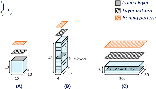
In the cubic samples, material usage in specimens with ironing increased slightly due to the 10% extrusion flow. Manufacturing time increased by more than the time it would take to print an extra layer since ironing speed is less than printing speed. As for energy consumptions, the increment of final energy consumption of the cubic specimens where ironing was performed is equal to the energy consumption of a normal sample plus the energy of one extra deposition layer. The measurements were obtained with a commercial energy consumption meter (EnergyOT), with a 15-second temporal resolution.
2.2 Optical profilometry measurements
Optical profilometry measurements were done on the top surface of ABS cubic samples. To increase the ABS surface reflectivity, the top surface of the samples was coated with reflective coating. The reflective coating (Au–Pt) was deposited on a sputtering system (Quorum–Q150TES) using a current of 40 mA and evaporation time of 60 seconds. The profilometry measurements based on the white light interferometry method were performed on the profilometer Profilm 3D with a 20× objective. The surface scanned area was 1.0 × 0.85 mm2. The raw data were acquired using the envelope peak analysis. The raw data files were exported and postprocessed with the software “Profilm Online.” The average roughness (Ra) of the cubes top surface was determined considering the entire scanned area and along a perpendicular line relative to the deposition path of the final top layer. For each experimental condition, two measurements representative of the cubes surface were considered.
2.3 Flexural tests
Three-point bending tests following the standard ASTM D790 were performed on a universal testing machine (INSTRON 5566) with a load cell of 50 kN, crosshead speed of 0.5 mm/s, a support span of 30 mm, and a rod radius of 6.0 mm, until the failure of ABS beams occurs. The load-displacement curves were recorded. For each experimental condition, five measurements were considered. The ultimate flexure stress (UFS) and the flexural modulus (EF) were calculated.
2.4 Sectional profiles geometry measurements with a scanner
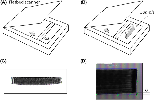
The measurements of the profile geometry of the ABS plates were performed with a flat bead scanner from a commercial printer (HP OfficeJet 4630) (Figure 2A). The contact image sensor (CIS) from the scanner is a 216 × 297 mm area sensor with an optical resolution of 600 dpi (0.04 mm). ABS plates were placed on the top of the scanner (Figure 2B), and for each profile, an image was collected and then processed in a sequence of steps. First, the image is converted to binary colour scheme (Figure 2C) and then imported to SolidWorks. After, in the program console, several points (30) were collected along the perimeters of each specimen, defining its geometry by a polynomial extrapolation. The warping (δ) was calculated by the average maximum difference, in z direction, between the extracted value and the theoretical dimension (Figure 2D). The experimental error of the measurement was computed with the pixel width of the acquired images. For each experimental condition, 10 measurements were considered.
3 RESULTS
3.1 Optical profilometry
Figure 3 displays the magnified views of the coated top surface specimens together with the applied ironing schemes and top surface profiles of the ABS cubes estimated by optical profilometry.
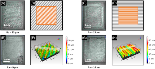
From the data present in Figure 3, it is possible to observe that the Ra of the surface of samples decreased when the ironing process was applied. The global results show a maximum reduction from 23 to 9 μm (variation of 60%) of the surface Ra of ABS cubes when the ironing process was applied. It was also noted that the results show low dependency of the Ra value with the estimation method (area or perpendicular profile line), with a maximum variation of 10% between them. The obtained value of 9 μm for the Ra is comparable with the best reported values of 10 μm obtained by optimization of the FDM parameters for ABS,24 being inferior to the values of Ra reported for PLA (more than 20 μm)25 and superior to the optimal solutions (4 ± 1.5 μm) founded on Akande.26 Postprocessing methods involving 3D chemical melting can achieve Ra values of 10 μm,27 while the Ra values for posttreatments with acetone are inferior to 2.5 μm.28 The post treatments with CO2 lasers lead to Ra values in the submicron range.29 Considering that the results were obtained adding a 10% material flow during the ironing process (default value in the slicer software), in future studies, the influence of material increment should be addressed, and the effect of a purely thermal procedure in the surface roughness of FDM parts quantified.
3.2 Flexural tests
Figure 4A displays the UFS and EF of the ABS beams, highlighting that samples where the ironing process was applied in alternated layers have lower UFS and EF, when compared with the samples without ironing. This result reveals that the thermal effect of the ironing process was not effective in increasing the ILS of ABS samples. The failure mode of specimens shows that the fracture occurs on stress concentration areas induced by the ironing process on the lateral surfaces of specimens, possibly due to retraction of the ironed layers and selected process parameters (Figure 4B).
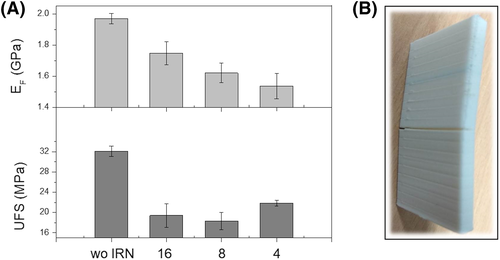
Although the ironed samples were subjected to an additional heating treatment that potentially could increase ILS,19 the potential benefits of this thermal treatment vanish with the presence of more severe geometric irregularities (stress concentration factors) on the samples surface. For comparison, the elimination of stress concentration factors (by a melting process) can increase almost two times the deflection at break and the maximum tensile strength of ABS parts produced by FDM.27
3.3 Warping
Figure 5A displays the photographs of the ABS plates without ironing and with ironing process applied on the top of the first and third layers. It is possible to observe that ABS plates that were not subjected to the ironing process present a higher level of distortion than the ABS plates subjected to the ironing process (Figure 5B). This severe level of distortion occurs in the middle of the ABS plates profile. When the ironing process is applied, there is a relocation of the maximum warping from the profile's middle (specimens without ironing) to the profile's tip (specimens with ironing).
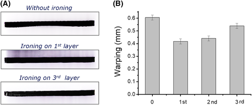
On average, in samples that were subjected to the ironing process, the warping was reduced from 0.61 (specimens without ironing) to 0.41 mm (specimens with ironing on the first layer), which represents a 33% reduction of the distortion levels. The effectiveness of ironing on reducing the levels of distortion decreases when ironing is applied on the second or third layers. The positive effect of ironing on the reduction of warping of ABS plates can be related with an increase of adhesion between layers and the printer platform (through the reduction of internal stresses), induced by the thermal energy delivered during the ironing process.18, 19, 22, 23
4 CONCLUSIONS
Based on this work, authors can conclude that the ironing process can reduce the Ra of ABS parts. On average, cubic samples displayed a decrease of Ra from 23 to 9 μm when ironing is applied, which represents an average variation of 60%. The best reported value for Ra is in line with the improvements obtained by other postprocessing methods reported in literature.
The ironing process was not effective in enhancing the ILS of prismatic parts, possibly due to the presence of more severe geometric irregularities. Even so, in further studies, manipulating ironing process parameters, such as inset and material flow, could produce samples with residual stress concentration areas that would be compensated by thermal stress releases.
The induced level of warping on plates was successfully reduced with the application of ironing in one of the first three layers, confirming the significance of thermal stress release reported in literature. The warping is increasingly reduced as the ironing layer approaches the heated bed. The maximum average distortion reduction achieved by the study was 33%.
The fact that ironing is integrated into the manufacturing process could, in the future, allow its application in the improvement of surface morphology and mechanical properties of parts produced by FDM. Due to its simplicity and low increment of material, time, and energy usage, the authors suggest further studies on the ironing process and its integration in future software developments.
FUNDING INFORMATION
This work was supported by Fundação para a Ciência e Tecnologia (FCT), through IDMEC, under LAETA project, UIDB/50022/2020. The authors also gratefully acknowledge the funding of the BigFDM project, reference PTDC/EME-EME/32103/2017. Manuel Sardinha acknowledges the MOBILE-PRO-U/ADIST project, reference 1802P.00306, for his research grant.
CONFLICT OF INTEREST
The authors declare that they have no conflict of interest.


