Process parameter dependencies of continuous and pulsed laser modes on surface polishing of additive manufactured aluminium AlSi10Mg parts
Prozessparameter-Abhängigkeiten im kontinuierlichen und gepulsten Laserbetriebsmodus beim Oberflächenpolieren von additiv gefertigten Aluminiumbauteilen (AlSi10Mg)
Abstract
enLaser powder bed fusion is a well-established 3D printing technique for metal alloys, but exhibits a poor surface quality. Laser polishing provides the possibility of a fast contact-free and fully-automatable surface treatment. This paper deals with the experimental investigation of laser polishing of laser powder bed fusion parts made of aluminium AlSi10Mg. Laser polishing is done with a 4 kW solid state disc laser in combination with a multi-axis system and a one dimensional scanner optic. The laser is operated at continuous and pulsed operation mode. The parameter study reveals a high dependency of the achievable roughness on the laser beam intensity, the track and pulse overlap, the energy density and the number of polishing passes and polishing directions. Pulsed laser polishing mode with up to four passes from different directions revealed the lowest surface roughness of 0.14 μm Ra. With respect to the initial average surface roughness of Ra = 8.03 μm a reduction of the surface roughness of greater than 98 % could be achieved. Polishing with continuous laser radiation at one polishing pass resulted in Ra = 0.23 μm at an area rate of 20 cm2/min. Laser polishing using four passes achieved a further improvement up to Ra = 0.14 μm.
Translation abstract
deDas Laser-Pulverbettschmelzen (L-PBF) ist ein gut etabliertes 3D-Druckverfahren für Metalllegierungen, weist jedoch eine schlechte Oberflächenqualität auf. Das Laserpolieren bietet die Möglichkeit einer schnellen berührungslosen und voll automatisierbaren Oberflächenbearbeitung mit kurzen Bearbeitungszeiten. Diese Arbeit befasst sich mit der experimentellen Untersuchung des Laserpolierens von Laser-Pulverbettschmelz-Bauteilen aus Aluminium AlSi10Mg. Das Laserpolieren wurde mit einem 4 kW Festkörper-Scheibenlaser in Kombination mit einem Mehrachssystem und einer eindimensionalen Scanneroptik durchgeführt. Der Laser wurde im kontinuierlichen und gepulsten Betriebsmodus betrieben. Die Parameterstudie zeigt eine hohe Abhängigkeit der erreichbaren Rauheit von der Laserstrahlintensität, der Spur- und Pulsüberdeckung, dem Energieeintrag und der Anzahl der Polierdurchgänge und Polierrichtungen. Das Polieren im gepulsten Laser Betriebsmodus mit bis zu 4 Durchgängen aus verschiedenen Richtungen erzielt die geringste Oberflächenrauheit von Ra = 0,14 μm. Bezogen auf die mittlere Ausgangsoberflächenrauheit von Ra = 8,03 μm konnte eine Reduktion der Oberflächenrauheit von mehr als 98 % erreicht werden. Das Polieren mit kontinuierlicher Laserstrahlung ergab bei einem Polierdurchgang Ra = 0,23 μm bei einer Flächenrate von 20 cm2/min. Viermaliges Laserpolieren erzielte eine weitere Verbesserung bis zu Ra = 0,14 μm.
1 Introduction
Due to ongoing investigation and development, the additively powder bed fusion (PBF) manufacturing techniques for metal alloys like laser powder bed fusion (L-PBF), have made the leap from a common prototyping technology into industrial manufacturing. The main advantages of this technology are a broad range of useable metals with the possibility to fabricate individual complex parts with good mechanical properties 1, 2. Based on the ability to fabricate parts directly from CAD models, geometrical freedom increases and enables complex part geometries and shapes 3.
However, the layer-wise process and complex geometries also cause high surface roughness and loose powder contaminated surfaces which are detrimental to most applications, especially for cleanrooms, food industry or medical implementation 4. The emerging roughness depends on the shape of the individual part orientation and the position during the manufacturing process 3, 5, 6. Possibilities to reduce the roughness in the selective laser melting (SLM) process itself were investigated, i. e. hatch strategies, laser parameters and laser remelting of each layer 7-9. However, the optimization possibilities, investigated in the selective laser melting process in order to improve the achievable surface qualities, are generally insufficient for most industrial requirements.
Today nearly all parts are reworked with the common subtractive techniques, like turning or milling with CNC-machines or manual grinding and polishing. Hence, additional options were studied, i. e. chemical polishing, abrasive blasting, mechanical polishing or laser ablation 10-13. They all have several disadvantages in common: loss of accuracy due to geometrical restrictions governed by the post processing technique, non-contact free and non-selective processing, wastage of expensive material and environmental issues.
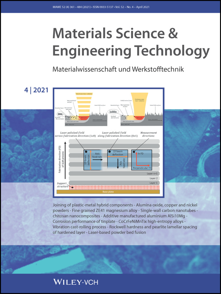
A productive way to reduce the surface roughness and structure the metallic surfaces is laser polishing 14. Laser polishing is a contact-free post processing technique with a comparable degree of geometrical freedom like the selective laser melting process itself 15. During polishing by remelting, a thin layer of the surface of the parts is made molten by the laser beam, Figure 1.

Schematic illustration of laser polishing by remelting with a) pulsed laser radiation and (b) with continuous laser radiation.
Schematische Darstellung des Laserpolierens durch Umschmelzen mit a) gepulster Laserstrahlung und b) mit kontinuierlicher Laserstrahlung.
In principal, the surface tension and capillary forces of the liquid material smooths the surface structure by a material flow from peaks to valleys 16. The irradiation, introduced by laser polishing, results in a flattened remelted layer and a heat affected zone underneath. Laser polishing is commonly divided into micro-polishing and macro-polishing with regard to the roughness spectrum to be smoothed 16, 17. Macro polishing, which can address longer roughness wavelength structures is typically done with the continuous laser radiation, but can be also done by the pulsed mode with pulse durations in the millisecond regime, Figure 1a, b 16, 18. The main difference between both operation modes is the melt pool solidification point. In the case of the pulsed laser mode depending on the pulse frequency, the previous melted material is partly or fully solidified, which can cause residual pulse structures on the surface. In order to minimize this effect laser polishing is typically done with high pulse and track overlaps 17. With continuous wave laser radiation, the cooling and solidification front follows unbroken behind the laser exposure on the surface. Micro polishing can be used to improve the roughness in the short spatial wavelengths below 80 μm and improves the gloss level of the surface, which affords comparatively good initial surface quality 17. Micro polishing is typically done with short pulsed or ultra-short pulsed laser in the pulse duration regime of several μs down to ps 17, 19. Depending on shorter laser beam interaction times in combination with high beam intensities a very small remelting depth or partial evaporation occurs. A literature review of laser polishing of conventional manufactured metallic parts is given by 14. Most publications on laser polishing are concerned with investigations on steel or titanium alloys.
Aluminium is primarily used for lightweight parts in the sectors of mechanical engineering, aviation, or automotive industry. Laser material processing of aluminium has several challenges due to the relative low absorptivity in the near infrared wavelength, which causes high reflectivity and an unstable melt pool. Additionally, aluminium has a high thermal conductivity and thermal expansion in comparison to steel, which leads to increased thermal stress and induced distortion. In recent years, few publications have investigated the laser polishing of aluminium alloys. Laser macro polishing of vacuum pressure die cast parts AlSi9MnMg with a solid state laser is shown in 18. Thereby the surface roughness Ra could be reduced from 2.34 μm to 0.19 μm by pulsed laser polishing with a pulse duration of 0.3 ms. For continuous laser operation mode a roughness of 0.15 μm Ra could be reached 18. Micro polishing of aluminium Al Zn5Mg3Cu on a conventional turned surface was investigated by 17. Thereby a short pulsed solid state laser with a pulse duration of 1.34 μs and a quadratic laser beam of 300 μm was used. An increasing fluency leads to a smoother surface at short spatial wavelengths below 40 μm. At longer spatial structures between 80 μm–320 μm an increasing roughness occurs with increasing fluency 17.
Several publications have shown the possibilities of laser polishing of additive manufactured metal parts. The materials used are cobalt-chromium alloys (CoCr), inconel 718, tool steel H13, titanium Ti6Al-4 V, aluminium AlSi10Mg and corrosion resistant steel 316 L. Figure 2 gives an overview of the surface roughness before and after laser polishing. 5, 20-40

Overview of investigations on laser polishing of additive manufactured (AM) metal parts with the initial surface roughness before and the achieved surface roughness after laser polishing [5, 20–40].
Überblick über Untersuchungen zum Laserpolieren von additiv hergestellten (AM) Metallteilen mit der anfänglichen Oberflächenrauheit vor und der erzielten Oberflächenrauheit nach dem Laserpolieren [5, 20–40].
The additive manufactured metal parts have an initial and untreated surface roughness of approximately 8 μm to 22 μm, Figure 2. Depending on the material, laser parameters and process strategies, the achievable roughness reduction varies between 50 %–90 % 5, 20-40.
A common material, used for selective laser melting, is aluminium AlSi10Mg, but laser polishing on this alloy is still not investigated in depth. Due to the high oxygen affinity, additive manufactured aluminium parts typically have a thick oxidation layer. First investigations on laser polishing of selective laser melting-aluminium AlSi10Mg have shown a high achievable roughness reduction rate up to 98 % Ra 21, 22. The experimental investigations are focused on the metallurgical analysis of the laser polished surfaces 22. Thereby, the impact of the laser beam intensity at continuous laser radiation with continous wave (CW) and pulsed laser radiation (PW) laser polishing on the resulting remelting depth, the porosity in the remolten material and the micro hardness is shown. While changing the beam intensity at continuous laser radiation polishing between 0.9 kW/mm2 and 1.6 kW/mm2 the remelting depth increases from 50 μm up to approximately 150 μm. At pulsed wave the remelting depth is almost constant in the range of 130 μm to 160 μm. With increasing remelting depth till a laser beam intensity of 2.3 kW/mm2 a decrease in surface roughness occurs. Further rising of the remelting depth did not improve the surface roughness. The porosity of the remelting zone varies between 0.98 % and 1.7 %. The micro hardness is in the range of 105 HV 0.1 to 96 HV 0.1 and is comparable with the initial selective laser melting state. The analysis of the residual laser polished surface structure and the chemical composition by scanning electron microscopy and energy dispersive x-ray spectroscopy revealed an increase of silicon and magnesium. Bright particles on the polished surface could be detected as aluminium oxides 22.
To sum up, the main process parameter dependencies on macro laser polishing of additive manufactured aluminium surfaces regarding the influence between beam intensity, track and pulse overlap and process strategies with regard to different polishing directions on the achievable roughness reduction is still an open field for investigation. This paper focuses on the process parameter dependency of the achievable surface quality on laser polishing of additive manufactured aluminium AlSi10Mg parts. Thereby, experimental parameter studies are done by variation of the laser operation mode, laser power, beam diameter and feed rate. Additionally the machining strategy is investigated by varying the number of polishing passes and the machining direction on the achievable surface characteristic. This publication shows the correlations between laser beam intensity, pulse and track overlap and fluency on the achievable surface roughness at continuous wave (CW) and pulsed wave (PW) laser operation modes.
2 Experimental setup
2.1 Material and samples
The experimental investigations are executed on the aluminium alloy AlSi10Mg. Rectangular plates with the dimension of 100 mm length, 30 mm width and a material thickness of 2 mm were built up by selective laser melting (SLM) on a SLM280HL (SLM Solutions GmbH). The machine has a fabrication chamber size of 280×280×280 mm3 and a 400 W Yb-fibre laser. The aluminium powder particle distribution used (average powder grain diameter of 37 μm) can be taken from 3. The samples were built with recommended fabrication parameters, provided by SLM Solutions GmbH, with a slicing thickness of 50 μm. The layers are melted on the outer contour by 350 W laser power and a beam velocity of 600 mm/s. The core of the part is done with 350 W, 930 mm/s and a hatch distance of 170 μm.
After cutting the samples from the selective laser melting built platform (base plate) the initial surface of the 3D printed parts were analysed. Before laser polishing, the parts were cleaned by laser cleaning in order to ablate and reduce the oxide layer and the residual powder, which are left over from the 3D selective laser melting printing. The laser cleaning process were realized with a short pulse laser TruMark 5020 with a pump laser power of 20 W at a pulse duration of 70 ns and a pulse frequency of 65.5 kHz. The beam was guided over the surface with a track offset of 70 μm and a scanning velocity of 3000 mm/s.
2.2 Applied laser polishing setup
Laser polishing was carried out by means of a disk laser of type Trumpf TruDisk 4002 with a maximum output power of 4000 W. Two laser operation modes with pulsed wave (PW) and continuous wave (CW) were used to polish the aluminium surfaces, Figure 1. The laser beam was guided with a 200 μm gradient index fibre with a Numerical Aperture NA of 0.1 to a modified 5-axis Trumpf Laser Cell TLC 40, Figure 3.

Experimental setup for laser polishing, Trumpf laser Cell TLC 40 with scanner optics SAO 1D, process chamber and oxygen measurement device.
Experimenteller Aufbau zum Laserpolieren, Trumpf Laserzelle TLC 40 mit Scanneroptik SAO 1D, Prozesskammer und Sauerstoffmessgerät.
The laser polishing is processed in a purified inert gas atmosphere of a sealed process chamber. An oxygen measuring instrument of type “PRO2 plus” controlled the residual oxygen concentration during the laser polishing process.
 of 300 Hz in combination with a maximum pendulum length of 70 mm. The average pendulum speed
  over the work piece surface is given by the pendulum frequency
  and the pendulum width x, equation 1.
 (1)
(1)In Figure 4, a schematic image of the pendulum movement, using the scanner optics, in conjunction with the machine axis is given.

Schematically illustration of the beam deflection during the laser polishing process.
Schematische Darstellung der Strahlablenkung während des Laserpolierprozesses.
 is calculated by the following equation 2:
 (2)
(2) of laser polishing is calculated from the axis feed rate
  and the pendulum width
  , according to equation 3.
 (3)
(3)Due to the 1D pendulum movement, two turning points emerge, where the laser beam velocity in y-direction is momentarily zero, Figure 4 (two dotted black lines). With a constant laser power, the energy deposition on the turning points is significantly increased. As a result, the melt depth would be higher and process instabilities could appear. To prevent this, the pendulum axis is sectioned in the y-direction into 15 segments with adjustable laser power, Figure 5. In preliminary investigations, a progressive reduction of the adjusted nominal laser power PL, nom in two steps of respectively 200 W at both turning points was found out as a convenient setup for the further investigations.

Segmented laser power adjustment over 1D scanner pendulum beam deflection.
Segmentierte Laserleistungsanpassung über pendelnde 1D-Scanner Strahlablenkung.
 , respectively the mean laser power at the pulsed laser mode, the pendulum width×and the axis velocity
  .
.
 (4)
(4) and the pulse repetition rate
  according to equation 5.
 (5)
(5)2.3 Laser beam characterization
The laser beam was characterized by a caustic measurement device of the type primes focus monitor FM+ at a laser power of 500 W, Figure 6a. According to DIN EN ISO 11146-1 : 2020 the laser beam is measured over 21 measuring levels around the focus of the laser beam to get a complete beam caustic. The laser beam diameters are determined at 1/e2 (86.5 %). The laser beam has a focus diameter df of 450 μm, a Rayleigh length zR of 5.1 mm and a divergence angle Θ = 76.8 mrad. The M2 of the measured beam amounts 30.2.

a) Measured laser beam radius in relation to the defocus position at Pl = 1700 W, b) beam intensity profiles at focal positions z = 0 mm, 10 mm and 20 mm.
a) Gemessener Laserstrahlradius in Abhängigkeit zur Fokuslage bei PL = 1700 W, b) Strahlintensitätsprofile bei Fokuslagen z = 0 mm, 10 mm und 20 mm.
Additionally the laser beam was analysed at a typical laser power for laser polishing of 1700 W in steps of 2 mm from focal position to a defocus position of 20 mm. Figure 6a shows the laser beam diameter in relation to the distance in z-direction from the focal position.
The measured beam intensity profiles have a Gaussian intensity distribution. At focal position, the profile exhibits an intensity drop in the centre of the beam. The peak intensity is in the range of 2000 kW/cm2. At 10 mm defocussing the peak intensity decreases to 650 kW/cm2–830 kW/cm2. At 20 mm defocussing residual peak intensity amounts to less than 220 kW/cm2, Figure 6b.
2.4 Measurement devices and evaluation methods
The initial and polished surfaces were investigated quantitatively and qualitatively. The quantitative analysis of the surfaces roughness, i. e. Ra and Rz, according to EN ISO 4288 : 1997, were realized tactilely by means of a perthometer of type MarSurf M400. According to standard ISO 4288 for the initial surface with Ra > 2 μm a cut-off wavelength of 2500 μm was used, whereas for the polished surfaces with Ra < 2 μm the cut-off wavelength is determined to 800 μm. The listed results of the polished surfaces are mean values based on five measurements. The positions of the single measurements were evenly distributed over the polishing field or test plates.
The surface is further analysed by a Fourier transformation of the measured tactile surface profiles. Hereto the tilt of the sample is deducted in the measurement data and levelled to zero. The result of the Fourier transformation is clustered into a logarithmic scale of the spatial wavelength. For each range of the spatial wavelength the arithmetic roughness Ra is calculated.
In this paper, polishing and measuring direction were varied. A schematic image of the layer wised selective laser melting samples with different polishing and measurement direction is depicted, Figure 7.

Definition of polishing and measuring directions relative to the selective laser melting-fabrication direction (FD) of the samples.
Definition von Polier- und Messrichtungen in Bezug zur SLM-Fertigungsrichtung (FD) der Proben.
The initial surface topography and roughness were measured in the fabrication direction (FD) and perpendicular to fabrication direction of the selective laser melting process. In the fabrication direction, the roughness structures caused by the layer wise production technology are taken into account. Laser polishing was basically done with the fast laser beam deflection of the scanner optics in the fabrication direction and the superimposed axis movement perpendicular to the fabrication direction, Figure 7 (left side). Later, in the discussion of the results, one polishing movement perpendicular to the fabrication direction is defined as: 1×0, and one polishing pass in the fabrication direction as: 0x1. If laser polishing is repeated with two passes from one direction: 2×0 or a combination of one pass in fabrication direction and one pass across fabrication direction: 1×1;. two repeated passing's in both directions 2×2. After laser polishing, the surfaces were measured in the fabrication direction (FD) and perpendicular to fabrication direction. Qualitative evaluation was carried out with a 3D profilometer VR-3100 from Keyence. With this measurement, an optical evaluation of the 3D surface topography is done. The micro structure of the surface was analysed using scanning electron microscopy of type Carl Zeiss Sigma VP.
2.5 Constant process parameters during laser polishing
In this study, two different laser operation modes, continuous wave (CW) and pulsed wave (PW) laser radiation were applied. In both modes, a number of parameters were kept constant, Table 1. Several laser polishing parameters were applied on a test field matrix with field dimensions of 10×10 mm2. The fields had a distance of 2 mm between each other and the edge distance was at least 3 mm. A latency time of 30 seconds between polishing of two fields was considered to prevent a significant rise in temperature of the aluminium substrate. The laser source was operating in pulsed mode with the laser specific maximum repetition rate  of 1000 Hz and the shortest possible pulse duration
  of 0.3 ms (duty cycle 30 %) in order to maximize area rate. To achieve a smooth surface, the minimum pendulum frequency of the 1D scanner with 10 Hz was chosen to maximize the pulse overlap. The second investigation was conducted with continuous laser radiation. The first laser polishing crossing was executed across the fabrication direction 1×0 and the roughness was measured in the fabrication direction.
General parameters |
Unit |
Value |
|---|---|---|
Pendulum width x |
mm |
10 |
Field length l |
mm |
10 |
Process gas flow rate |
l/min |
15 |
Residual Oxygen |
ppm |
40 |
Pulsed wave mode (PW) |
Unit |
Value |
Pulse repetition rate |
Hz |
1000 |
Pulse duration |
ms |
0.3 |
Scanner pendulum frequency |
Hz |
10 |
Pendulum speed |
mm/s |
200 |
Continuous wave mode (CW) |
Unit |
Value |
Scanner pendulum frequency |
Hz |
50 |
pendulum speed |
mm/s |
1000 |
Focal position |
mm |
12 |
Beam diameter |
μm |
1298 |


3 Results and discussion
3.1 Initial selective laser melting surface analysis
The characterization of the initial surface was examined quantitatively with the perthometer. Therefore, the surfaces of eight vertical build samples were measured in the fabrication direction (FD) of the selective laser melting process and perpendicular to the fabrication direction (along the layers), Figure 7. The measured mean surface roughness Ra and the mean roughness depth Rz in both directions from eight initial samples are shown in Table 2. When considering Ra and Rz, the surface roughness is almost independent from the fabrication direction at those vertical samples. The spectral roughness by Fourier transformation, it becomes clear that the medium and long wavelength roughness structures larger than 40 μm represent the dominant part of the surface roughness, Figure 8. Between the orientations, only comparatively small differences in the spatial roughness greater than 156 μm can be observed. While the roughness in fabrication direction (FD) between 156 μm and 625 μm is greater than perpendicular to fabrication direction. Longer surface structures greater than 625 μm are lower, compared to perpendicular fabrication direction.
Initial surface roughness |
Ra avg |
Ra min |
Ra max |
Rz avg |
Rz min |
Rz max |
|---|---|---|---|---|---|---|
In fabrication direction |
7.87 μm |
6.33 μm |
9.36 μm |
51.7 μm |
42.6 μm |
63.8 μm |
Perpendicular to the fabrication direction |
8.03 μm |
6.06 μm |
9.16 μm |
51.7 μm |
40.4 μm |
63.0 μm |

Partial roughness over spatial wavelength of the initial surface structures in fabrication direction (in FD) and perpendicular to the fabrication direction (perpendicular to FD).
Partielle Rauheit über die Ortswellenlängen der Ausgangsoberflächenstrukturen in Fertigungsrichtung (in FD) und senkrecht zur Fertigungsrichtung (gegen FD).
Figure 9a shows the 3D surface topography of the used parts, measured at the middle of the sample surface. The surface exhibits an orientation independent roughness structures and waviness, which is superimposed with particular protruding material accumulations. The micro structure, analysed by scanning electron microscopy shows the presence of oxides, which appear as white in colour (white areas) and residual particles, Figure 9b. Laser cleaning is used as a pre-process before laser polishing with the process parameters according chapter 2.1. It can remove these residual particles and oxides without creating a surface structuring or ablation of the base material, Figure 9c.

Initial surface from a vertically built sample, a) 3D Topography before laser cleaning, b) scanning electron microscopy image before laser cleaning, c) scanning electron microscopy image after laser cleaning.
Ausgangsoberfläche von einer vertikal gebauten Probe, a) 3D-Topographie vor der Laserreinigung, b) REM-Bild vor der Laserreinigung, c) REM-Bild nach der Laserreinigung.
3.2 Pulsed mode polishing
3.2.1 Influence of focal position and laser beam intensity
In the pulsed wave mode, the focal position z was varied relative to the surface of the samples from +6 to +20 mm. Therefore, the beam diameter  changes between 760 μm and 2020 μm, Figure 6b. The polishing study was done with a constant pulse energy of 0.51 J (laser power Pl = 1700 W, pulse duration
  = 0.3 ms) in combination with an axis velocity of 50 mm/min. All fields were polished twice in the same direction (2×0). Further constant process parameters are shown in Table 1. The achievable roughness Ra and Rz is given over the focal position, Figure 10.

Surface roughness as a function of the focal position and beam diameter at a pulsed laser power Pl of 1700 W, axis velocity vf of 50 mm/min and two polishing passes (2×0).
Oberflächenrauheit als Funktion der Fokuslage und des Strahldurchmessers bei einer gepulsten Laserleistung Pl von 1700 W, einer Achsgeschwindigkeit vf von 50 mm/min und zwei Polierdurchgängen (2×0).
At a focal position of 6 mm, a roughness of Ra = 0.43 μm/Rz = 2.0 μm was achieved. An increase of the focal position and as a consequence thereof, a higher spot diameter and pulse overlap, the roughness was reduced to a minimum of Ra = 0.18 μm/Rz = 1.4 μm at a focal position of 12 mm. At this position, the laser beam had a spot diameter of 1298 μm and the pulse overlap was 84.6 %. A further rise of the focal position leads again to higher roughness. The scattering bars, which display the maximum deviation, also indicate that the focal position of 12 mm had a very high process stability.
Based on the achieved results, the focal position was set to 12 mm, Figure 10. In the second measuring series, the pulsed laser power was varied. Thereby, the laser pulse power was changed between 1200 W and 2000 W. Due to at a focus position of 12 mm, the laser beam mean intensity varies between 907 W/mm2 and 1512 W/mm2. In Figure 11, the influence of the laser power on the surface roughness is given.

Surface roughness as a function of the laser power and mean laser beam intensity at a focal position z of 12 mm, respectively a beam diameter dl = 1298 μm, axis velocity vf = 50 mm/min and two polishing passes (2×0).
Oberflächenrauheit in Abhängigkeit von der Laserleistung und der mittleren Laserstrahlintensität bei einer Fokuslage z von 12 mm, bzw. Strahldurchmesser dl = 1298 μm, Achsgeschwindigkeit vf = 50 mm/min und zwei Polierdurchgängen (2×0).
A laser power of 1200 W/intensity of 907 W/mm2 reduced the roughness to Ra = 0.43 μm, Rz = 5.96 μm. A rising laser peak power reduces stepwise the roughness to a minimum at a laser power of 1800 W, intensity of 1361 W/mm2 to Ra = 0.15 μm, Rz = 1.33 μm. With a further increased laser power, the residual roughness is rising again. The surface roughness variation shows the same trend. With increasing surface quality the roughness variation gets significantly reduced. During the emission of a pulsed laser power of 1700 W, the average mean laser power is 510 W.
3.2.2 Resulting surface behaviour depending on the pulse overlap and laser beam intensity
Too high laser beam intensities in combination with a minor pulse overlap leads to a surface structuring of the single laser pulses, Figure 12a. At a laser beam intensity of 3571 W/mm2 (z = 6 mm) and a pulse overlap of 73.7 % periodic pulse structures with a pulse distance in the range of 550 μm increases the surface roughness in the long wavelength range, Figure 12a. The micro structure of the polished surface is completely dense and free of porosity, Figure 12d. With decreasing laser beam intensity in combination with increasing pulse overlap, the single laser pulses become blurred, which leads to a decreasing surface roughness, Figure 12b. At a beam intensity between 1300 W/mm2 and 1000 W/mm2, where the lowest arithmetic roughness is achieved, the surface exhibits some open pores and linear structures in the dimension of 5 μm to 20 μm. Too low laser beam intensity, for example at a laser beam intensity Iavg of 531 W/mm2 (z = 20 mm) results in a wavy and incomplete remelted surface, Figure 12c. The scanning electron microscopy image shows residual incompletely melted material accumulations or powder particles with dimensions up to 50 μm, Figure 12f.

Microscopic surface behaviour at pulsed mode laser polishing with Pl = 1700 W and vf = 50 mm/min after two polishing passes (2×0) at the border of the polishing fields, a) Surface structuring at z = 6 mm, b) z = 12 mm, c) incomplete surface remelting at z = 20 mm. scanning electron microscopy images of the microstructure, d) z = 6 mm sealed surface without defects, e) z = 12 mm some open pores and linear surface structures, f) z = 20 mm incomplete remelted powder particles.
Mikroskopischer Oberflächenzustand beim gepulsten Laserstrahlpolieren mit Pl = 1700 W und vf = 50 mm/min nach zwei Polierdurchgängen (2×0) an der Grenze der Polierfelder, a) Oberflächenstrukturierung bei z = 6 mm, b) z = 12 mm, c) unvollständige Oberflächenumschmelzung bei z = 20 mm. REM-Aufnahmen der Mikrostruktur, d) z = 6 mm versiegelte Oberfläche ohne Defekte, e) z = 12 mm einige offene Poren und lineare Oberflächenstrukturen, f) z = 20 mm unvollständig umgeschmolzene Pulverpartikel.
3.2.3 Influence of axis velocity and machining strategy
A further important parameter is the track overlap. It affects the number of ‘remeltings’ and the energy input of an area by multiple exposures. Additionally, the track overlap, respectively the axis velocity has an impact on the resulting process speed, given by the area rate. In the following investigation, the axis velocity  of the laser head was changed from 40 mm/min to 70 mm/min by steps of 10 mm/min. Thereby, the track overlap TO varies between 89.0 % and 93.7 %. Further, the introduced energy input ED, as a function of the laser power and the axis velocity, is varying between 43.7 J/mm2 and 76.5 J/mm2. The parameter combinations were applied to a single pass (1×0) and two passes (2×0). The polishing orientation was done perpendicular to fabrication direction, Figure 7. The achievable roughness is decreasing with a lower axis velocity vf, increasing track overlap TO and energy density ED from Ra = 1.1 μm to Ra = 0.66 μm for a single pass, Figure 13. With a second crossing from the same direction (2×0), the roughness reduction is significantly increased in comparison to a single crossing at comparable velocity. The lowest Ra value of 0.31 μm is reached with
  = 40 mm/min and two crossings (2×0).

Achievable surface roughness as a function of axis feed rate, and machining strategy at a pulse power Pl of 1700 W and a focal position z of 12 mm, respectively a beam diameter dl of 1298 μm.
Erreichbare Oberflächenrauheit als Funktion der Achsvorschubgeschwindigkeit und der Bearbeitungsstrategie bei einer Pulsleistung Pl von 1700 W und einer Fokuslage z von 12 mm bzw. einem Strahldurchmesser dl von 1298 μm.
If laser polishing is done twice with the same laser process parameters at crossed laser polishing direction (1×1), the achievable polishing quality is increased at an identical area rate in comparison to (2×0). Thereby the first crossing is done across the fabrication direction (identical to 1×0 and 2×0). The second crossing is reoriented by 90° degree perpendicular to the first crossing and thus polished in the fabrication direction. At 70 mm/min and one crossing in each direction (1×1), a Ra value of 0.21 μm is reached, Figure 13. In comparison, double polishing from the same direction (2×0) leads to Ra = 0.56 μm. With decreasing axis velocity the roughness is reduced to 0.15 μm Ra. When laser polishing is done with two crossings from each direction (2×2) only minimal improvements from 1×1 are possible to a minimum Ra value of 0.14 μm. The influence of the axis velocity, the track overlap and the energy density on the resulting polishing quality are decreasing with multiple crossings.
The laser polished fields were measured additionally across fabrication direction in order to analyse the homogeneity of the achieved surface, Figure 7 (measurement directions). In Figure 14, the influence of the number of passes and the machining strategy are depicted. The number of passes and the polishing direction have a major impact on the homogeneity of the surface. With single crossing the arithmetic roughness Ra can be twice as high perpendicular to the fabrication direction than parallel to the fabrication direction (40 mm/min (1×0)). With two crossings, the gap is greatly reduced. The best homogeneity is achieved by multiple polishing from different directions (1×1, 2×2). At four passes (2×2) the roughness becomes orientation independent. Additionally, the roughness scattering in the measured directions is decreasing significantly with further polishing passes.

Surface roughness Ra in different measuring directions as a function of the machining strategy at a pulse power Pl of 1700 W and a focal position z of 12 mm, respectively a beam diameter dl of 1298 μm.
Oberflächenrauheit Ra in verschiedenen Messrichtungen in Abhängigkeit von der Bearbeitungsstrategie bei einer Pulsleistung Pl von 1700 W und einer Fokuslage z von 12 mm bzw. einem Strahldurchmesser dl von 1298 μm.
A more detailed analysis of the remaining surface structures is given by the Fourier transformation of the measured surface profile. The residual surface structures depending on the number of passes and the polishing strategy at an axis velocity of 40 mm/min regarding to the main surface structures is shown in Figure 15. The micro roughness at structure wavelengths less than 31.25 μm is almost constant. In this range multiple polishing results in no significant improvement. Polishing with two passes from one direction (2×0) leads to a clear recognizable roughness improvement at the long structure wavelengths, especially at more than 125 μm. While single polishing exhibits still visible long roughness structures, after polishing twice the waviness is visibly reduced, Figure 16a, c. Polishing twice from crossed directions (1×1) reveals a further improvement in the range of 125 μm to 800 μm. In addition, the measured scatter of the surface quality decreases significantly. Four times laser polishing has only a very small improvement in the long surface structure range from 500 μm to 800 μm. The microscopic images of the surface appearance does not show any differences, Figure 16 b, d. The roughness improvement shown by multiple polishing at the long structure wavelengths is also depending on the need of a greater liquid material rearrangement, which cannot be reached within single laser pulses. The flattening of short-wave structures requires only a slight material rearrangement from the surface elevations to the surface depressions, which is reached within the created melt pool of one laser pulse. In contrast, smoothing of long surface structures needs a significantly greater liquid material rearrangement, which cannot be reached within one polishing pass.

Influence of the number of polishing passes on the residual spatial surface structures, measured in FD, with a pulse power Pl of 1700 W and a focal position z of 12 mm, respectively a beam diameter dl of 1298 μm.
Einfluss der Anzahl der Polierdurchgänge auf die verbleibenden räumlichen Oberflächenstrukturen, gemessen in FD, mit einer Pulsleistung Pl von 1700 W und einer Fokuslage z von 12 mm bzw. einem Strahldurchmesser dl von 1298 μm.

Surface appearance with pulsed mode laser polishing at Pl = 1700 W, vf = 40 mm/min, depending on the number of polishing passes, a) 1×0, b) 1×1, c) 2×0, d) 2×2.
Oberflächenerscheinungsbild beim gepulsten Laserpolieren bei Pl = 1700 W, vf = 40 mm/min, in Abhängigkeit der Polierüberfahrten, a) 1×0, b) 1×1, c) 2×0, d) 2×2.
3.3 Continuous mode polishing
3.3.1 Dependencies between beam intensity, track overlap and energy density
When polishing with a continuous laser, the pulse repetition rate is no longer a limiting factor by the laser source. So it is possible to work with higher pendulum frequencies and axis velocities. This offers the opportunity to work at higher average laser power. On the basis of pre investigations, a five times larger pendulum frequency and a focal position of 12 mm were found to be suitable parameters. In this study, the laser power was varied between 800 W and 1400 W, which leads in combination with a laser beam diameter of 1298 μm to a laser beam intensity from 604 W/mm2 to 1058 W/mm2. The axis feed rate was changed between 100 mm/min and 400 mm/min, which leads to a track overlap between 87.4 % and 96.8 %. Thereby the energy density ED varies between 12 J/mm2 to 84 J/mm2. The investigated process parameter combinations and the resulting energy density can be taken from Table 3. The investigations on laser polishing was done with a single crossing 1×0. Preliminary tests have shown, at axis velocities below 200 mm/min in combination with a laser power of 1400 W, a significantly rising melt pool depth and are not further investigated.
Energy density ED [J/mm2] |
Laser power Pl |
800 W |
1000 W |
1200 W |
1400 W |
|---|---|---|---|---|---|
Average beam intensity Iavg |
604.2 W/mm2 |
755.3 W/mm2 |
906.3 W/mm2 |
1057.4 W/mm2 |
|
Axis velocity vf |
100 mm/min |
48.0 |
60.0 |
72.0 |
Not suitable |
Track overlap TO |
96.8 % |
||||
Axis velocity vf |
150 mm/min |
32.0 |
40.0 |
48.0 |
Not suitable |
Track overlap TO |
95.3 % |
||||
Axis velocity vf |
200 mm/min |
24.0 |
30.0 |
36.0 |
42.0 |
Track overlap TO |
93.7 % |
||||
Axis velocity vf |
250 mm/min |
19.2 |
24.0 |
28.8 |
33.6 |
Track overlap TO |
92.1 % |
||||
Axis velocity vf |
300 mm/min |
16.0 |
20.0 |
24.0 |
28.0 |
Track overlap TO |
90.5 % |
||||
Axis velocity vf |
350 mm/min |
13.7 |
17.1 |
20.6 |
24.0 |
Track overlap TO |
89.0 % |
||||
Axis velocity vf |
400 mm/min |
12.0 |
15.0 |
18.0 |
21.0 |
Track overlap TO |
87.4 % |
The roughness is shown as a function of axis velocity and track overlap at different laser powers, Figure 17. At 800 W laser power the roughness reduction is small. As the axis velocity increases, the roughness continues to rise from Ra 1.32 μm up to 3.0 μm. With increasing laser power up to 1400 W the achievable roughness decreases and the influence of the axis velocity gets lower and almost vanishes at 1400 W. The roughness in Ra is varying between 0.22 μm and 0.28 μm. The absolute minimum surface roughness is reached at an axis velocity of 200 mm/min.

Achieved roughness with continuous mode polishing at focal position of 12 mm, respectively a beam diameter dl of 1298 μm and one polishing pass (1×0), measured in the fabrication direction FD.
Erzielte Rauheit beim Polieren im kontinuierlichen Betriebsmodus bei einer Fokuslage z von 12 mm, bzw. einem Strahldurchmesser dl von 1298 μm und einem Polierdurchgang (1×0), gemessen in Fertigungsrichtung FD.
The energy density, used for continous wave laser polishing, is a function of the laser power Pl and the axis velocity vf. Figure 18 shows the same results as in Figure 17, however, as a function of energy density. At low laser beam intensities, especially at a laser power of 800 W the roughness decreases with increasing energy density. At higher beam intensities, the achievable surface quality becomes independent from the introduced energy per area. Further, it can be seen that the main process parameter, which has a great influence on the arithmetic surface roughness Ra, is the laser beam intensity.

Achievable roughness Ra with continuous mode laser polishing in relation to the energy density ED.
Erzielbare Rauheit Ra beim Laserpolieren im kontinuierlichen Betriebsmodus in Abhängigkeit der Energiedichte ED.
3.3.2 Roughness improvement by multiple polishing passes
According to the investigations on pulsed mode laser polishing, CW polishing was also done with multiple polishing passes. Therefore the parameters with the lowest roughness from section 3.4 (PL = 1400 W, vf = 250 mm/min) were used, Figure 19. Similar to polishing at the pulsed mode, CW polishing with one crossing exhibited a significant influence of the measuring direction on the roughness. With a second pass from the same direction (2×0) the roughness decreases to Ra = 0.14 μm (in fabrication direction), respectively 0.17 μm (perpendicular to fabrication direction). Polishing from both directions (1×1) leads to a similar roughness value. Here the roughness perpendicular to fabrication direction is lower than the roughness in fabrication direction. Polishing twice from both directions (2×2) revealed an almost homogeneous average roughness Ra in the range of 0.14 μm–0.15 μm at a high repeatability.

Achievable roughness Ra measured in FD and perpendicular to FD by multiple passes at CW mode laser polishing and a laser power PL of 1400 W, respectively an axis velocity vf of 250 mm/min.
Erreichbare Rauheit Ra, gemessen in FD und senkrecht zu FD mit mehrere Überfahrten beim CW-Mode-Laserpolieren und einer Laserleistung PL von 1400 W bzw. einer Achsgeschwindigkeit vf von 250 mm/min.
When considering the residual roughness after laser polishing over the spatial wavelength an additional pass from the same direction (2×0) leads to a roughness reduction over the complete roughness spectrum, Figure 20. In contrast to the pulsed mode polishing the crossed polishing strategy with two or four passes (1×1, 2×2) reveals no further significant improvement, especially at long roughness structures.

Influence of the number of polishing passes on the residual spatial surface structures for continuous mode laser polishing with a laser power PL of 1400 W, an axis velocity of 250 mm/min and a focal position z of 12 mm, respectively a beam diameter dL of 1298 μm, measured in FD.
Einfluss der Anzahl an Polierdurchläufe auf die verbleibenden räumlichen Oberflächenstrukturen beim Laserstrahlpolieren im kontinuierlichen Betriebsmodus mit einer Laserleistung PL von 1400 W, einer Achsgeschwindigkeit vf von 250 mm/min und einer Fokuslage z von 12 mm bzw. einem Strahldurchmesser dL von 1298 μm, gemessen in FD.
The microscopic surface at one polishing pass exhibits linear structures and several pores in the dimension of 2 μm–10 μm, Figure 21a. With 2×2 polishing passes those structures can be almost eliminated. Remaining submicron structures on an otherwise flat surface are still visible, Figure 21b.

scanning electron microscopy images of the microstructures after continuous mode polishing, a) one crossing (1×0), b) four times polishing (2×2).
REM-Aufnahmen der Mikrostrukturen nach dem Polieren im kontinuierlichen Modus, a) eine Überfahrt (1×0), b) viermaliges Polieren (2×2).
3.4 Comparison between the laser operation modes
Laser polishing with pulsed wave (PW) and continuous wave (CW) laser radiation was investigated. Table 4 displays the differences of the main process parameters between both laser modes with the highest roughness reduction and the achieved surface roughness with one polishing pass and multiple polishing passes. The continuous wave-polishing process is operating at higher average laser power of 1400 W in comparison to 510 W at pulsed wave. The laser beam intensity at continuous wave between 907 W/mm2 and 1058 W/mm2 is significantly lower compared to the pulsed wave-mode with 1300 W/mm2, while the track overlap at the ‘sweet spot’ is almost the same. The main differences between both operation modes is the achievable area rate, which is with continuous wave mode polishing five times higher. As a cause of the significant slower process in the pulsed wave mode as a consequence of the pulse frequency limitation and resulting increased thermal losses from the process zone, the energy density of 76.5 J/mm2 is significantly higher in comparison to the continuous wave-polishing (42.0 J/mm2).
Laser operation mode |
Pulsed (pw) |
Continuous (cw) |
|
|---|---|---|---|
Process parameters |
Pulse power |
1700 W |
– |
Mean laser power |
510 W |
1400 W |
|
Pulse overlap |
84.6 % |
– |
|
Mean laser beam intensity |
1300 W/mm2 |
1057 W/mm2 |
|
Track overlap |
94.9 % |
93.7 % |
|
Energy density |
76.5 J/mm2 |
42.0 J/mm2 |
|
Polishing results |
Ra min single crossing in FD |
0.66 μm |
0.23 μm |
Area rate |
4 cm2/min |
20 cm2/min |
|
Ra min multiple crossings in FD |
0.14 μm |
0.14 mm |
|
Area rate |
1 cm2/min |
5 cm2/min |
|
With a single laser polishing pass the lowest achievable roughness is by continuous wave mode polishing being almost one third in comparison to pulsed wave mode laser polishing. A more detailed analysis of the remaining surface structures is given by the Fourier transformation of the measured surface profile. Figure 22 shows the differences between the pulsed and continuous laser operation mode with one polishing pass and the optimized parameters from Table 4.

Comparison of the residual surface structures after CW and PW laser polishing with optimized parameters according to Table 4 and one polishing pass (1×0).
Vergleich der verbleibenden Oberflächenstrukturen nach CW- und PW-Laserpolieren mit optimierten Parametern gemäß Tabelle 4 und einem Polierdurchgang (1×0).
At surface structures with small structure wavelengths in the range of 2.5 μm–7.8 μm, both laser operation modes lead to a similar residual roughness. At the medium spatial wavelength between 7.8 μm and 125 μm pulsed mode laser polishing reaches a higher roughness reduction. The long structure wavelengths up to 800 μm can be better reduced at one polishing pass by continuous laser radiation. Flattening of micro roughness with small structure wavelengths causes a very minor rearrangement of liquid material. However, flattening of long wavelength structures affords a widespread melt pool, where liquid material can be rearranged. The continuous energy input at continuous wave laser polishing in combination with a more than five times larger beam velocity may lead to a larger continuous melt pool, compared to pulsed wave mode laser polishing, which seems to be better for large surface structure wavelengths.
When comparing the 3D topography of the polished surfaces, measured by the profilometer, further differences can be recognized. Single laser polishing at the continuous laser mode exhibits a surface unevenness with distances above the tactile measureable spatial wavelength, Figure 23a. The border of the polishing field at the start of polishing and at the turning points of the scanner beam deflection is at the same high as the surrounding initial surface. As the polishing process progresses in the direction of the axis velocity vf, the surface in the outer areas rises by rearranging of molten material. At the end of polishing along the pendulum movement of the scanner an indentation occurs, also called end crater, visible by the height profile with a varying depth of 10 μm–20 μm, Figure 23a. In comparison, pulsed laser polishing has no ‘ditch’ at the end of polishing. However, pulse lenses with superimposed waviness are visible. At the turning points of the scanner movement much material is deposited, which leads to a surface super elevation of up to 30 μm, Figure 23b.

3D topography of the laser polished fields with one polishing pass, measured with a magnification of 12. a) Continuous laser mode, b) pulsed laser mode, process parameters according Table 4.
3D-Topographie der laserpolierten Felder bei einem Polierüberfahrt, gemessen mit einer 12-fachen Vergrößerung. a) Kontinuierlicher Lasermodus, b) gepulster Lasermodus, Prozessparameter gemäß Tabelle 4.
4 Conclusion
Laser polishing of AlSi10Mg selective laser melting parts with continuous and pulsed laser radiation was investigated.
At pulsed wave mode the influence of the laser beam intensity and the track and pulse overlap was investigated. At a constant pulse energy of 0.51 J excessive laser beam intensities of more than 1300 W/mm2 lead to an increased surface roughness caused by the surface structuring effect of too high laser beam intensity and insufficient pulse overlap. At a laser beam diameter of approx. 1.3 mm in combination with a track overlap of 84 % and a laser beam intensity of about 1280 W/mm2 the local roughness minimum of Ra = 0.18 μm at two-times laser polishing (2×0) is reached. Here a steady open melt pool is created which leads to a blur of the remelted pulse lenses and a homogeneous surface appearance occurs. Laser beam diameters above 1300 μm in combination with laser beam intensities below 1000 W/mm2 lead to an increasing roughness as a cause of an insufficient remelting of the initial surface structures. With increasing track overlap and associated with increasing energy density, the roughness decreases. Feed rates of 40 mm/min in combination with an energy density of 76.5 J/mm2 were found to be best. The achievable roughness at a single crossing amounts in a reduction of 91.9 % to an arithmetic roughness Ra of 0.66 μm at an area rate of 4 cm2/min. Due to multiple laser polishing passes the roughness, especially long surface structures with spatial wavelengths above 30 μm, can be further significantly decreased. The surface roughness measurement in fabrication direction and perpendicular to fabrication direction shows that in the direction of the fast oscillating scanner beam deflection, a higher roughness reduction is achievable. Thus the machining strategy with 90° degree rotated polishing passes (1×1) revealed the best polishing results down to 0.15 μm Ra at two crossings at a halved area rate of 2 cm2/min. With an additional two more crossings 2×2 the achievable roughness with Ra = 0.14 μm is almost the same. The crossed polishing offers as an additional benefit a homogeneous orientation independent surface roughness at 1×1 and 2×2.
Continuous mode laser polishing was investigated by varying the laser power and axis velocity which also affects the laser energy density. At lower laser beam intensities below 900 W/mm2 the achievable surface roughness decreases with increasing track overlap and energy density. Above 900 W/mm2 the roughness is almost independent from the introduced process energy per area. At a single laser polishing (1×0), a minimal surface roughness Ra of 0.23 μm was achieved at 1400 W laser power and 200 mm/min axis velocity. Multiple laser polishing also provides further surface quality improvement. By polishing twice from one direction (2×0) the surface roughness in fabrication direction reaches 0.14 μm Ra. Hereto a spatial roughness reduction over the hole roughness spectrum is achieved. Further polishing cycles from different directions lead also to a homogenisation of the surface roughness and decreasing roughness scatter in both measurement directions.
To sum up both laser operation modes achieve a similar surface roughness reduction of more than 97 % from an initial average surface roughness Ra = 7.87 μm down to Ra = 0.14 μm in the polished state. continous wave laser polishing achieves, with an area rate of 5 cm2/min in comparison to pulsed wave laser polishing with average surface roughness AR = 1 cm2/min, a significant rise of operational speed.
Acknowledgements
The authors would like to thank Michael Sedlmajer from the Institute of Virtual Product Development at Aalen University for manufacturing the samples and Tim Schubert for support at the scanning electron microscopy surface images. We acknowledge support by the German Federal Ministry of Education and Research, program ′FH-Impuls′ (AddFunK, grant no. 03FH4I04IA) and “FH-Invest” (Project FlexLight 4.0, Grant no. 13FH114N6). Open Access funding enabled and organized by Projekt DEAL.