Surface Nucleation of Dispersed Droplets in Double Semicrystalline Immiscible Blends with Different Matrices
Abstract
When a minor semicrystalline phase is dispersed in an immiscible blend with another polymer in the form of isolated droplets, its crystallization behavior is dominated by nucleation. In particular, nucleation can occur in the bulk volume of the phase (homogeneous nucleation), at the surface of possible nucleating foreign impurities, or at the interface with the matrix polymer. Dispersed poly(butene-1) (PB) and polycaprolactone (PCL) droplet phases are employed in various matrices (isotactic polypropylene (iPP), high density polyethylene (HDPE), poly(vinylidene fluoride) (PVDF) and poly(butylene succinate) (PBS)). The effect of matrix self-nucleation on the crystallization of the dispersed droplet phase is then probed. It is shown for all the investigated polymer blends that increasing the matrix crystallization temperature (Tc) via self-nucleation favors droplet nucleation at the interface, leading to a corresponding increase in the droplets'; Tc. Interestingly, distinct nucleation effects are observed when different polymer matrices are compared. The highest nucleating efficiency is displayed by the polymer pairs, which are known to exhibit epitaxial crystallization from previous literature, namely PB/iPP and PCL/HDPE. The order of nucleation efficiency of the other matrices is thought to be linked with the extent of crystallographic matching between the substrate and nucleating crystals.
1 Introduction
Compared to a bulk polymer, the crystallization behavior of a dispersed melt phase, for instance of discrete melt droplets in an immiscible polymer matrix, can be dramatically different. In the latter case, typically, several separated crystallization events, i.e., fractionated crystallization, are observed. The phenomenon of fractionated crystallization is associated with the achievements of different degrees of undercooling for different types of nuclei or nucleation modalities. The reason is a lack of primary heterogeneous nuclei within each crystallizable droplet.[1-9] When the bulk semicrystalline polymer is dispersed into a number of microdomains (MDs) that is several orders of magnitude higher than the available number of nucleating heterogeneities within it, most MDs will be heterogeneity-free. In these “clean” MDs the nucleation can occur by contact with the interfaces (i.e., surface nucleation) or by homogeneous nucleation inside the microdomain volume, with the former being more probable due to the lower associated free energy barrier.[6, 10-12]
While homogeneous nucleation can be somehow identified, although with the aid of the known correlation between the crystallization kinetics and the droplet volume,[13] surface nucleation is more subtle and difficult to distinguish. Some claims of surface nucleation mechanism exist in earlier literature. Different types of polyethylene (PE) droplets in blends, PE spherical microdomains in immiscible block copolymers, or PE infiltrated in nanoporous alumina always crystallized at temperatures that are much higher than their glass transition temperature, and these results have been interpreted as due to surface or interface-induced nucleation (see the following reviews and references therein[2, 6, 12-16]). In the course of studying the crystallization of polyamide-6 (PA-6) droplets in different matrices of polystyrene/styrene maleic anhydride (PS/SMA) or polyphenylene-ether/polystyrene/styrene maleic anhydride (PPE/PS/SMA), the higher fractionated crystallization temperature peak in the blend with compatibilized PS matrix was attributed to surface nucleation.[17] Furthermore, nanodroplets of isotactic polypropylene (iPP) dispersed in either polystyrene (PS), polymethylmethacrylate (PMMA), and polycarbonate (PC) matrices were obtained by the breakup of nanolayers produced via co-extrusion. While both iPP sub-micron droplets in contact with PS or PMMA crystallized exclusively via homogeneous nucleation at ≈40 °C, in the case of PC matrix the majority of droplets crystallized at ≈85 °C, possibly by surface-induced nucleation.[8] Although the aforementioned attribution for immiscible blends appears to be the most plausible, the possibility of impurities or nuclei migration from the matrix to the dispersed phase cannot be completely excluded.[18]
To probe the interaction of the matrix with the dispersed phase, we have devised a strategy based on the self-nucleation of the semicrystalline polymer matrix in double semicrystalline polymer blends. The technique can in principle be applied to different systems, provided that the melting point of the dispersed phase is lower than the one of the semicrystalline matrix. The increase in crystallization temperature of the matrix via self-nucleation causes an increase in the lamellar thickness of the polymer, which favors the crystallization of the dispersed phase at the interface. In fact, a parallel increase of the dispersed phase's crystallization kinetics is measured along with the matrix lamellar thickness increase. So far, we have applied this technique to the crystallization of high-density polyethylene (HDPE) droplets in an iPP matrix.[10] The increase in the crystallization rate of HDPE occurred when the lamellar thickness of iPP increased, as measured both in non-isothermal and isothermal conditions, and the proposed surface nucleation mechanism was corroborated by the formation of a transcrystalline layer of HDPE lamellae at the interface with iPP, as observed by scanning electron microscopy.[10] In particular, the studied system HDPE/iPP is known to exhibit epitaxy between the two polymers[19, 20] which can favor surface nucleation.
At this stage, it is of interest to test the applicability of the developed method to other systems, in particular exploring the effect of the variation of the matrix polymer on the nucleation of the dispersed phase, to highlight possible differences in the nucleation efficiency of the different polymeric surfaces. Therefore, in this study, we aim to extend the application of this simple calorimetric technique to binary blends of other semicrystalline polymers. The selected polymers are: i) isotactic poly(butene-1) (PB) dispersed in iPP and in poly(vinylidene fluoride) (PVDF) matrices. The occurrence of epitaxy between PB and iPP has been reported in thin films.[21] ii) Polycaprolactone (PCL) dispersed in a variety of matrices (HDPE, PB, iPP, PVDF, and poly(butylene succinate) (PBS)). In these cases, the epitaxy of PCL on HDPE in thin films is well known. [22, 23] Moreover, a difference in the nucleating ability of HDPE and iPP substrates for PCL thin films, related to the different degrees of crystallographic matching of the polyolefins crystals with PCL unit cell, has been recently highlighted.[24]
2 Experimental Section
2.1 Material
The isotactic poly(butene-1) (PB) is a commercial material with trade name PB0100M, which was kindly provided by Lyondell-Basell. The melt flow rate (MFR) is 0.4 g 10 min–1 (190 °C, 2.16 kg).
Polypropylene (iPP), with an MFR of 0.3 g 10 min–1 (at 230 °C, load 2.16 kg), was provided by Borealis Polyolefine GmbH under the tradename of BE50.
Poly(butylene succinate) (PBS) (PBE 003) was supplied by Natureplast. The MFR is ≈5 g 10 min–1 (190 °C, 2.16 kg).
Poly(vinylidene fluoride) (PVDF), with tradename SOLEF 1012 was kindly provided by Solvay Specialty Polymers. The MFR is 0.5 g 10 min–1 (at 230 °C, load 2.16 kg).
The HDPE (trade name FB3450, provided by Borealis Polyolefine GmbH) used in this study has an MFR of 0.3 g 10 min–1 (at 190 °C, load 2.16 kg), and a density of 0.945 g cm–3.
Polycaprolactone (PCL), tradename CAPA 6500, was supplied by Solvay and has an MFR of 7 g 10 min–1 under a weight of 2.16 kg at 160 °C.
The blends were prepared by melt-mixing at 200 °C for 10 min at 100 rpm, using a Brabender-type internal mixer. The compositions of all the prepared samples were 20 wt.% dispersed phase and 80 wt.% continuous phase. For the sake of comparison, neat PB and neat PCL have been melt mixed in the Brabender using the same thermomechanical conditions. In the nomenclature of the samples, the dispersed phase was always indicated first. For instance, PB/iPP is the blend containing 20 wt.% PB and 80 wt.% iPP or PCL/HDPE is the blend containing 20 wt.% PCL and 80 wt.% HDPE.
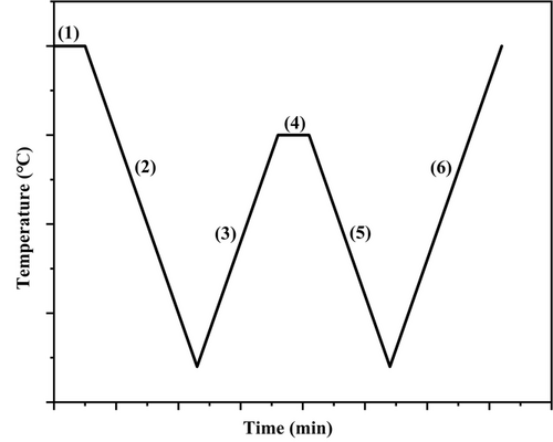
2.2 Calorimetry (DSC)
The employed differential scanning calorimeter (DSC) was a TA Instrument DSC Q20 equipped with a refrigerating cooling system RCS40. It was calibrated with Indium and it worked under a 50 mL min–1 flow of dry Nitrogen.
-
All blends were heated to high-temperature (200 °C, well above the melting point of the matrix) and kept at this temperature for 3 min to erase the thermal history.
-
The sample was cooled to 0°C, at a cooling rate of 10 °C min–1, to create a standard crystalline state.
-
Partial (or complete) melting of the sample was performed by heating at 10 °C min–1 to the SN temperatures (Ts) of the matrix.
-
Holding the sample at Ts for 5 min.
-
The sample was cooled to 0 °C at a cooling rate of 10 °C min–1. In this cooling scan, the effects of Ts on the crystallization of the matrix and dispersed phase are appreciated.
-
A final heating scan from 0 to 200 °C of the recrystallized sample was performed at a rate of 10 °C min–1. This scan will display any changes in the melting temperature of the matrix and dispersed phase caused by the SN treatment.
2.3 Scanning Electron Microscope (SEM)
The morphology of the cryogenically fractured surface of the different blends was investigated using a field-emission scanning electron microscope (Supra 40 VP model, Zeiss, Germany) at an accelerating voltage of 5 kV. The specimens were first cooled with liquid nitrogen and then fractured. A Polaron E5100 sputter coater was used to coat the sample with thin carbon layers.
3 Results and Discussion
3.1 Self-Nucleation of the Matrix and Non-Isothermal Crystallization of the Dispersed Phase in PB/Px Blends
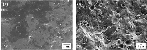
Figure 2 presents micrographs of the cryogenically fractured surface of PB/iPP and PB/PVDF blends. The blends exhibit a sea-island morphology in which the minor PB phase is present in the form of droplets or micro-domains dispersed in the semicrystalline iPP and PVDF matrices. The morphology of each blend confirms the immiscibility of the studied systems. Figure S1 (Supporting information) reports the droplet size distributions of the two blends, the size of the dispersed droplets changes with the matrix type. Based on the original calculation method proposed in Chandrasekar's work,[25] the sizes of dispersed micro-domains are reported in Table S1, Supporting Information. An increase in the diameter of the droplets is observed when changing the matrix from iPP to PVDF, which should be attributed to the differences in the melt-viscosity ratio and/or interfacial tension between the two components.[26]
Results of the DSC standard cooling and heating scans for neat and blended components are shown in Figure 3. The peak crystallization and melting temperatures of neat PB are 72.7 and 116.5 °C, corresponding to the crystallization and melting of Form II. The larger endothermic and exothermic peaks are attributed to the crystallization and melting of iPP and PVDF, instead. A minor decrease in crystallization temperature (Tc) for PB in both blends with respect to the neat polymer was observed in Figure 3a. In fact, this phenomenon was already observed by Wang et al.[27] who proposed that the nucleation of the finely dispersed PB droplets does not occur homogeneously, but at the interface with the iPP matrix, when the content of PB decreases below 25 wt.%. However, as the content of PB increases to 30 wt.% or more, the crystallization temperature of blended PB could be above that of neat PB, the reason for this being the migration of active heterogeneities from the iPP matrix to the PB phase during melt mixing. This explanation for blended systems are based on the previous works of Pracella et al.[28-30] It should be noted that the slight decrease in Tc for PB (≈1 °C), although close to the precision of the DSC measurement, can be thus attributed to a loss of nucleating impurities of the dispersed phase toward the matrix.
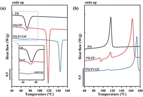
In the subsequent DSC heating scans of Figure 3b, a new melting peak at ≈92 °C appears in the PB/iPP blend, indicative of the formation of Form I’.[31] At a higher temperature, an exothermic signal is observed, indicating a recrystallization process, i.e., Form I’ crystals melt and recrystallize into Form II crystals. For PB/PVDF blend, the minor decrease of Tm for PB (≈6 °C) in comparison with the neat polymer should be still compatible with the melting of Form II, which crystallized at lower temperatures with respect to the neat PB.
Figure 4 shows DSC cooling and heating scans obtained after self-nucleating the iPP phase at different Ts values for the PB/iPP blend. This protocol can be used to study the effect of matrix crystallization on the dispersed phase. Possible changes in the thermal behavior of PB can be easily visualized.
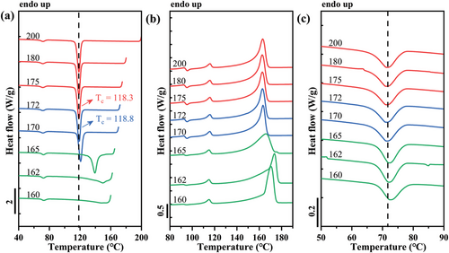
The employed seeding temperatures allowed us to observe all of the typical self-nucleation domains of the iPP phase, as suggested by Müller et al.[16, 32] By applying Ts in the range 175–200 °C to completely erase the crystalline thermal history, both crystallization and melting traces are unchanged, corresponding to Domain I. In this Domain, crystallization is dominated by heterogeneous nucleation produced by impurities or pre-existing nucleating heterogeneities. By lowering Ts to the range of 172–170 °C, a gradual increase in Tc values upon decreasing Ts is obtained, a behavior that corresponds to Domain II, indicating that a melt memory process is present. This additional nucleation occurs from the self-nuclei present in the non-isotropic melt.[24, 33] The beginning of Domain III is detected when a melting shoulder appears to the right of the main melting peak in the heating scan, as produced by the fusion of the unmolten crystals annealed during the holding time in step 3 of the SN thermal protocol (see Figure 4b).
In Figure 4c, the behavior of dispersed PB crystallization within the specific thermal protocol (SN) for iPP matrix in PB/iPP blend is reported. A slight increase in Tc of PB phase in the blend in the cooling run is found as well, indicating an increase in crystallization kinetics. However, no significant variations in the melting behavior of the PB phase are noticeable during the final heating scans. In fact, the phenomenon has been found in similar blend systems,[10, 34] in which the interaction of the two phases at the interface is proposed. Actually, epitaxy of PB with iPP has been reported in thin films.[21] A geometrical relationship between the lamellar thickness of the matrix and dispersed phases are required for epitaxial growth of one phase on top of the other.[19, 20, 35-39] In this case, surface-induced epitaxial crystallization has probably occurred in the PB/iPP blend, as suggested by the increased crystallization temperature of the PB dispersed phase when the Tc of the iPP matrix is increased via the self-nucleation protocol.
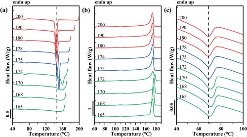
The effect of the self-nucleation on the PB and PVDF phases in the PB/PVDF blend is shown in Figure 5. As we described for the iPP phase in the PB/iPP blend, different SN domains for PVDF can also be highlighted, and are represented in different colors (red for Domain I, blue for Domain II, and green for Domain III) in Figure 5a,b. A slight shift toward higher temperatures of the crystallization peak of the PB phase in the blend can also be detected for Ts temperatures corresponding to Domain II, i.e., at 175 °C (See Figure 5c). This finding also suggests that PB nucleation occurs at the interface with the PVDF matrix. However, the existence of a specific epitaxial relationship between the two polymers is not demonstrated in the literature.
The Tc values of the matrix phases are reported in Figure 6a as a function of the matrix Ts values for both studied blends. The borders between the three characteristic domains are indicated as vertical lines. It is clear that no variation of Tc was found for the iPP and PVDF phases while in Domain I. On the contrary, a significant increase of Tc of both matrices are recorded in Domain II, meaning the crystallization kinetics of the matrix is greatly enhanced by the presence of self-nuclei.
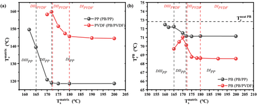
Figure 6b shows the parallel evolution of Tc of the dispersed PB phase as a function of the corresponding matrix Ts. For PB in these two blends, the increase in the crystallization kinetics starts from the SN Domain II of the corresponding matrix, due to the effect of the changing matrix Tc, causing the formation of thicker lamellar crystals in the matrix phase, which in turn favors PB droplet nucleation at the interface. The Tc of the dispersed phase continues to increase in the SN Domain III of the iPP phase for PB/iPP blend, but starts to decrease in the Domain III of the PVDF phase for PB/PVDF blend. Even though there is a decrease in the Tc in Domain III, it remains always higher than the Tc recorded in Domain I. Furthermore, the Tc of PB in the PB/iPP blend is always higher than that of PB in the PB/PVDF blend, independently of the considered SN Domain. Considering that the average size of PB droplets is 0.24 µm in iPP matrix and 1.37 µm in PVDF matrix, a lower Tc of PB in Domain I for PB/iPP blend would be expected, due to a more probable loss of nucleating impurities. However, what happens in practice is that the Tc of PB is always higher in the case of PB/iPP with respect to PB/PVDF blends. This finding can be attributed to the higher nucleating efficiency of iPP surface toward PB, likely due to the known epitaxial relationship,[21] while for PVDF, an epitaxial mechanism is either lacking or the crystallographic mismatch between the two structures is more significant than that existing for the PB/iPP system. Moreover, the Tc of PB in the blends is lower than that of neat PB indicated by the horizontal line in Figure 6b (the complete self-nucleation behavior of the neat PB is reported in Figure S2, Supporting Information), suggesting that some nucleating impurities of neat PB are transferred to the matrices during melt blending.
3.2 Self-Nucleation of the Matrix and Non-Isothermal Crystallization of the Dispersed Phase in PCL/Px Blends
SEM micrographs of the cryofractured PCL/PB and PCL/PVDF blends are shown in Figure 7, while the blends of PCL with the other matrices are reported in Figure S3 (Supporting Information). Similar to the PB/Px case, the micrographs reveal a sea-island morphology, typical of immiscible blends. The histograms of the size distribution of PCL droplets in the different blends are shown in Figure S4 (Supporting Information), while the average number, volume diameter (dn and dv), and dispersity (D) are reported in Table S2 (Supporting Information). It is noteworthy that a wide variety of droplet sizes is produced, as changing the matrix in the blends, the average size of droplets increased from 0.16 to 16.22 µm for PVDF and PBS, respectively. The average size is instead more similar and in the range of 0.6–1.8 µm for PCL/iPP, PCL/PB, and PCL/HDPE blends.
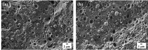
Figure 8 shows the DSC cooling and heating curves of neat PCL and PCL/Px blends obtained at 10 °C min–1. The peak crystallization and melting temperatures of neat PCL are 31.8 and 55.8 °C, respectively. For blended systems, the larger peaks are always attributed to the crystallization and melting of the matrix, accordingly to the blend composition. Comparing the crystallization peak of PCL in neat and blended systems, an increase in the PCL Tc value (reported in Figure 8a) is highlighted in all the blends except for PCL/PVDF and PCL/PB (≈1 °C below Tc of neat PCL). The increased nucleation rate of PCL droplets in the different blends can be attributed to interfacial nucleation with various efficiencies or to the migration of active nucleating heterogeneities from the matrix to the PCL phase.[10, 28-30, 34, 40] To distinguish between the two effects, the self-nucleation protocol of the matrix phase will be employed in the following. The decreased Tc of PCL/PVDF can only be attributed to a loss of nucleating impurities by the dispersed phase toward the matrix, while the PVDF surface can still act as a nucleating substrate, although with low efficiency.
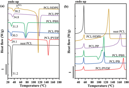
Figure S5a (Supporting Information) reports the DSC cooling scans after self-nucleation of the neat PCL at the indicated Ts, while Figure S5b (Supporting Information) shows the subsequent heating scans. In neat PCL and at Ts higher than 80 °C, no appreciable changes in the crystallization peak are observed, which is indicative of SN Domain I. Starting from 80 °C down to a low Ts of 60 °C, a clear increase in the crystallization temperature is recorded. In this range of temperatures, the thermal treatment applied during SN creates self-nuclei in PCL, which is typical of Domain II. Below 60 °C, more crystals undergo annealing and lamellar thickening during self-nucleation, and changes in the final heating scans occur. In particular, a small melting peak at temperatures higher than the main melting peak, as typical of SN Domain III, is not observed in this case. Instead, the full melting peak slightly shifts to higher temperatures with decreasing Ts.
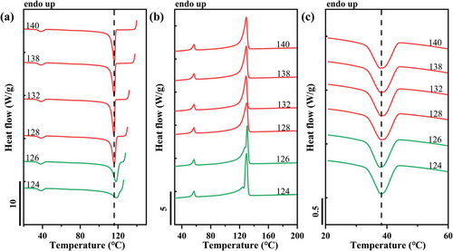
Figure 9 presents DSC cooling and heating scans after self-nucleation of the HDPE matrix phase within the PCL/HDPE blend at the indicated Ts. At Ts > 138 °C, both crystallization and melting of the HDPE phase are invariant. In this temperature range of Domain I, the crystallization behavior is controlled only by high-temperature-resistant nucleating heterogeneities. Domain III starts at Ts values ≤ 128 °C. In this temperature range, the Tc is increasing with the decrease in Ts, however, the sample is only partially molten, and the unmolten HDPE crystal fragments experience annealing and become thicker, resulting in a second melting peak at higher temperatures in the final heating scan (Figure 9b). This indicates that, with the adopted self-nucleation temperature window of 2 °C, no Domain II can be highlighted, and a direct transition from Domain I to Domain III is observed, as typical for HDPE. Moreover, in the studied Ts temperature range, there is a negligible variation in the crystallization behavior of PCL droplets after SN of HDPE matrix (Figure 9c). However, it is noteworthy that the crystallization temperature of PCL droplets in the PCL/HDPE blend is ≈6 °C higher than that of the isotropic melt of neat PCL.
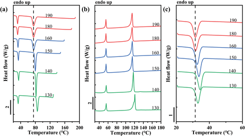
Another example is reported in Figure 10, which shows the DSC cooling and heating scans after self-nucleation of the PB phase within the PCL/PB blend. As we described previously, the three characteristic SN domains are distinguished depending on the Ts range: red for Domain I (190–180 °C), blue for Domain II (180–150 °C), and green for Domain III (150–130 °C) as proposed by Müller et al.[16, 32] The crystallization behavior of dispersed PCL during SN of PB phase in PCL/PB blend is analogous to that of dispersed PB in PVDF or iPP matrix. More specifically, the crystallization peak of PCL in the PCL/PB blend moves toward higher temperatures, as the Ts of PB decreases (Figure 10c). For the lowest Ts values employed, a slight decrease of PCL Tc is observed. We note that the maximum increase in PCL crystallization temperature is ≈3 °C, thus revealing a minor surface nucleation effect in comparison to the HDPE substrate (≈7 °C). Analogous phenomena with self-nucleation of other matrices within PCL/iPP, PCL/PVDF, and PCL/PBS blends are shown in Figures S6–S8 (Supporting Information), respectively. All these systems, except for the PCL/HDPE blend, show a relationship between the dispersed phase's Tc and the matrix's self-nucleation temperature. The trend of increasing crystallization temperature of the dispersed phase with decreasing Ts of the matrix is thus believed to be a general observation for double semicrystalline immiscible blends, being observed for six systems in the present work and one blend in previous literature.[10] This relationship strongly suggests the role of the interface in the nucleation of dispersed droplets. Notably, by comparing Figures 10 and Figure 10, and Figures S6–S8 (Supporting Information), distinct nucleation effects, i.e., different PCL Tc, are exhibited by the different matrices, pointing toward a certain nucleation efficiency scale between the various polymeric interfaces.
The self-nucleation effect of the matrix on PCL crystallization in the various blends is better grasped with the help of Figure 11. The self-nucleation of neat PCL is also reported, for the sake of comparison. An initial invariance of PCL crystallization temperature with Ts in Domain I of the matrix is observed for all the investigated systems. Then a typical increase of PCL Tc with decreasing Ts is clearly identified for several systems, although the extent of the variation is highly matrix-dependent. Such enhancement usually occurs within Domain II of the considered matrix, where the increase in Tc of the matrix corresponds to thicker lamellae as a nucleating template (see the indicated domains of HDPE and PB systems as an example). Interestingly, lower Ts values (in Domain III) might lead to lower PCL Tc in some systems. This observation is interpreted as the existence of a maximum lamellar thickness, due to the lower lamellar thickening rate with decreasing matrix Ts.
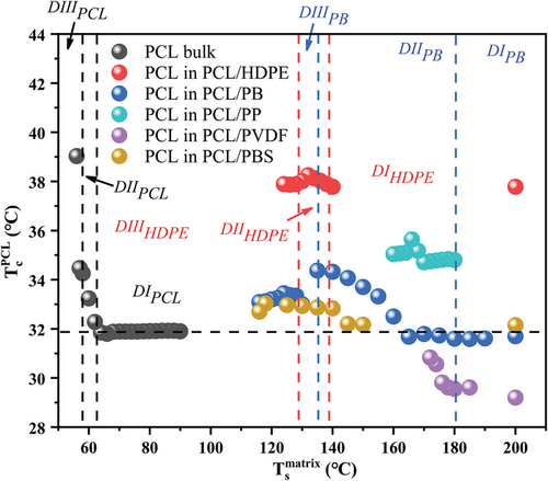
The data in Figure 11 also reveal a clear nucleating efficiency scale of the different matrices. In particular, considering for each blend the maximum PCL Tc, the nucleating efficiency decreases in the order: HDPE>iPP>PB>PBS>PVDF. Notably, the crystallization temperature of PCL/HDPE is higher than the one recorded for neat PCL self-nucleated at Ts,ideal, i.e., at the lowest temperature of Domain II. This implies that, according to Fillon et al. nucleating efficiency scale,[41, 42] the efficiency value of HDPE nucleating PCL is above 100%, i.e., it is a case of supernucleation.[43-45] Such high nucleating efficiency is most probably due to the known excellent crystallographic matching between PCL and HDPE, already demonstrated by Yan et al. in thin polymer films.[22] The epitaxial crystallization mechanism also explains the second ranking of iPP surfaces, as a certain degree of matching between some given PCL and iPP crystal planes was also reported.[24] In fact, our nucleation efficiency observation, i.e., HDPE>iPP, is in agreement with previous literature on thin films.[24] For the rest of the substrates, no specific epitaxial relationship is known. However, the matrix self-nucleation methods clearly prove the occurrence of surface nucleation, whose efficiency can be attributed to a poorer lattice matching with PCL or simply non-specific PCL/substrate interactions. It is worth noting that, for the PCL/PVDF blend, although nucleation clearly occurs at the surface (see the increase of PCL Tc with decreasing Ts of PVDF), the crystallization temperature of the dispersed PCL phase is lower than that of the neat polymer. This can only indicate that some nucleating heterogeneities are transferred from the PCL phase to the PVDF matrix domain during melt mixing, similar to what occurred for the PB-based blends.
To offer a different view of the surface nucleation phenomenon, the Tc values for the dispersed phase are reported in Figure 12 as a function of the matrix Tc in both PB and PCL-based blends. For practically all the systems, the Tc of PB (Figure 12a) or of PCL (Figure 12b) increases linearly with the crystallization temperature of the various matrices, which in turn is increased by the effect of self-nucleation. Given that the lamellar thickness of the matrix crystals is defined by the undercooling, i.e., by the crystallization temperature, we proposed that the relationship between the two Tc represented in Figure 12 parallels the increase of droplets nucleation kinetics when in contact with thicker lamellae of the matrix polymer. We note that the increased lamellar thickness for self-nucleated iPP has been demonstrated already for the case of HDPE/iPP blends.[10] The reason behind the enhanced crystallization kinetics of the dispersed phase when increasing the crystal dimension of the matrix is tentatively ascribed to a template nucleation model.[35] Thicker lamellae offer a better nucleating substrate for forming dispersed phase nuclei, since the crystallizing polymer chain segments are less likely in contact with the amorphous part of the matrix phase morphology, thus experiencing a lower energy penalty and hence a lower nucleation energy barrier. A similar concept has been put forward in our work in the case of cross-nucleation between polymorphs of PB.[38]
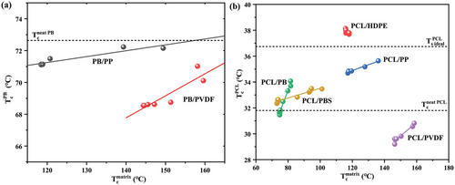
Also from the plots of Figure 12, the different nucleating efficiency of the various polymer matrices can be easily captured, by judging the maximum Tc of each series. The comparison with the crystallization of neat polymers is also straightforward: it can be seen that both PVDF and iPP have an anti-nucleation effect on PB dispersed phase, due to impurity transfer to the matrices. The same is true for the PVDF matrix in PCL/PVDF blend, while HDPE substrate in PCL/HDPE blends displays a super-nucleation effect, possibly due to the good epitaxial matching, as previously discussed.[22, 23]
4 Conclusion
In the present work it was reported that, by changing the polymer matrix crystalline state in immiscible blends through the self-nucleation technique, a variation in the crystallization kinetics of PB and PCL dispersed phases was obtained. This demonstrates that nucleation of the dispersed phase droplets occurs at the interface with the matrix phase for a variety of double semicrystalline immiscible polymer blends. Interestingly, the different semicrystalline matrices exhibit distinct nucleation efficiencies towards the dispersed droplet phases, either PB or PCL. In particular, the blend systems displaying the highest nucleating efficiency are those for which epitaxial crystallization of the two polymers is known to occur, i.e., HDPE/PCL and PB/iPP. The adopted method is very versatile for proving the surface nucleation of polymer droplets in immiscible blends. Given the body of examples provided by the present work, the phenomenon is believed to be general, at least for double semicrystalline polymer blends.
Acknowledgements
W.W. thanks the China Scholarship Council (CSC) for funding his Ph.D scholarship. The authors acknowledge the financial support from the BIODEST project; this project has received funding from the European Union's Horizon 2020 research and innovation program under the Marie Skłodowska-Curie Grant Agreement No. 778092. G.L. and A.J.M. acknowledge the financial support from the National Key R&D Program of China (2017YFE0117800).
Open Access Funding provided by Universita degli Studi di Genova within the CRUI-CARE Agreement.
Conflict of Interest
The authors declare no conflict of interest.
Open Research
Data Availability Statement
The data that support the findings of this study are available from the corresponding author upon reasonable request.


