B1 transmission-field inhomogeneity and enhancement ratio errors in dynamic contrast-enhanced MRI (DCE-MRI) of the breast at 3T
Abstract
Purpose:
To quantify B1 transmission-field inhomogeneity in breast imaging of normal volunteers at 3T using 3D T1-weighted spoiled gradient echo and to assess the resulting errors in enhancement ratio (ER) measured in dynamic contrast-enhanced MRI (DCE-MRI) studies of the breast.
Materials and Methods:
A total of 25 volunteers underwent breast imaging at 3T and the B1 transmission-fields were mapped. Gel phantoms that simulate pre- and postcontrast breast tissue T1 were developed. The effects of B1-field inhomogeneity on ER, as measured using a 3D spoiled gradient echo sequence, were investigated by computer simulation and experiments on gel phantoms.
Results:
It was observed that by using the patient orientation and MR scanner employed in this study, the B1 transmission-field field is always reduced toward the volunteer's right side. The median B1-field in the right breast is reduced around 40% of the expected B1-field. For some volunteers the amplitude was reduced by more than 50%. Computer simulation and experiment showed that a reduction in B1-field decreases ER. This reduction increases with both B1-field error and contrast agent uptake.
Conclusion:
B1 transmission-field inhomogeneity is a critical issue in breast imaging at 3T and causes errors in quantifying ER. These errors would be sufficient to reduce the conspicuity of a malignant lesion and could result in reduced sensitivity for cancer detection. J. Magn. Reson. Imaging 2010;31:234–239. © 2009 Wiley-Liss, Inc.
DYNAMIC CONTRAST-ENHANCED breast MRI (DCE-MRI) is considered to be the most sensitive imaging technique in the diagnosis of breast cancer (1, 2). The technique can also be used to characterize breast tissue by monitoring T1-weighted signal enhancement after a bolus administration of an intravenous low molecular-weight paramagnetic contrast agent (CA). Breast cancers have abnormal microvascular properties because of their increased vascular capillary density and permeability so that they show increased signal enhancement compared to normal tissue (3, 4).
 (1)
(1)In the United Kingdom, breast DCE-MRI is typically performed at 1.5T using a 3D T1-weighted spoiled gradient echo sequence (e.g., flip angle [α] = 35°, repetition time [TR] = 10–16 msec, echo time [TE] = 4.2 msec [water and fat signals in-phase], and imaging time per repetition = 90 seconds) (10). 3T clinical MRI machines have been introduced. The main advantage of a higher-field MRI scanner is the increase in signal-to-noise ratio (SNR). This increase can be traded off to improve the spatial and/or temporal resolution of a dynamic imaging study. The improvement in morphological detail and temporal resolution can be manipulated to increase both the sensitivity and specificity of DCE-MRI. This may lead to an increase in the accuracy of breast MRI cancer diagnosis and reduce the number of unnecessary biopsies (11). Furthermore, acquisition of functional information at 3T with smaller voxels may improve the reproducibility of analysis techniques.
However, a significant drawback at high field is the increase in B1 transmission-field inhomogeneity across the field-of-view (FOV), which is particularly marked in breast imaging (12). This problem is caused by the off-center positioning of the patient's torso within the transmitting whole-body radiofrequency (RF) birdcage coil giving rise to unequal loading effects, and by a standing RF wave effect accentuated by the short RF quarter-wavelength at 3T. Both of these effects are more pronounced at higher field strengths (13, 14).
Kuhl et al (12) have shown that the signal enhancement of breast lesions is lower at 3T relative to the enhancement measured at 1.5T. A significant inhomogeneity of the B1-field across the two breasts was observed (a right-to-left difference of a factor of 2 was reported). They associate the resulting errors in flip angle (due to the B1 inhomogeneity) to a reduced T1 weighting and hence to reduced signal enhancement. Kuhl et al (11, 12) suggest that in locations of very low B1-field there would be no enhancement observed at all. As such enhancement measurements of breast lesions obtained at 3T may be insufficient to establish a useful diagnosis for some patients and result in malignant lesions being overlooked. This issue is a significant setback to the use of clinical breast MRI at 3T.
The aim of this study was to quantify B1 transmission-field inhomogeneity in breast imaging of normal volunteers at 3T using a 3D T1-weighted spoiled gradient echo pulse sequence and to assess the resulting errors in ERs in DCE-MRI studies. We employed this sequence because it is commonly used for breast DCE-MRI in the United Kingdom (10). In this work, ERs in the presence of B1-field inhomogeneity were assessed using computer simulation and experiments on T1 gel phantoms.
MATERIALS AND METHODS
In Vivo B1 Transmission-Field Mapping
After approval by the local ethics committee and informed consent 25 healthy female volunteers (age = 43 ± 11 years, body mass index [BMI] = 24.7 ± 4.0 kg m−2) were recruited. They were imaged axially in the prone position and head first with a seven-channel SENSE breast coil (Philips Healthcare, Best, the Netherlands). The axial orientation was chosen as it is commonly used in MR mammography and also a large B1 transmission-field variation is expected from left to right (12).
B1 transmission-field mapping was performed using 3D actual flip-angle imaging (AFI) sequence (14), which is one of the most accurate and rapid in vivo B1 mappings available. This technique measures the B1-field amplitude by acquiring images using a gradient echo pulse sequence consisting of two identical RF pulses but with different TRs (TR1/TR2 = 30/150 msec, TE = 2.4 msec, α = 60°, matrix size =128 × 128, FOV = 400 × 400 mm, slice thickness = 12 mm, and number of slices = 20). Using this mapping, the amplitude of B1-field was estimated for each voxel by measuring the αs generated in the subject relative to the expected α expressed as a percentage. A combination of α and TRs used in this study were chosen to optimize the accuracy of the B1-field measured using this particular technique (14).
B1-field profiles were plotted on B1 maps from right to left to quantify its variation across the FOV. Using the center slice of the 3D stack, an ROI approximately the size of two-thirds of the breast area was positioned over each breast with ImageJ (National Institute of Health, Bethesda, MD, USA). This allowed measurement of B1 (left), B1 (right), and B1 (difference). Data analysis was performed using SigmaPlot 11.0 (Systat Software, Inc., San Jose, CA, USA).
As an additional measure of magnet loading an estimate of the volunteers' cross sectional area was made. This was performed by making measurements on the center slice of the acquisition image. The area was estimated by measuring the maximum left-right distance of the thorax (W), the depth from the sternum to the vertebrae (D), the length from the nipple to the chest wall (N), and the width of the breast at the chest wall (B). The area was calculated by summing the thorax area (W × D) and the left and right breast areas (N × B). Since not all volunteers body area were fully covered by the standard FOV used in the scanning, only 17 volunteers were included in this investigation.
Simulation of B1 Transmission-Field Inhomogeneity and Enhancement Ratio
 (2)
(2)To simulate the effect of B1 transmission-field inhomogeneity on ER, an adjustable and uniform α across a FOV was required, so that all gel phantoms were subject to the same condition. Hence, 3D T1-weighted spoiled gradient echo imaging (α = 35°, TR/TE = 10/2.3 msec, matrix size = 256 × 256, FOV = 200 × 200 mm, slice thickness = 2 mm, and number of slices = 30) was performed using a quadrature transmit-receive head coil, which produces relatively the most homogeneous B1 transmission-field across an FOV. The nominal α of 35° was chosen because it is a commonly used flip angle in clinical DCE-MRI in the United Kingdom for the range of TR used (10) and it produces a good linear contrast response and sufficient SNR over the range of T1 values found in breast tissues.
To simulate the effect of B1-field inhomogeneity, α was changed to 17°, 26°, 44°, and 53°, which represent 49%, 74%, 126%, and 151% of the desired B1. These values were chosen to cover a wide range of B1 inhomogeneity. The lower limit corresponds with the minimum value expected for this scanner and field strength (12). Assuming that the native T1 (T10) of ductal tissue is approximately 1300 msec at 3T (17), which matches the T1 value of one of our gel phantoms, the ER was calculated for each phantom at each α using Eq. [ 1]. By assuming that the gel with the longest T1 represents the precontrast tissue and that the postcontrast tissue is represented by of each of the shorter T1 phantoms, the difference in relaxation rate (ΔR1) (ΔR1 = [1/T1] – [1/T10]), which is assumed to be directly proportional to CA uptake (18), was calculated. This approach was also used by Hoffman et al (19).
 (3)
(3)B1-field maps (TR1/TR2 = 30/150 msec, TE = 2.4 msec, α = 60°, matrix size = 256 × 256, FOV = 200 × 200 mm, slice thickness = 1.5 mm, and number of slices = 20) were performed as a check on the homogeneity of B1 transmission-field for gel phantom experiment.
RESULTS
In Vivo B1 Transmission-Field Mapping
An example of a typical B1 transmission-field map and profile produced on a volunteer is shown in Fig. 1a and b. It can be observed that the B1-field is reduced to about one-half that of the right breast.
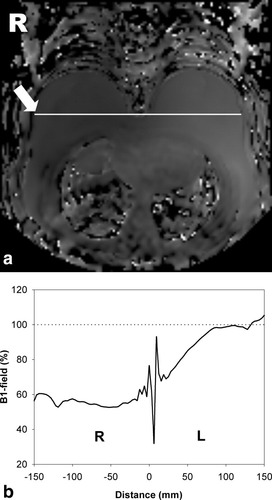
a: Typical B1 map produced on a volunteer. b: The profile of B1-field measured across the right (R) and left (L) breast shown by the arrow in (a).
The average B1-field measured on the left and right breast on 25 volunteers is shown in Fig. 2a. It was found that the B1 is reduced significantly in the right breast for all the volunteers. The median B1-field is around 60% of the nominal B1. For some volunteers the amplitude was reduced by more than 50%. Minimal alteration was observed for the left breast but the amplitude is reduced toward the center of the body as shown in Fig. 1b.
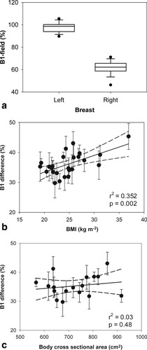
a: Box-plot showing mean B1 field in the left and right breasts. The boundary of the box indicates the 25th and 75th percentile, the line within the box marks the median. The error bars represent the 90th and 10th percentiles and the black dots indicate the outliers. b: The relationship between B1-field difference of the left and right breast and BMI; the error bars show the SDs, the straight line is linear regression, and the dotted lines are 95% confidence intervals. c: The relationship between B1-field difference and body cross-sectional area.
A scatter-plot of the difference between B1 transmission-field measured on the left and right breast vs. BMI is shown in Fig. 2b. In general, larger reductions of the B1-field field on the right breast were observed for volunteers with higher BMI. The linear regression line and 95% confidence limits are shown (Pearson's r2 = 0.352; P = 0.002). The relationship between B1 field and cross sectional area of the thorax and breast is shown in Fig. 2c. A linear regression gives Pearson's r2 = 0.03 and P = 0.48. There is a larger B1-field variation between left breast axilla and right breast close to the sternum than across the middle of both of the breasts. This was measured to be 47% (median).
Simulation of B1 Transmission-Field Inhomogeneity and ER
The T1 values (mean ± SD) measured using the IR sequence on the gel phantoms developed are: 91 ± 1, 185 ± 3, 378 ± 6, 577 ± 7, 822 ± 8, 988 ± 6, and 1301 ± 11 msec.
B1-field map and profile measured on gel phantoms are shown in Fig. 3a and b, respectively. By using a transmit-receive head coil, an acceptable homogeneous B1-field in the area occupied by the gel phantoms was produced. Hence, it provides a sufficient accuracy to simulate B1-inhomogeneity using different α on gel phantoms.
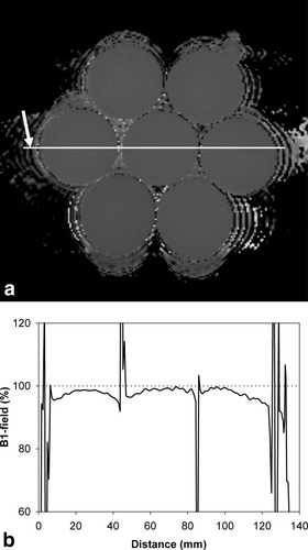
a: Typical B1-field map produced on gel phantoms. b: The profile plot of B1-field measured across the phantoms as shown by the arrow in (a).
ER vs. ΔR1 for five simulated B1-fields is shown in Fig. 4. Here, the gel with the longest T1 was used as the precontrast baseline (hence T10 = 1301 msec). From computer simulation and experiment, it can be observed that ER significantly decreases with the reduction of B1-field and increases (with a lesser extent) with B1-field higher than the optimal value. Figure 4 also shows that the error in ER increases with ΔR1 and thus CA uptake (ΔR1 was assumed to be directly proportional to CA uptake).
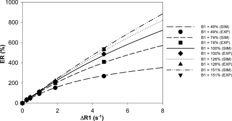
Enhancement ratio (ER) as a function of changes in relaxation rate (ΔR1) for different levels of B1-field inhomogeneity using computer simulation (SIM) and experiment on phantoms (EXP). Only six of the phantoms are shown. The errors for experimental data are not shown (SD <3% of the ER).
DISCUSSION
We have shown that the B1 transmission-field is always reduced toward the right side of the body when 3D T1-weighted spoiled gradient echo images were obtained using the standard manufacturer settings of our 3T MR scanner (Philips Achieva X series) and patient positioning technique (prone and head-first). Therefore, the right breast will always receive less B1-field compared to the left breast. This problem will cause reduced intensity on the MR images obtained. It was shown that for some subjects, the B1-field could be reduced to less than 50% of the expected level. This result supports the observations of Kuhl et al (12) who reported the same right-to-left B1-field reduction on 2D T1-weighted spoiled gradient echo. The authors found that B1-field is consistently reduced in the right breast to about one-half of the field in the left breast. However, our results show that the degree of reduction is dependent on the patient's body size—the B1-field inhomogeneity effect becomes more prominent in subjects with large body size (increased BMI). However, the B1-field difference is only weakly correlated with BMI (r2 = 0.352; P = 0.002) (Fig. 2b) and with the body cross-sectional area (Pearson's r2 = 0.03; P = 0.48) (Fig. 2c).
In order to analytically investigate the claim made by Kuhl et al (12) that ER can be reduced by a variable degree caused by B1-field inhomogeneity at 3T, we simulated the effects of the inhomogeneity on ER using computer simulation and experiment on T1 gel phantoms. We demonstrate that ER is influenced by the B1-field inhomogeneity where a reduction in B1-field reduces ER. It was also found that this effect increases with both B1-field error and CA uptake (represented by ΔR1).
It has been reported that by using 3D spoiled gradient echo at 1T, the range of ΔR1 for malignant tissue can be up to 7.5 seconds−1 (18). In the presence of a 50% inhomogeneity at this ΔR1, the ER will be reduced by 50%. Higher B1-field reduction and ΔR1 are possible in clinical breast DCE-MRI at 3T. This might explain the claim made by Kuhl et al (12) that no enhancement may be measured in an area of very low B1-field where contrast is determined by proton-density, not by T1 weighting.
Our results also suggest that the use of α larger than 35° (with TR of 10 msec) does not greatly alter the ER. However while the use of a larger α might be useful to reduce the errors in ER, it may not be practical at 3T due to a resulting excessive RF specific absorption rate (SAR). Furthermore, for bilateral tumors and staging of the other breast direct comparison of signal intensity and signal enhancement in the left and right breast is required.
In addition to the simple enhancement index used in this article, other indices have been proposed (18, 20). The variation in enhancement index with B1 transmit inhomogeneity arises because of the nonlinearity of the signal response curves with R1, which varies with pulse angle, so that errors are expected with any index of enhancement.
In conclusion, 3T MRI is rapidly becoming the new standard in routine clinical imaging. High-field systems offer a great potential in improving the sensitivity and specificity of breast cancer imaging. However, increasing the magnetic field to 3T will increase the B1 transmission-field inhomogeneity effects, which will produce errors in any method that attempts to quantify the enhancement of a tumor including ER measurement. These errors increase with both B1-field error and CA uptake. Therefore, further studies must be done to find a practical and effective way to minimize this problem so that 3T MR scanners can be used efficiently in clinical breast DCE-MRI.
Acknowledgements
We thank Philips Healthcare for their support on this work, particularly Dr. Matthew Clemence and Mr. Wim M. Prins.


