An Inertia Correction Scheme for Hydrodynamic Lubrication Problems
ABSTRACT
A new simplified numerical approach for accurately calculating the bearing pressure distribution in one-dimensional hydrodynamic lubrication problems, particularly including convective fluid inertia and film discontinuities, is presented. The method proposes a simple inertia correction scheme using a non-uniform finite difference method based on the Reynolds equation. Two possible approaches to estimating the pressure correction due to fluid inertia are discussed: the Bernoulli effect and the averaged inertia. The results obtained for various operating conditions, especially by employing the average fluid inertia method, are found to be almost identical to the full Navier–Stokes (CFD) results and are more generalized. The proposed method may provide extremely fast calculation with accuracy.
1 Introduction
The nature of lubrication in fact is a complex fluid flow problem, but in practice, simplified assumptions are used due to hydrodynamic bearings being one of the most basic machine elements. Therefore, Reynolds equations (RE) are preferred over Navier–Stokes equations (NSE) in hydrodynamic lubrication theory with assumptions such as neglected inertia effect, infinitely wide/narrow bearing theories etc. However, the neglect of the inertia effect causes the pressure distribution, which is the most important parameter in slider bearings, to be miscalculated at a noticeable level under specific configurations, especially with sudden changes in film thickness or large operating clearance. [Correction added on 10 March 2025, after first online publication: In the first paragraph of the Introduction section, the terms “long/short” have been changed to “wide/narrow” in this version.]
Thus, the inertia effect began to be investigated analytically for continuous basic film geometries near the 1950s. As with similar methods used in the current study: Extending the boundary layer integral approach, Slezkin and Targ proposed an analytical approximation method by averaging the inertia terms in NSE across the fluid film [1]. Kahlert showed that inertial effects can also be included in classical lubrication theory by using the inertia terms of NSE and RE together with an iterative (perturbation) procedure analytically [2]. In addition to these, Constantinescu focused on comprehensive analytical solutions and presented empirically consistent formulations for one-dimensional bearing pressure calculation, including inertia correction [3]. All the mentioned studies revealed that the pressure correction due to the inertia effect is proportional to ρum2, like the dynamic pressure term in the Bernoulli equation (BE).
The most recent study focusing especially on inertia-pressure correction for film discontinuities was done by Arghir, Alsayed, and Nicolas probably unaware of the mentioned literature above in the early 2000s. Using a similar method to Kahlert's iterative procedure, they solved RE directly combining with the generalized BE to include approximate inertia effect by finite volume method. The pressure correction is somewhat overestimated in [4], since BE depends only on the averaged fluid velocity (um) for the one-dimensional case. Therefore, the authors added a pressure correction term to the generalized BE that needs to be predetermined experimentally or numerically. The present study, however, directly addresses this long-standing issue successfully delivers an improved soliton.
Inertial effects are particularly important in discontinuous film geometries, such as in Rayleigh step, grooved, and textured bearings. When more accurate pressure calculation is required, as in thermohydrodynamic lubrication (THD) and so forth problems, computational fluid dynamics (CFD) analysis is almost a necessity. Because in this case, the lubrication problem needs to be calculated with 2D or 3D full-NSE. In this manner, Dobrica and Fillon compared RE and NSE solutions for THD in Rayleigh step bearing (RSB) and concluded that RE overestimates load carrying-capacity up to 18% relative to NSE for some specific bearing configurations. They showed that this was due to the pressure drop right after the discontinuity line caused by the neglected inertia effect in RE [5]. The same authors also extended their work on the inertia effect in textured film configurations and discussed the validity of using RE in textured sliders. They concluded that the RE can be applied in textured sliders with sufficiently large texture aspect ratio and small Reynolds number [6]. Similar to these studies, Vakilian, Nassab, and Kheirandish numerically investigated the THD characteristics of RSBs under different configurations using CFD technique, and their findings indicate that inertia has a greater effect on pressure calculation than temperature [7]. Ogata and Sugimura offered an equivalent clearance height method to solve the RE for discontinuous geometries where the RE method does not predict accurate velocity profiles in discontinuity. They aimed to remove the discontinuity of velocity components at the step for THD calculations without considering the inertia effect. Since their method cannot cover the sudden pressure change at discontinuous regions, it seems to be applicable only for a limited range of bearing configurations with minimal inertia effect [8].
Previous studies highlight that using the complex NSE (or CFD) method for accuracy in basic lubrication problems complicates even the simplest problem. Thus, relatively simpler, and more accurate computational methods are still needed to include the inertia effects. In this study, a new numerical approach that is both straightforward and incorporates pressure drop into the calculations has been introduced. With this method, the bearing pressure on a discontinuous film can be calculated accurately and easily by synthesizing the methods in the above studies. First, a direct numerical solution method for RE is proposed by separating the definition of the total pressure term into with and without inertia terms. Then, two possible calculation methods for the pressure term with inertia, especially in geometries with film discontinuities, are discussed and compared with the aforementioned studies.
2 Material and Methods
2.1 Theoretical Model
RE allows the pressure distribution to be calculated directly depending on the film thickness profile h(x) and can be solved either analytically for some simple geometries or numerically for complex geometries. Although this form of the equation offers relatively sufficient accuracy and ease for bearing design, it cannot capture inertia effects and is also invalid in the discontinuous film region (in principle dh/dx→∞). [Correction added on 10 March 2025, after first online publication: In section 2.1 – Theoretical Model, the term “long” have been changed to “wide” in this version.]
2.2 1D Non-Uniform FDM Formulation for Film Discontinuities
Uniform grid is widely preferred in the central finite difference method (FDM) because it is simple in practice and accepted to provide second-order accuracy. However, when evaluated from a physical perspective, the numerical solution of the problems does not present a uniformly distributed discretization error as expected. Because the truncation error depends not only on the grid spacing but also on the derivative of the variables in Taylor expansion [9]. In essence, the actual error depends on the nature of the solution function and thus, a solution with rational non-uniform (NU) grid seems more reasonable.
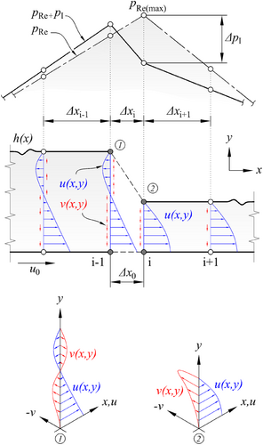
Bearing geometries with film discontinuities such as RSB, presented in Figures 1 and 3, are a very physical example of this NU-case. The fluid velocity and pressure distribution along the RSB length are in a continuous form in the continuous zones but change suddenly only for a very small segment (≈L × 10−2) in the vicinity of the discontinuity. The inertia forces are close to zero on both continuous zones (since h = constant, dh/dx = 0) and are concentrated only in the vicinity of the step. This gives a hint that discontinuities such as those in RSB geometry may be modeled as a continuous, “virtual-grid” that is numerically close to zero spaced (∆x0 → 0) in NU-FDM. In fact, physically two different film thickness values are located at the same x-coordinate on the discontinuity line and numerically choosing ∆x0 → 0 to model the discontinuity seems to cause the phenomenon of dh/dx → ∞ in the right-hand side of the RE, in Equation (5). Additionally, since the classical Reynolds theory applies only to continuous domains, the pressure and flow rate at both points of the discontinuity must be equal to ensure pressure continuity at the step in the case of neglected inertia.
Through this simple approach, the choice of ∆x0 → 0, which appears to be a problem mathematically, becomes a simple and useful tool for modeling discontinuity in terms of numerical method. For example, the RSB can be modeled as only three grids (four nodes), considering two continuous and one discontinuous domain with ∆x0 ≤ O(L × 10−3), and then the NU-FDM equation for pressure distribution calculation (6) can be easily solved with full accuracy as a 4 × 4 equation system by direct matrix method.
2.3 Implementing the Inertia Correction Scheme
2.4 Using Bernoulli Equation for Inertia Correction
The correction factor (α) must be determined for each discontinuous bearing geometry of different sizes, and if there are steps in different successive configurations such as grooves, determining a generalized correction factor would not be an easy task. Although the BE method is quite easy to apply, it always returns a positive value since it depends on the average velocity (um), and consequently this method can only model the pressure drop in discontinuity. However, in some configurations (e.g., inclined bearing), pressure rise due to inertia is also observed as shown in Figure 6. Such a calculation cannot be achieved with the BE method.
2.5 Using the Inertia Term in Navier–Stokes Equation for Inertia Correction
For a more generalized approach than the BE method mentioned above, the second novel method is to directly calculate the inertia effect numerically using the inertia term in the Navier–Stokes Equation (1). Assuming that the sudden velocity change at the discontinuity occurs in a very narrow length (see Figures 3 and 4), the discontinuity can be modeled at points ① and ② as shown in Figure 1. The velocity profiles required for the inertia term can simply be calculated numerically using Equations (3) and (4), as they depend on the film thickness.
Using Equations (3) and (4), the velocity components u and v can be calculated accurately for any continuous bearing geometry. However, depending on the pre-defined virtual-grid value ∆x0 ≤ O(L × 10−3) to model the discontinuity with NU-FDM, the numerical values of the v-term are calculated as amplified since the v-term depends on the gradient of u and again ∂u/∂x → ∞ phenomenon occurs at the virtual-grid. Nonetheless, these amplified values of ∂u/∂x and the v-term are numerically compensated by dx multiplier in numerical integration procedure. It can be observed that the numerical contribution of dx terms cancels themselves out in (12), eventually, the effect of numerical amplification cancels out too. For the numerical calculation of Equation (12), the FDM can be used for the velocity gradients, and the trapezoid rule can be used for the integral operation.
3 Numerical Methods
3.1 Proposed Discretization Models
Equation (6) presents the FDM formulation of the one-dimensional RE, which is obtained using the NU-grid discretization method illustrated in Figure 1 to model the discontinuity with the virtual-grid method. The pressure values were calculated at the nodes-i, while the film thickness (h) was applied as the cell-centered at the nodes i ± 1/2, also known as staggered grid. Applying the NU-staggered grid actually yields the derivative terms geometrically at the point xi + 0.25(∆xi+1–∆xi) and the use of the weighted multiplier is generally recommended [12]. However, in hydrodynamic bearing problems, the geometry and pressure gradients along the bearing have little change (except in the discontinuity region). In fact, dpRe/dx, dh/dx are constant in RSB and the issue mentioned in [12] is not a problem in the nature of hydrodynamic bearings because the gradient values at the shifted and at the calculated point (i) are the same or very close in value.
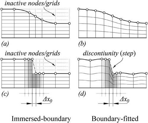
In Figure 1, the sudden pressure change due to inertia (∆pI) is modeled at point ②, where the film thickness abruptly changes, and the maximum pressure from RE (pRe(max)) occurs. 1D discretization is sufficient for the RE solution without inertia or with inertia using the BE method that depends only on um. As shown in Figures 1 and 3, 2D discretization is required for the NS method since the u and v velocity profiles need to be calculated. Film thickness (h) is only a function of x, so non-uniform grid can be preferred in the x-direction, and a uniform or non-uniform grid can be preferred in the y-direction. If the discretization is modeled as a boundary-fitted grid as in Figure 2b,d, grid transformation is required since RE is defined for Cartesian coordinates and the numerical calculation becomes a little more complex. In addition, the Cartesian immersed-boundary discretization in Figure 2a,c can also be used to simplify numerical calculations for especially rectangular domains such as RSB, thanks to the orthogonal grid. In the immersed-boundary discretization, continuous boundaries can be modeled stepwise as shown in Figure 2a, and discontinuous boundaries can be modeled as shown in Figure 2c. And, in this method, the grids outside the boundaries (inactive nodes) should also be treated as zero elements (0) in the matrix calculation. The same for computer graphics, NaN (“not a number”) values can be set instead of the zero-element used in the calculation. Since the method proposed in this study uses central FDM, two additional grids equal to ∆x0 are required to be added on either side of the virtual-grid (∆x0) where the discontinuity is modeled for the inertia implementation in order to accurately compute the partial derivatives in Equation (12) (see Figure 2c,d).
3.2 Computational Fluid Dynamics Analysis
To validate the present method, besides the referenced studies, 2D-full NSE were also solved for various bearing configurations using a finite volume method with the commercial CFD software package ANSYS Fluent. Due to the fact that the bearing geometries discussed in the current study are 2D and relatively simple, the use of a high number of grid elements in CFD was used to avoid grid independence problems in this study.
In CFD analysis, it is not easy to apply exactly the same boundary conditions as in analytical models. This makes it difficult to obtain fully developed flow conditions in these basic bearing geometries, which may lead to slightly inaccurate pressure results in the inlet zone. To minimize this problem and obtain zero atmospheric pressure at the inlet as in the analytical boundary conditions, velocity profiles close to the analytical velocity components (Equations 3 and 4 values at x = 0) were set as the velocity inlet. And zero atmospheric pressure was applied to the outlet. The upper surface was set as a stationary wall, while the lower surface was set as a moving wall with the value u0. The general settings and boundary conditions were set as in the studies used as validation references [5, 7]. Since thermodynamic effects were not considered in this study, constant viscosity was assumed, unlike in the reference studies. For the convergence criteria, the solver iteration was monitored until the residual values of all variables (continuity, x and y velocity) were less than 10−6. The physical parameters and lubricant properties for the current study are given in Table 1.
| Parameters | Rayleigh step bearing | Inclined bearing | |
|---|---|---|---|
| Inlet film thickness | h1 (mm) | 0.48 | 0.60, 0.48, 0.36 |
| Outlet film thickness | h2 (mm) | 0.240, 0.2572, 0.384 | 0.120 |
| Bearing length | L (mm) | 60, 80 | 80 |
| Step location | L1 (mm) | 22.6, 40.0, 57.4, 71.0 | — |
| Runner velocity | u0 (m/s) | 15, 25, 30 | 10, 25, 30, 40 |
| Lubricant properties | |||
|---|---|---|---|
| Viscosity | η (Pa s) | 0.03 | |
| Density | ρ (kg/m3) | 860 | |
4 Results and Discussion
In order to validate the numerical approaches proposed in this study and to evaluate the general applicability, several numerical solutions were performed on Rayleigh step and inclined bearing geometries with varying geometric parameters. The results were compared with both reference studies and ANSYS Fluent CFD solutions.
4.1 Inertial Effect in Rayleigh Step-Bearings
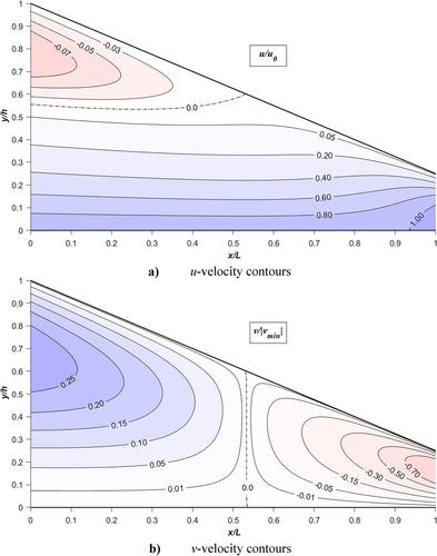
Figure 3 shows the ANSYS Fluent NSE solution of the u- and v-velocity contours together for a 1 mm length in the vicinity of the step for the reference problem [5]. As seen in the figure, the step wall results in a reverse flow and a sudden change in the u-velocity profile from convex to concave. And the v-velocity contours concentrate in a negative direction, especially at the lower end of the step, and disappear right after the discontinuity. The values of v-velocity contours were expressed in dimensionless form as v/|vmin|. Upon comparison, it appears that negative v-values are more dominant than positive values for the reference problem. The velocity contours for the u-component exhibit a negative distribution (reverse flow) in the upper pre-step zone, while they are uniformly distributed in the bottom zone, proportional to the runner speed. The combination of these velocity distributions on the right-hand side of Equation (2) results in pressure changes. It is therefore necessary to calculate these velocity distributions in order to be able to apply the effects of inertia effectively.
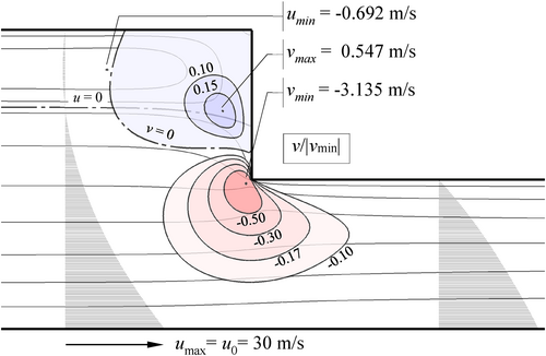
Alternatively, the velocity profiles generated by ANSYS Fluent can be simply approximated using Equations (3) and (4) from RE, assuming that the sudden velocity changes are concentrated only in a narrow zone, approximately 1% of the total bearing length (L), or in a length roughly equal to h1 for moderate runner speed. However, by utilizing Equations (3) and (4), the velocity distribution in the vicinity of the step can only be estimated within a pre-defined virtual-grid length (∆x0). Therefore, while this approach yields a pressure distribution quite similar to CFD results, ∆x0 should be sensibly defined, for example, in THD calculations or closely spaced grooved bearings. The contribution of these two velocity profiles causes a sudden pressure drop at the step zone (see Figure 4). Additionally, a pressure rise may also be seen since different contours will form at various h1/h2 ratios, particularly when h1/h2 > 4, [10].
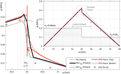
In Figure 4, the pressure drop phenomenon for the case from reference [5] was compared in order to examine the current discussed methods together. Additionally, streamlines obtained by CFD solutions were drawn by scaling 20:1 along the x-axis around the step region only. The pressure drop and the reverse flow pattern occur in a very narrow zone of approximately 1 mm for the current configuration and the streamlines for the remaining bearing zones are continuous. Therefore, the 1-mm-wide pressure distribution region around the step was drawn as a zoomed-in plot on the main graph. In the case, the value of ∆x0 was set to 10−4 in order to display grid points modeling the discontinuity. For each method except for the Reynolds theoretical solution with neglected inertia that is shown in dashed-dotted line, the pressure distributions throughout the bearing are almost identical except around the step. In the zoomed main graph, it can be seen that the pressure distributions of the CFD solution differ slightly on the top (stationary) and bottom (moving) walls, and that the Re + I solutions are converging to the pressure distribution pattern on the upper wall. While the Re + INS solution automatically approximates the CFD results, this approximation for the Re + IBe solution was achieved by determining the correction factor (α) to be 0.5 by trial and error. When comparing both solutions with the CFD results (white circles) from the reference study [5], it can be seen that the distribution after the step is slightly different. The fact that thermal effects were included in the reference study and the grid differences may be the reasons for this. As is noted in the literature, it is also seen here that Re + I methods can be easily utilized instead of challenging CFD methods. Moreover, it is seen that the Re + INS method presented here will produce more accurate results than the Re + IBe method, without the need for trial and error for the correction coefficient.
CFD solutions for various RSB scenarios with parameters of varying velocity (u0), bearing length ratio (β = L1/L), and film thickness ratio (λ = h1/h2) are provided in Ref. [7]. Some of the different scenarios in the mentioned study were randomly selected and compared collectively with the methods proposed in the current study in Figure 5. The correction factor (α) in Equation (10) was intentionally set to 1.0 in this figure to illustrate the distinction between the inertia calculation approaches of Re + INS and Re + IBe, and also to be equal to the method proposed in reference [4]. Here again, one can see that the Re + INS solutions are quite close to the reference results with a slight difference after the step because the reference work also includes thermal effects causing variable lubricant viscosity. Meanwhile, Vakilian, Nassab, and Kheirandish [7] also state that the lubricant inertia has a greater effect on lubricant pressure than temperature. Further, evaluating the Re + IBe results (dotted lines in Figure 5) reveals that the miscalculation rate varies across different configurations. Because in this approach, a specific correction factor (α) value needs to be determined for each configuration, as mentioned by Arghir, Alsayed, and Nicolas [4]. This means that the Re + IBe approach cannot be generalized. However, it has been observed that the correction factor (α) value, which is determined by trial and error to obtain results similar to CFD for the reference scenarios, may be specified between roughly 0.4 and 0.8 and is proportional to the bearing length ratio (β = L1/L).
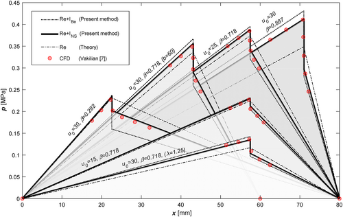
When the effects of fluid inertia are taken into account, it can be seen in Figure 5 that compared to the classical Reynolds theory, the inertia effect causes a slight increase in the pressure distribution before the step and a decrease in the distribution after the step, in accordance with the bearing length ratio (β = L1/L).
[Correction added on 10 March 2025, after first online publication: The equations “β = b1/b” has been changed to “β = L1/L” on this version.]
4.2 Inertial Effect in Inclined-Bearings
Positive and negative gradients in the v-velocity are generated for any disturbance (e.g., “step”) in the flow direction, as shown in Figure 3. This is also observed for any geometry with a converging gap, such as inclined bearings, where the velocity gradients calculated by Equations (3) and (4) are shown in Figure 6a,b. The u-velocity contours are seen in the upper part of the inlet with a negative distribution (reverse flow), while in the lower part of the outlet the runner velocity is slightly exceeded. And the v-values are very similar to the RSB case, with the negative values dominating over the positive ones. It can be said that this similar characteristic is the key reason why the RE velocity equations work reasonably well in the Re + INS approach for the discontinuous geometries previously mentioned. Because the discontinuity is modeled like a quasi-inclined bearing with an extremely short length (∆x0 → 0), and positive and negative velocity values are assigned to the nodes that need to be located, analogous to the distribution in the Full-NS solution.
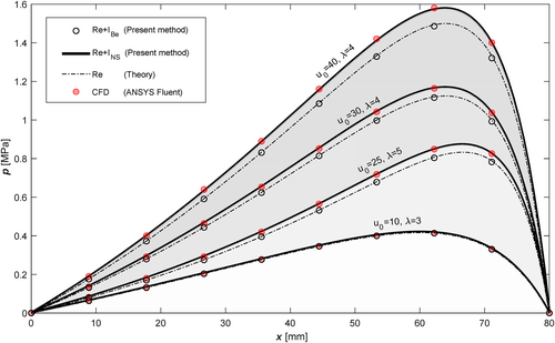
In the inclined bearings, compared to the classical RE solution where the inertia is neglected, the inertial contribution of these two velocity profiles leads to a slight increase in the pressure distribution along the bearing, as shown in Figure 7. In the figure, ANSYS Fluent CFD solutions were presented for various inclined bearing scenarios with parameters of different velocities (u0) and film thickness ratios (λ = h1/h2), and compared collectively with the approaches considered in the current study. Pay attention to the pressure rise, which becomes more noticeable, particularly for those with a film thickness ratio (λ = h1/h2) greater than 3. The Re + INS and CFD results seem to be quite consistent for this type of bearing as well. On the other hand, the Re + IBe approach appears to fail to reflect the inertial effects in this type of bearing, resulting in an almost equal distribution with the classical Reynolds theory, which neglects the inertia. Nevertheless, some manipulations can be attempted by selecting the correction factor (α) that is negative and large (e.g., between −10 and −20 for the scenarios considered) for an approximation (Figure 7).
5 Conclusions
The present article introduces a novel simplified numerical approach for accurately calculating the bearing pressure distribution in 1D-hydrodynamic lubrication problems by FDM, including film discontinuities causing the pressure drop (or rise) phenomena. For use in combination with RE, two potential approaches for estimating the pressure correction due to fluid inertia, namely, the Bernoulli effect and the averaged inertia, are discussed. The results obtained for various operating conditions are in agreement with the results of a commercial CFD software and data from the literature. Compared to CFD, which requires an intensive workload, the proposed method may provide extremely fast and highly accurate results for hydrodynamic problems. For the simple scenario given in Figure 4 with 20,000 elements in round numbers in the example close to the references [5, 7], using 10 parallel processors (Intel Core i7-9750H), for the continuity convergence criterion 10−6: The Fluent computation requires 30 s, while the proposed Re + I approach achieves the equivalent result in just 0.05 s by using sparse matrix operations in MATLAB. The significant difference in computation time is due to the fact that the proposed method can be easily modeled as matrix operations and does not require an iterative solution like conventional CFD.
- The NU-FDM formulation introduced here allows for a straightforward numerical modeling of film discontinuities with very few grids compared to CFD, and thus, by defining it as a system of equations, it can be easily solved by the direct matrix method with full accuracy instead of iterative solutions.
- Compared to the full Navier–Stokes (Fluent) results, the calculation with the combination of Reynolds and BEs (Re + IBe) fails to predict the pressure rise and overestimates the pressure drop due to the fluid inertia. This method can still be used if a specific correction factor (α) for each different problem can be estimated in advance.
- The method using the combination of the Reynolds equation and the Navier–Stokes inertia term (Re + INS) provides results very close to the full Navier–Stokes (Fluent) solutions and is capable of predicting both pressure rise and pressure drop caused by fluid inertia. It has been shown that the Re + INS approach can be used effectively to solve bearing problems without the need for complex CFD calculations.
- When the effects of fluid inertia are taken into account, compared with the classical Reynolds solution: In the RSB, it causes a slight increase in the pressure distribution before the step and a decrease in the distribution after the step, in accordance with the bearing length ratio (β = L1/L). In the inclined bearing, it causes an increase in the pressure distribution along the bearing length in accordance with the film thickness ratio (λ = h1/h2).
Conflicts of Interest
The authors declare no conflicts of interest.
Open Research
Data Availability Statement
The data that support the findings of this study are available from the corresponding author upon reasonable request.


