Model-Based Exploration of Web Guiding Behavior for a Novel Battery Cell Stacking Process
Abstract
Innovative production processes are required to meet the rapidly growing demand for batteries and the associated material trends. In particular, the process step of stack assembly using new machine concepts promises a high potential for optimization. However, these concepts are untested in practice. The use of digital models makes it possible to develop corresponding optimization approaches. This article presents the development of a model for the web guiding systems of electrodes and its integration into an overall machine model for a novel machine concept. Finally, optimization approaches are identified by determining appropriate controller parameters for the web guiding systems.
1 Introduction
The increasing global demand for battery cell capacity, for example, due to the transformation to electromobility, requires the deployment and application of efficient and high-throughput production machines.[1] Additionally, the observable market volatility necessitates a rapid adjustment of the production equipment. In particular, the process step of stack assembly is still limited in its throughput capacity due to discrete process control and is usually only able to produce one specific cell format.[2] It can therefore be deduced that the current problems need to be confronted with new machine technology. New machine concepts offer the potential to optimize battery production but have the disadvantage that they are often immature and unproven, resulting in high scrap rates of cost-intensive materials, especially during ramp-up.[3, 4] In battery production, the material has the highest impact on production costs. Reducing scrap rates is therefore of great importance.[5]
However, the use of digital machine and process models unlocks the potential for optimizing the development and application of new technologies. Approaches of modeling new technologies for stack assembly are presented in refs. [3, 6].
Against this background, the processing of continuous web materials is an essential part of the production process. The use of web guiding control and web tension control systems is therefore essential for precise processing.[7] In particular, corresponding inaccuracies in web processing are reflected in the quality of the battery cell stack.[8] The modeling of web tension disturbances in different roll-to-roll machines has already been part of various studies.[9] It is of high significance to include web edge control systems in the modeling of new machine technology for cell stack assembly as well. An approach of modeling web guiding systems is presented in ref. 10.
In summary, digital machine models for new stacking technologies offer a high potential for optimization. The core processes of these technologies are the processing of electrodes and separator webs. In addition to the web tension disturbances that occur, it is also necessary to model the web guiding systems in the context of the overall machine modeling. In this work, an existing machine model is extended by models of the web guiding systems. The considerations are made on a developed machine prototype for continuous and flexible cell stack assembly called Exinos.
2 Model Development and Integration
In the following, the machine technology considered in this work and the overall machine model are presented first. Based on this, the modeling principles of web guiding systems and their integration into the overall machine model are presented.
2.1 Introduction of the New Machine Technology and the Machine Model
The Exinos machine concept is shown in Figure 1.
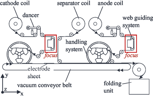
The input materials to the system are the cathode, anode, and separator that are fed into the system as a coil. For the anode and cathode, a format flexible singulation of the electrode sheets takes place. The function here is analogue and based on the Coil2Stack system presented in.[3] The electrode material is unwound and fed to the handling system via a roller system, a dancer, and the web guiding system. The web tension is controlled by the help of the dancer. The web edge is controlled in the z-direction by the web guiding system, which is the focus of this work. The web is rewound on the handling system. During winding, electrode sheets are separated from the web via a shear cut. The cathode sheets are placed on the vacuum conveyor belt and transported forward. Glue dots are then applied to the material surfaces so that the cathode sheets adhere to the separator web from the underside. The separated anode sheets are glued to the top side of the separator at a specific distance. This composite is then fed at a continuous speed to a folding unit, where the cell stack is assembled via a folding process. This allows continuous stacking, with the possibility of tool-less cell format changes using the handling systems.
Figure 2 shows the functionality of the overall machine model. This is a system simulation that was developed using the Simcenter Amesim software tool. The main components of the machine are described by the corresponding physical differential equations. For example, the rollers and the behavior of the drives are modeled. The crucial input and output parameters are shown in the figure. The principal input parameters are the machine setting parameters, such as the web speed, the web tension to be controlled, or the sheet length to be separated. The material is characterized by its Young's modulus and cross section, among other things. The main output parameter is the web tension at each position in the machine. However, all other values can be modeled, such as the web speeds. Detailed information on this can be found in ref. 3. A specific case of application for a model-based determination of the optimal control strategy for the web tension is presented in ref. 4.
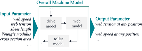
In the context of this work, a model of the web guiding systems is integrated into the described overall machine model using appropriate interfaces. In this context, an existing modeling approach for web guiding systems is used. This model is coupled to the overall machine model using the web tension and the web speed. Subsequently, a measured data set of the lateral displacement of the incoming web edge is used to simulate the lateral displacement of the outgoing web edge with the help of simulation studies. In these studies, controller parameters are varied and an appropriate optimum is derived. This integration and overall modeling approach is the main innovation of this work.
2.2 Basics for Modeling Web Guiding Systems
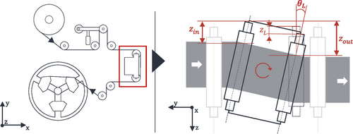
The basic relationships and key parameters for modeling web guiding systems are described below. For the purpose of this work, the relationships shown in ref. 9 are used. The offset pivot guides are installed in the machine. The corresponding boundary conditions are selected according to ref. 9. The functionality of the web guiding system is shown in Figure 3.
2.3 Integration into Overall Machine Model
The presented correlations are integrated into the existing model setup as part of the development of the overall machine model. Figure 4 illustrates the integration of the web guiding system model into the overall machine model.
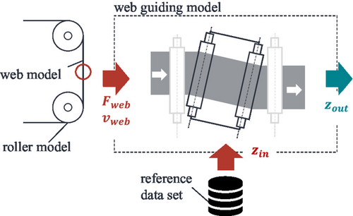
The main interface is provided by the parameters of the occurring web tension and the web speed at the position of the web guiding system. These parameters are taken from the corresponding web model shown in Figure 4. Furthermore, a time-dependent reference data set of the input web edge is transferred to the web guiding model. This can be a measured or generated data set. This procedure makes it possible to investigate the behavior of the web guiding system as a function of the setting parameters via the interface shown and the input web edge based on the model. In addition to the relationships shown, a modeled control loop for the web guiding system is added. Here, acts as the controlled variable, as the disturbance variable, and as the control variable.
3 Investigation of Web Guiding Behavior
After illustrating the development of the model, its applicability is presented in the following. First, the corresponding input data for , and are generated. Based on this, the output web edge is simulated with different control parameters.
3.1 Definition of the Input Parameter
The procedure for generating the input parameters is explained below. First, the parameters and are generated using the machine model presented. Table 1 shows the machine and material parameters considered.
| Machine parameter | Material parameter (anode) |
|---|---|
| Target web speed 12 mm s−1 | Young's modulus 40 GPa |
| Target web tension 12 N | Cross section 23.76 mm2 |
| Sheet length 210 mm | Grammage 0.16 mg mm−2 |
Figure 5 illustrates the modeled web tension and the modeled web speed at the position of the web guiding system. There are two web guiding systems in the machine concept. However, the functionality is the same. The explanations therefore refer to one web guiding system.
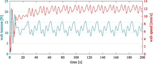
It is evident that both the web tension and the web speed are not constant during the operation of the system. This is mainly due to the contour of the grippers on the handling system, which is not circular but polygonal. This results in fluctuations during winding. In addition, increased fluctuations are recognizable during the start-up phase. This can be explained by the behavior of the overall system. The inertia of the deflection rollers in particular leads to fluctuations in web tension and speed during start-up.
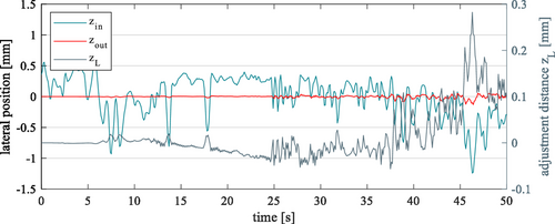
The reference data set for the lateral displacement of the incoming web is generated by means of a measurement. The web edge is detected by an infrared sensor in combination with the ekr CON 600 net ET (BST GmbH, Germany) controller. Figure 6 illustrates the measured data set. Significant fluctuations can be seen, mainly due to the nature of the wound electrode coil and a geometric inhomogeneity in the material. This web edge was not controlled, but only measured. The target value to be controlled is 0 mm. This reference data set is now being used to virtually explore and analyze different control strategies using the model of the web guiding system.

3.2 Application of Web Guiding Model
In the following, simulations of the web guiding system are carried out on the basis of the data shown for the web tension , the web speed , the reference data set of the input lateral web edge zin, and the material parameters shown in Table 1. In particular, the model-based exploration of different controller parameters is presented and discussed. 20 s of machine operation are used for the simulations. This means that the first 20 s of the modeled data sets for the web tension and web speed and the generated reference data set for the lateral displacement of the input web edge are considered. These 20 s are used to avoid an excessive increase in the computing time. However, it is generally also possible to consider higher times. The simulated data records for the web tension and the web speed show that a periodic process occurs which does not change any further. This will probably not significantly affect the result. Rather, the result will depend on the lateral displacement of the incoming web edge.
A proportional-integral-derivative (PID) controller is used for the simulation, whose gain factors , and are varied. and are varied from 0 to 1 in steps of 0.1, while is varied from 0 to 0.1 in steps of 0.01. These variation levels serve as an initial starting point and are intended to provide an overview of the effects of the control parameters. Table 2 provides an extract from the iterative variation of the controller gain factors.
| Setup nr. | PID control values | Sum of squares | ||
|---|---|---|---|---|
| 1 | 0 | 0 | 0 | 0 |
| 2 | 0.1 | 0 | 0 | 0.1 |
| 3 | 0.2 | 0 | 0 | 0.2 |
| … | 0.6 | 0.2 | 0.05 | 0.63 |
| 1331 | 1 | 1 | 0.1 | 1.42 |
The sum of squares factor of the gains is introduced for the subsequent visualizations of the results. Its calculation is shown in Table 2. The standard deviation of the modeled lateral displacement at the output of the web guiding system is used as a quality criterion. This characteristic value provides an indication of the degree of disturbance and the ability of the system to control the web edge.
A total of 1331 simulation runs were carried out using this iterative approach. Figure 7 illustrates the results of the simulation runs. The standard deviation of the simulated lateral displacement of the web edge is shown as a function of the controller gain factors in the form of a sum of squares. It is noticeable that a significantly high proportion of the factor combinations led to a high standard deviation (>10 mm). Only a small proportion of these possible combinations are suitable for controlling the web edge. In the selected scope, the parameter combination : 0.9, : 1, and : 0 was identified as optimal (point marked in red). The calculated standard deviation is 0.155 mm. Figure 8 also illustrates the results. However, a threshold of 1 mm has been chosen for the standard deviation for better visualization. The results may suggest that increasing the factor may result in a further reduction in the standard deviation.
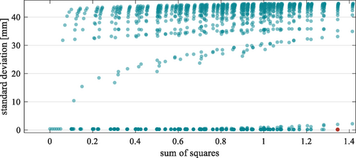
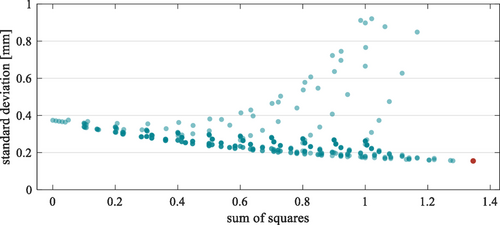
Figure 9 illustrates the initial measured values of zin, the simulated values of and the position values of the control variable . The previously determined optimum gains were used for the simulation of . In general, it can be seen that the error of has been reduced with the selected control parameters. However, the web edge is not controlled to 0 mm. It would be useful to perform further optimization loops at this point. The behavior of the control variable is also shown. This allows the dynamic behavior of the web guiding system to be characterized. Knowledge of the material characteristics can be used to estimate whether or not the material is damaged by the behavior of the web guiding system.
4 Conclusion
This work has highlighted the need to model novel machine systems for battery cell stacking. In particular, the quality of the electrode web guiding process of electrodes influences the subsequent quality of the cell stack. In the context of developing an overall machine model, this article describes the modeling of the web guiding systems and their integration into the overall machine model. Using simulated input variables of the web tension and web speed and a measured web edge, an exemplary production scenario was presented, based on which the controller parameters of the web guiding system were optimized. A value of 0.9, a value of 1, and a value of 0 were found to be the optimum combination for the scenario described. The main purpose of the presented model is to help optimize the start-up process in a changing production scenario with the intention of reducing scrap rates.
Acknowledgements
The authors would like to express their appreciation to all industry partners, research partners, and the German Federal Ministry for Economic Affairs and Climate Action for supporting the ProMoBatt project (funding code: 16BZF357F). This work contributes to the research performed at KIT Battery Technology Center (KIT-BATEC) and at Center for Electrochemical Energy Storage Ulm Karlsruhe (CELEST).
Open Access funding enabled and organized by Projekt DEAL.
Conflict of Interest
The authors declare no conflict of interest.
Open Research
Data Availability Statement
The data that support the findings of this study are available from the corresponding author upon reasonable request.


