Refrigerant Selection for Heat Pumps: The Compressor Makes the Difference
Abstract
Increasingly stringent regulations and new applications require selecting improved refrigerants for heat pumps. The selected refrigerants should be environmentally friendly and maximize the performance of the heat pump process. Systematic refrigerant selection methods usually model the compressor with one fixed isentropic efficiency identical for all refrigerants. However, compressor studies indicate that the isentropic efficiency may be highly refrigerant-dependent. Herein, the need for a refrigerant-dependent compressor model for refrigerant selection is investigated. For this purpose, a refrigerant-dependent compressor model is combined with an integrated design of refrigerant and heat pump process. To guarantee a comparable nominal heating power among refrigerants, the compressor design is tailored to the refrigerant by expanding the refrigerant-dependent compressor model toward compressor sizing. Integrating compressor design into systematic refrigerant selection is enabled by a computationally efficient model implementation. Accounting for refrigerant-dependent compression substantially changes the resulting refrigerant ranking compared to the widely used assumption of identical isentropic efficiencies for all refrigerants: The best-performing refrigerant is not even identified among the best ten refrigerants when assuming identical isentropic efficiencies. Consequently, compression is identified as the main driver for differences in refrigerant performance. Therefore, integrating refrigerant-dependent compressor models is crucial for systematic refrigerant selection.
1 Introduction
Electrification is a promising option for decarbonizing heat supply[ 1 ]: Residential heating and domestic hot water will be mostly supplied by vapor-compression heat pumps in the future.[ 2 ] From 2015 to 2020, the global heat pump stock has already increased by 10% per annum.[ 3 ] The International Energy Agency claims that the global heat pump stock should further increase from 180 million devices in 2020 to 600 million devices by 2030 to meet the Net Zero Emissions by 2050 scenario.[ 3 ] In addition to the more established residential heat pumps, electrically driven heat pumps have also been identified as the key technology for industrial heat generation.[ 4 ] The growing role of heat pumps for climate change mitigation is hampered by the high global warming potential of state-of-the-art refrigerants. Many countries have already started partly implementing exit scenarios from hydrofluorocarbons, such as the F-gas regulation in the European Union.[ 5 ] International agreements like the Kigali Amendment to the Montreal Protocol[ 6 ] even require the complete exit from refrigerants with high global warming impact. Therefore, major activities are underway to select novel refrigerants. Recently, various alternatives such as hydrofluoroolefins or natural refrigerants are discussed. However, these refrigerants are known to suffer from various drawbacks.[ 7 ] Thus, the challenge remains in finding the most suitable and efficient refrigerant for specific applications.[ 7, 8 ]
For this purpose, systematic refrigerant selection approaches have been proposed which can generally be divided into screening and design approaches: Screening approaches filter existing fluid databases based on certain target fluid properties or the refrigerant's predicted process performance obtained from process simulations or optimizations.[ 7-9 ]
In contrast, design approaches use computer-aided molecular design (CAMD) techniques to construct refrigerant molecules from molecular building blocks in silico.[ 10 ] These molecular building blocks, so-called functional groups, are assembled to a molecular structure. The feasibility of this molecular structure is ensured by structural CAMD constraints. In contrast to the screening approaches, the design approaches are not limited to the predefined fluid database and thus cover a broader molecular space.[ 10 ] Therefore, the design approaches may also enable the design of molecules not contained in the fluid databases used for the screening approach.
The molecular design objective is based on either simplified indicators such as refrigerant target properties[ 11, 12 ] or process-based objectives by integrating refrigerant and process design in one optimization problem.[ 13-15 ] This integrated computer-aided molecular and process design (CAMPD) is beneficial compared to the molecular design based on simplified indicators as it captures trade-offs between refrigerant and heat pump process and thus tailors the refrigerant to the application.[ 16 ]
Evaluating refrigerant candidates with regard to their economic or thermodynamic performance requires a process model of the heat pump. Within the process model, an increasing degree of detail improves the prediction quality[ 17 ] but also the computational effort for the evaluation. However, the goal of refrigerant selection is not to predict the heat pump performance quantitatively but to accurately identify the optimal refrigerants. For this purpose, the process model must capture all interactions between the refrigerant and the heat pump that substantially influence system performance. At the same time, the process models must retain computational tractability.
The interactions between refrigerant and heat pump result mainly from the refrigerant-dependent performance of the heat pump equipment. Particularly, the compressor's isentropic efficiency has a strong influence on the coefficient of performance (COP) due to the substantial exergy loss during compression.[ 18 ] Still, studies on systematic refrigerant selection frequently assume that identical isentropic efficiencies can be achieved for all refrigerants if the compressor design is tailored to the refrigerant. As a consequence, the studies either neglect compressor losses[ 7, 19-21 ] or model the compressor with an isentropic efficiency identical for all refrigerants.[ 9, 22-24 ] Other studies introduce process and refrigerant dependency using empirical correlations for the isentropic efficiency.[ 7, 20, 25 ] However, these empirical correlations are fit to data for only a few refrigerants, and refrigerant extrapolation is neither guaranteed nor proven.
Nevertheless, literature indicates that the isentropic efficiency indeed strongly depends on refrigerant properties: Some of the present authors and coworkers analyzed if these refrigerant-induced differences in isentropic efficiency can be overcome by tailoring the compressor design to the refrigerant.[ 26 ] For reciprocating-piston compressors, the authors simulate tailoring the compressor design to the refrigerant by scaling the compressor geometry and by reducing prevalent losses for each refrigerant. The isentropic efficiency is shown to depend strongly on the refrigerant even after tailoring the compressor design to the refrigerant. Thus, achieving identical isentropic efficiencies for all refrigerants appears impossible in practice.
To capture the refrigerant dependency, (semi-)physical compressor models based on physical relations have been developed.[ 27-30 ] However, most models are parametrized for a specific refrigerant such that their potential for refrigerant extrapolation is unclear.[ 27-29 ] In contrast, Roskosch et al.[ 30 ] developed a reciprocating-piston compressor model particularly suitable for refrigerant extrapolation. The compressor model exhibits lean parametrization and does not rely on extensive compressor performance data. So far, the model has been used for pure refrigerants[ 30, 31 ] and for refrigerant mixtures.[ 26 ] However, as a (semi-)physical compressor model, it solves mass and energy balances and is therefore computationally expensive.
To conclude, current refrigerant selection methods often model the compressor as refrigerant-independent, assuming one fixed isentropic efficiency identical for all refrigerants. While this assumption does not seem to hold in practice,[ 26 ] it is yet unclear how the assumption influences the results of refrigerant selection. To date, to the best of our knowledge, no studies exist that systematically assess the influence of the compressor model on systematic refrigerant selection.
In this work, we investigate the need for a refrigerant-dependent compressor model for refrigerant selection. For this purpose, we integrate a refrigerant-dependent compressor model into refrigerant design: an integrated design method of molecules and processes[ 13 ] is combined with a reciprocating-piston compressor model where isentropic efficiencies depend on refrigerant and operating point. Tailoring the compressor design to the refrigerant is enabled by expanding an existing refrigerant-dependent compressor model[ 30 ] by a novel approach for compressor design. We study the influence of the compressor model on the results of systematic refrigerant selection by comparing the resulting refrigerant ranking to using identical isentropic efficiencies for all refrigerants.
The paper is structured as follows: In Section 2, we present the models for heat pump process and compressor and the systematic refrigerant selection method. The compressor model's influence on refrigerant selection is assessed and discussed in Section 3. In Section 4, conclusions are drawn.
2 Integrated Design of Refrigerant and Heat Pump Process with Refrigerant-Dependent Compressor Design Model
As an exemplary refrigerant selection method, we use the 1-stage Continuous-Molecular Targeting Computer-Aided Molecular Design (1-stage CoMT-CAMD) method[ 13 ] for the integrated design of refrigerant, compressor, and heat pump process. However, the main findings of this study do not depend on the refrigerant selection method employed. Section 2.1 elaborates on the process model, Section 2.2 presents the compressor design model, while Section 2.3 introduces the 1-stage CoMT-CAMD method, the thermodynamic model, and the resulting optimization problem.
2.1 Process Model
We study the integrated design of refrigerant and heat pump process for a low-temperature residential air–water heat pump with a nominal heating power of (Table 1 ).
| Process parameter | Variable | Value |
|---|---|---|
| Target heating power | 6 kW | |
| Sink temperature at inlet | 25 °C | |
| Sink temperature at outlet | 35 °C | |
| Source temperature (isothermal) | 5 °C | |
| Superheating | 5 K | |
| Minimum approach temperature | 1 K | |
| Minimum pressure | 1 bar | |
| Maximum reduced pressure | 0.8 |
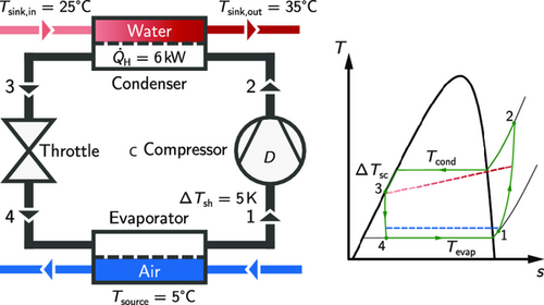
Within the condenser, the refrigerant is used to heat water from by . Thereby, the refrigerant is fully condensed and then subcooled to . Finally, the subcooled liquid is throttled to the desired evaporator pressure. The evaporator pressure is calculated as the saturation pressure at evaporation temperature . The throttle is described by an isenthalpic state change. All process parameters are included in Table 1. A detailed description of the thermodynamic process model and all assumptions is provided in the Section S1, Supporting Information.
The degrees of freedom of the heat pump process model are: the evaporation temperature , the condensation temperature , and the subcooling . A fixed heating power of can be obtained for all refrigerants by varying the theoretical mass flow rate , which depends on the compressor geometry.
2.2 Compressor Design Model
The refrigerant-dependent compressor model used in this study is a (semi-)physical model for a reciprocating-piston compressor developed specifically to allow refrigerant extrapolation.[ 30 ] The compressor model discretizes the compression cycle and solves time-dependent mass and energy balances to calculate the isentropic efficiency (Equation 1) and the volumetric efficiency (Equation 2) for a given inlet state and outlet pressure . The model considers losses due to friction, flows at the valves, and heat transfer. These losses are described by physical relations that build on the description of a reference compressor (index ‘ref’) for which the following parameters have been fitted: the friction pressure , the effective flow areas of the suction and the discharge valves and , and the relative clearance volume . The model is validated on 63 experimental data points of various pure and mixed refrigerants and operating points.[ 30 ] Thus, the presented framework could be employed to study the design of zeotropic refrigerants. In the original study, relative mean errors of below 4.4% are achieved for compressor and refrigerant extrapolation.[ 30 ]
In this work, the compressor design is tailored to the refrigerant by expanding the compressor model[ 30 ] toward compressor sizing. More specifically, the compressor design model allows to change the compressor diameter by rescaling the diameter of the reference compressor to a new diameter (index 'scale’).
The resulting input variables of the compressor design model are still the inlet state with temperature and pressure , the outlet pressure , but now also the compressor diameter D. Thus, the compressor diameter D is now an equipment degree of freedom. When combining process and compressor design model, the compressor diameter D determines the theoretical mass flow rate as a process degree of freedom. All fixed compressor parameters are summarized in Table 2 .
| Compressor parameter | Variable | Value |
|---|---|---|
| Diameter (reference compressor) | 34 mm | |
| Diameter-to-stroke ratio | 1.25 | |
| Rod/crank | 3.5 | |
| Relative clearance volume (reference compressor) | 0.1 | |
| Number of pistons | 2 | |
| Friction pressure (reference compressor) | 80.12 kPa |
The presented refrigerant-dependent compressor design model is used for a refrigerant design: To identify the thermodynamically best combination of process, compressor, and refrigerant, the process, equipment, and molecular degrees of freedom are optimized simultaneously using the 1-stage CoMT-CAMD method introduced next.
2.3 1-stage CoMT-CAMD Method
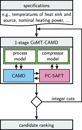
The compressor model is described only by equality constraints depending on the process and the equipment degrees of freedom x and the thermodynamic equilibrium properties θ (cf., Section 2.2).
The thermodynamic equilibrium properties θ are calculated from the thermodynamic property model h. For this purpose, we employ here the PC-SAFT equation of state. The PC-SAFT parameters are determined from the molecular structure described by functional groups using the homosegmented group contribution approach.[ 35 ]
The structural feasibility of the designed molecules is ensured by the equality and inequality constraints of the CAMD formulation and ,[ 36 ] e.g., the octet rule. Computing caloric properties requires an expression for the ideal gas heat capacity . Here, the ideal gas heat capacity is calculated using the group contribution method developed by Joback and Reid.[ 37 ]
In this work, the molecular design space consists of all structurally feasible molecules that can be assembled with the functional groups parametrized by Sauer et al.[ 35 ] Thus, potential refrigerants can be alkanes, alkenes, aromatics, cyclohexanes, cyclopentanes, alkynes, as well as further polar and associating molecules.
Some molecules, such as small or halogenated molecules, are not covered by the group contribution method.[ 35, 38 ] We add these molecules to our optimization problem using substance-specific parameters for both PC-SAFT and the heat capacity model of Joback and Reid. PC-SAFT parameters for halogenated molecules are taken from Wang et al.,[ 19 ] while ideal gas heat capacity parameters are adjusted to data from the NIST REFPROP database.[ 39 ] We include all halogenated refrigerants from the final selection by McLinden et al.[ 7 ] for which both PC-SAFT parameters and REFPROP data are available (15 of 23 refrigerants). An overview of the included functional groups and additional molecules with their parameters is provided in the Section S4 and S5, Supporting Information.
We implement the process model in Python. Since our compressor model is computationally expensive, we implement it in the computationally efficient programming language Rust with an interface to Python. This computationally efficient implementation reduces the evaluation time of the compressor model from around 60 s to the range of milliseconds. Hereby, we enable using the compressor model within systematic refrigerant selection where numerous model evaluations are necessary. Thermodynamic properties of the refrigerant are calculated using the PC-SAFT implementation provided in the framework.[ 40 ]
The resulting MINLP (Equation 9) is solved using the Branch and Bound algorithm of the optimizer Knitro.[ 41 ] The optimization problem comprises 56 variables: 7 binary variables, 44 integer variables, and 5 continuous variables. The Branch and Bound algorithm aims to find the optimal solution that fulfills the integer constraints, i.e., here, the integer number of functional groups. For this purpose, the algorithm solves continuous nonlinear subproblems, so-called relaxations, until an integer feasible solution is found that fulfills optimality criteria. Due to the nonconvexity of the problem, Knitro does not ensure global convergence. To capture possible local maxima, we generate a ranking of candidate refrigerants using integer-cut constraints (cf., Figure 2). For this purpose, the optimization is carried out repeatedly: For each optimization, all previously found refrigerants are excluded from the molecular design space by adding integer-cut constraints.[ 13 ]
3 Results and Discussion
In the following, we present the top refrigerants identified by the integrated design (Section 3.1) and analyze the observed differences in refrigerant performance (Section 3.2). After investigating how the compressor's refrigerant dependency influences an exemplary heuristic refrigerant selection criterion (Section 3.3), we discuss how our main findings can be transferred to other case studies (Section 3.4).
3.1 Refrigerant Rankings
The top 10 refrigerants identified by the integrated design with the refrigerant-dependent compressor model consist mainly of halogenated hydrocarbons, alkenes, and alkanes (Table 3 ).
| Refrigerant-dependent compressor model | |||
|---|---|---|---|
| Rank | Refrigerant | COP | |
| 1 | R-32 | 5.11 | 0.0% |
| 2 | R-161 | 5.10 | 0.3% |
| 3 | Cyclopropane | 5.05 | 1.2% |
| 4 | Propene | 5.02 | 1.9% |
| 5 | Dimethyl ether | 5.01 | 2.0% |
| 6 | R-152a | 4.98 | 2.6% |
| 7 | Propane | 4.96 | 3.1% |
| 8 | R-22 | 4.78 | 6.6% |
| 9 | R-134a | 4.75 | 7.1% |
| 10 | Methylamine | 4.72 | 7.8% |
However, one ether and one amine are also among the top 10 refrigerants: dimethyl ether and methylamine. Overall, the best-performing refrigerants are R-32 (difluoroethane) with a COP of 5.11 and R-161 (fluoroethane) with a COP of 5.10. Both R-32 and R-161 are already discussed as potential refrigerants in the literature[ 7, 42 ] and already deployed in heat pump systems. The COP of the 10th best refrigerant, methylamine, is 7.8% lower than the maximum COP of R-32.
Additionally, the integrated design is performed with a refrigerant-independent isentropic efficiency of 60% for all refrigerants (Table 4 ). The top 10 refrigerants consist mainly of halogenated hydrocarbons, alkenes, and alkanes with methylamine as the best-performing refrigerant. All noncyclic alkanes and alkenes among the top 10 refrigerants have four heavy atoms, e.g., carbon atoms. However, the range of those refrigerants’ COPs is comparably small: with 5.11, the COP of the 10th best refrigerant, R-161, is only 3.0% lower than the COP of methylamine with 5.27.
| identical for all refrigerants (60%) | |||
|---|---|---|---|
| Rank | Refrigerant | COP | |
| 1 | Methylamine | 5.27 | 0.0% |
| 2 | 1-Butene | 5.21 | 1.1% |
| 3 | Isobutylene | 5.21 | 1.1% |
| 4 | Dimethyl ether | 5.20 | 1.3% |
| 5 | Butane | 5.19 | 1.5% |
| 6 | Cyclopropane | 5.18 | 1.7% |
| 7 | Isobutane | 5.16 | 2.1% |
| 8 | R-152a | 5.16 | 2.1% |
| 9 | R-1243zf | 5.12 | 2.8% |
| 10 | R-161 | 5.11 | 3.0% |
The COPs achieved with the refrigerant-dependent compressor model are lower than with identical isentropic efficiencies. This difference in COP generally results from the lower isentropic efficiencies obtained by the refrigerant-dependent compressor model compared to the refrigerant-independent isentropic efficiency of 60% (Figure 3 ). For R-32 and R-161, as the two refrigerants with a refrigerant-dependent isentropic efficiency of about 60% and greater, respectively, the COPs with the refrigerant-dependent compressor model are similar and greater than with identical isentropic efficiencies.
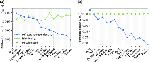
The design with identical isentropic efficiencies does not find the best refrigerants (Table 3 and 4): R-134a (1,1,1,2-tetrafluoroethane), propene, R-22 (chlorodifluoromethane), propane, and R-32 are not among the top 10 refrigerants for the identical isentropic efficiency although they are identified among the top 10 when accounting for the compressor's refrigerant dependency. In particular, R-32 is the overall best-performing refrigerant using the refrigerant-dependent compressor model. In contrast, the design with identical isentropic efficiencies identifies 1-butene, isobutylene, butane, isobutane, and R1243zf (3,3,3-trifluoroprop-1-ene) among the top 10 refrigerants. These refrigerants are not identified in the top 10 with refrigerant-dependent compressor models and are thus not expected to perform well for real heat pump applications where refrigerant properties are known to affect compression.
In addition to the changes in the top 10 refrigerants, the order of the best refrigerants changes if refrigerant-dependent compression is neglected (Figure 3): even the refrigerants identified by both designs appear in a different order. This change in order is confirmed by the Pearson correlation coefficient r. To calculate the Pearson correlation coefficient, the COPs are recalculated for all refrigerants that are not part of the top 10 for the refrigerant-dependent compressor model using identical isentropic efficiencies, and vice versa. Then, the refrigerants are sorted according to their COP (Figure 3). With a Pearson correlation coefficient of , the two orders of the refrigerants are slightly negatively correlated, i.e., the better-performing refrigerants for one compressor model have a tendency to perform worse for the other compressor model.
In conclusion, the identified refrigerants differ among the top 10 refrigerants: the order of the top 10 refrigerants nearly reverses and the best-performing refrigerant is not even identified when assuming identical isentropic efficiencies. Moreover, only the refrigerant-dependent compressor model can resolve all significant differences between refrigerants, as the COPs of the top 10 refrigerants are in a smaller range for the identical isentropic efficiencies than for the refrigerant-dependent compressor model.
3.2 Observed Differences between Refrigerants
To understand the trade-offs between refrigerants, compressor, and heat pump process, we analyze the relative COP differences between refrigerants in detail. Due to the specification of the case study, the optimal condensation temperature , evaporation temperature , and subcooling are similar for all refrigerants and both compressor models. Thus, the optimal condensation temperature is between 33 and 35 °C, the optimal evaporation temperature is 0 °C, and the optimal subcooling is between 8 and 9 K: The optimizer selects the temperatures to minimize the exergy losses within the heat exchangers, while fulfilling the minimum approach temperature of wherever possible.
The isentropic compression work is a function of the refrigerant properties at the given operating conditions, e.g., the isobaric heat capacity , and the compression ratio Π. Similarly, a major share of the specific condensation heat usually depends on the enthalpy of vaporization . Thus, a high enthalpy of vaporization , a low isentropic compression work , and a high isentropic efficiency are beneficial with regard to the COP. As a result, COP differences between refrigerants stem from differences in these refrigerant properties–and from potential differences in the isentropic efficiency .
Consequently, all performance differences between refrigerants are due to the refrigerant properties and their interaction if the refrigerant dependency of the compression is neglected. These differences between refrigerants have a small impact on the COP compared to the isentropic efficiency, causing the COPs with identical isentropic efficiencies to be in a narrow range compared to the COPs with the refrigerant-dependent isentropic efficiency.
In contrast, compression is identified as the main driver for differences in refrigerant performance if refrigerant dependency is considered: Here, the comparably large COP differences between refrigerants are due to differences in the refrigerant-dependent isentropic efficiency (cf., Equation 10). To gain further insights into the refrigerant-dependent isentropic efficiency, Figure 4 shows the isentropic efficiency , the density at the compressor inlet , and the optimal compressor diameter D for each of the combined 15 refrigerants from both top 10 rankings. In agreement with the literature,[ 26 ] refrigerants with smaller compressor diameter (smaller displacements) have a tendency for greater isentropic efficiencies . For example, R-32 as a refrigerant with an outstandingly high density at the compressor inlet requires the smallest compressor diameter D and also achieves the greatest isentropic efficiency . In contrast, the lowest isentropic efficiencies are observed for the alkanes and alkenes that are low-density refrigerants with large compressor diameters D. Roskosch et al.[ 26 ] explain this observation by the reduction in friction losses due to the smaller piston. This reduction in friction losses benefits the isentropic efficiency .
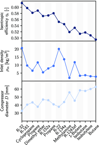
Overall, compression is the main driver for differences in refrigerant performance if refrigerant dependency is accounted for. High densities at the compressor inlet result in small compressor diameters. Small compressor diameters lead to small constant losses benefitting the refrigerant performance within the compressor and thus also the overall refrigerant performance.
3.3 Comparison with a Heuristic Refrigerant Selection Criterion
Heuristic screening approaches often consider target refrigerant properties such as critical temperature, critical pressure, heat capacity, or enthalpy of vaporization as simplified process indicators. Those simplified process indicators aim to mirror trends between refrigerants, but neither contain information on the application nor on the process.
The obtained results are used to illustrate the performance of an exemplary heuristic screening criterion in the face of refrigerant-dependent compression. Figure 5 compares the COPs and the critical temperature for the combined 15 refrigerants from both top 10 rankings (Figure 3). For identical isentropic efficiencies, the refrigerants with greater critical temperature tend to exhibit greater COPs. This observation is in line with the heuristic screening criterion for refrigerant selection favoring refrigerants with greater critical temperatures .[ 43-45 ] In contrast, no clear correlation is observed between the critical temperature and the COP if the refrigerant-dependent compressor model is used. For the given case study, the best-performing refrigerants even have comparably low critical temperatures .
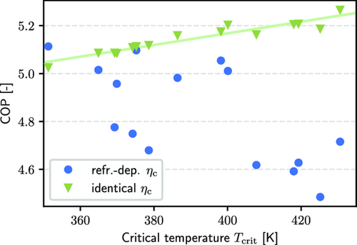
When assuming identical isentropic efficiencies for all refrigerants, heuristic screening criteria based on critical conditions (here: critical temperature) closely mirror trends between refrigerants. In contrast, if refrigerant dependency is considered, these heuristic screening criteria fail. Therefore, considering the heat pump process for systematic refrigerant selection instead of simplified process indicators appears even more important in the face of the compressor's refrigerant dependency.
3.4 Transferability of Findings
For the given case study, the design with identical, refrigerant-independent isentropic efficiencies neglects substantial trade-offs between refrigerants. Thus, refrigerants selected with such a simplified compressor model will likely be suboptimal if deployed in a real-world system with an actual compressor.
These findings are not automatically transferable to other compressor types because the findings have been derived using a model for a reciprocating-piston compressor.[ 30 ] In particular, residential heat pumps are often equipped with scroll, screw, or rotating piston compressors besides reciprocating-piston compressors.[ 46 ] All these compressor types are positive displacement compressors based on the same physical principle and are affected by similar losses: friction, flow, and electrical losses. In practice, these positive displacement compressors also show similar trends in isentropic and volumetric efficiency.[ 46 ] Furthermore, Roskosch et al.[ 30 ] identified the ratio of isentropic compressor power (refrigerant-dependent) and refrigerant-independent compressor losses (e.g., friction losses) as the main drivers for the refrigerant dependency of compressor efficiencies. We expect these effects to occur with all positive displacement compressors, making our results qualitatively transferable to heat pumps equipped with other types of positive displacement compressors.
In contrast, transferring the findings to other applications, i.e., other heat pump configurations, or other temperature levels, seems reasonable: The compression always substantially influences the COP due to the compression's high exergy losses compared to the exergy losses within heat exchangers.[ 18 ] Moreover, the application studied in this work has a comparably small molecular design space of feasible molecules due to the low temperatures. Even for this small molecular design space, the top refrigerants and their rankings differ. With an increasing size of the molecular design space, e.g., for high-temperature applications or if more functional groups are considered, the top refrigerants and the rankings are expected to differ even more.
The same is expected for mixtures: Roskosch et al.[ 47 ] show that the isentropic efficiencies of the mixture components and the resulting isentropic efficiency of the mixture are key to realizing the benefits of the temperature glide. Due to the higher combinatorial complexity and the increased flexibility of mixtures due to their composition, we also anticipate more substantial differences in refrigerant ranking if refrigerant-dependent compression is considered.
Finally, the findings of this study do not depend on the used systematic refrigerant selection method. The same results could have been obtained by screening a refrigerant database based on process simulations or optimizations with a refrigerant-dependent compressor model. Thus, all findings of this work also apply to process-based screening approaches.
4 Conclusions
This work studies the effect of the compressor model's refrigerant dependency on systematic refrigerant selection. For this purpose, an integrated design method of molecules and processes[ 13 ] is combined with a reciprocating compressor model Roskosch et al.[ 30 ] including a novel approach for compressor design to account for refrigerant- and operating-point-dependent isentropic and volumetric efficiencies. The refrigerants identified using the refrigerant-dependent compressor model are compared to results of a design with the widely used assumption of identical isentropic efficiencies for all refrigerants.
The analysis shows that switching from identical to refrigerant-dependent isentropic efficiencies changes the observed trade-offs between the refrigerants and the heat pump process, not only quantitatively but also qualitatively. As a result, the obtained refrigerant ranking changes. Consequently, refrigerant-dependent compressor modeling is crucial in systematic refrigerant selection to identify an optimal combination of refrigerants and heat pump processes. Moreover, this work demonstrates that integrating refrigerant-dependent compressor models into systematic refrigerant selection is possible by using computationally efficient model implementations.
Acknowledgements
This work was funded by BRIDGE as part of the project “High Efficiency High-Temperature Heat Pumps with Temperature Glide” (grant no.: 203645) by the Schweizerischer Nationalfonds zur Förderung der Wissenschaftlichen Forschung (SNF).
Open access funding provided by Eidgenössische Technische Hochschule Zürich.
Conflict of Interest
The authors declare no conflict of interest.
Open Research
Data Availability Statement
The data that support the findings of this study are openly available in Paper The Compressor Makes the Difference at https://gitlab.ethz.ch/epse/molecular-design-public/paper-the-compressor-makes-the-difference, reference number 37297.


