Crystal structure of HLA-A*2402 complexed with a telomerase peptide
Abstract
HLA-A*2402 is the most commonly expressed HLA allele in oriental populations. It is also widely expressed in the Caucasian population, making it one of, if not the most abundant HLA I types. In order to study its structure in terms of overall fold and peptide presentation, a soluble form of this HLA I (α1, α2, α3 and β2m domains) has been expressed, refolded and crystallized in complex with a cancer-related telomerase peptide (VYGFVRACL), and its structure has been solved to 2.8 Å resolution. The overall structure of HLA-A*2402 is virtually identical to other reported peptide-HLA I structures. However, there are distinct features observable from this structure at the HLA I peptide binding pockets. The size and depth of pocket B makes it highly suitable for binding to large aromatic side chains, which explains the high prevalence of tyrosine at peptide position 2. Also, for HLA binding at peptide position 5, there is an additional anchor point, which allows the proximal amino acids to protrude out, providing a prominent feature for TCR interaction. Finally, pocket F allows the anchor residue at position 9 to be bound unusually deeply within the HLA structure.
Abbreviations:
-
- A24:
-
HLA-A*2402
-
- A24 VYG:
-
A24 complexed to VYG
-
- AU:
-
asymmetric unit
-
- CS:
-
Crystal Screen
-
- P:
-
peptide residue position
-
- PC:
-
C-terminal peptide position
-
- pHLA I:
-
peptide-HLA I
-
- RMSD:
-
root mean square deviation
-
- VYG:
-
VYGFVRACL
Introduction
The CTL response to particular antigens can be highly variable depending on the HLA class I (HLA I) type expressed by the individual 1. This is due to the compatibility of the binding pockets in the HLA α1:α2 binding groove to anchor residues that stabilize the peptide at specific sites 2, 3. Peptide residue positions P2 and PC (C-terminal residue) have been shown to be important for binding to most HLA I types 4. This restricts the peptide range available for particular HLA types, often leading to a highly variable response to the same disease. This observation has been described in relation to a number of diseases (e.g. severe malaria 5, rheumatoid arthritis 6, insulin-dependent diabetes mellitus 7 and many others 8), where individual expression of different HLA alleles can lead to susceptibility or resistance, depending on the condition. Probably through natural selection, certain HLA I types have become more dominant in the human population, depending on the immune response they elicit.
A possible example of this phenomenon is HLA-A*2402 (A24), a highly prevalent HLA I allele, particularly in people of Asian origin 9; reportedly, A24 is expressed in 20% of Chinese 10, in 70% of Japanese and in 35% of Indian populations 11. A24 is also highly expressed in Caucasian populations, being present in around 19% of individuals 11, and is expressed in around 60% of Australasian Aboriginals 10. Accordingly, A24 is involved in the presentation of important antigens to CTL in a number of important diseases 12–15.
Telomerase is an enzyme involved in DNA replication, cell cycle, apoptosis, and particularly in the maintenance of telomeres at the ends of chromosomes 16. In humans, somatic expression of telomerase is associated with cellular immortality and often with progression to a malignant state 17–19. Thus, peptides derived from telomerase have been shown to be some of the most universal antigen markers for human cancers.
We have cloned, expressed, refolded and purified a soluble fragment of A24 containing the α1, α2 and α3 domains, as well as β2 m, in complex with the antigenic telomerase peptide VYGFVRACL (VYG). In order to investigate the telomerase peptide presentation by A24, crystals have been grown using a hanging drop method and their structure has been solved to 2.8Å resolution.
Results
Overall structure of A24 complexed to VYG (A24 VYG)
The structure of A24 complexed to VYG (A24 VYG) was solved at 2.8 Å and refined to an Rcryst and Rfree of 18.3% and 25.6%, respectively (Table 1, 2). The complex crystallized in space group C2 with unit cell parameters a = 125.65 Å, b = 132.04 Å, c = 91.45 Å and β = 128.9º. The overall model consists of two molecules of A24 VYG in the asymmetric unit (AU). The A24 VYG molecules form a dimer linked by a sulfate-mediated salt-bridge. A pseudo twofold axis, centered on the sulfur atom, is formed between residues R79 and R83 of one A24 VYG molecule and their equivalents of the other copy in the AU (Fig. 1). Extensive non-specific crystal contacts are also made, stabilizing the crystal lattice, between the α3 domain of one molecule and the α1 and β2 m domains of symmetry equivalents. The root mean square deviation (RMSD) between the two molecules in the AU is 0.57 Å over all Cα atoms (Fig. 2). The A24 VYG molecule comprises a heavy α chain and a light β2 m chain, similar to other HLA I structures. The α chain is made up of three distinct domains: The α1 and α2 domains make up the peptide-binding interface, formed by an antiparallel β sheet and two long α helices, which mediate contacts with the TCR; the α3 domain, consisting primarily of antiparallel β sheets, forms the proximal membrane domain and makes extensive contacts with β2 m, which is another antiparallel β sheet domain. Superposition with the model of the A2 TAX: A6 structure (1A07) 20 used for molecular replacement (RMSD 0.90Å and 0.96Å with complex 1 and complex 2, respectively) showed that the overall conformations remain very similar. However, the TAX and VYG peptides have markedly different conformations in A2 and A24, respectively, since their sequences are quite different. This indicates a low likelihood of model bias in the present model.
|
Data set statistics |
|
|---|---|
|
Space group |
C2b) |
|
Unit cell parameters, Å |
125.65, 132.04, 91.4590, 128.9, 90 |
|
Wavelength, Å |
1.488 |
|
Resolution, Å |
2.8 (2.95–2.80) |
|
Reflection observed |
92 170 (13 494) |
|
Unique reflections |
28 388 (4174) |
|
Completeness, % |
99.4 (99.7) |
|
Multiplicity |
3.2 (3.2) |
|
I/Sigma (I) |
8.6 (1.2) |
|
Rmergea), % |
15.3 (91.7) |
|
Wilson B-factor, Å2 |
79.3 |
- a) Rmerge = ΣhΣl | Iih −<Ih> |/ΣhΣI <Ih>, where <Ih> is the mean of the observations Iih of reflection h.
- b) Figures in brackets refer to highest resolution shell.
|
Resolution range, Å |
79.0–2.8 |
|
|---|---|---|
|
No reflections used |
26 950 |
|
|
No reflections in Rfree set |
1438 |
|
|
Rcryst (no cut-off), % |
18.3 |
|
|
Rfree, % |
25.6 |
|
|
No protein atoms |
6422 |
|
|
No hetero atoms (SO4&GOL) |
64 |
|
|
No water molecules |
128 |
|
|
RMSD from ideal geometry (target values in last column) |
||
|
Bond lengths, Å |
0.013 |
0.021 |
|
Bond angles, o |
1.348 |
1.941 |
|
Dihedral angles, period 1, o |
1.907 |
5.000 |
|
Dihedral angles, period 2, o |
18.591 |
23.333 |
|
Dihedral angles, period 3, o |
9.361 |
15.000 |
|
Dihedral angles, period 4, o |
8.216 |
15.000 |
|
Chiral centers, Å |
0.077 |
0.200 |
|
Deviation from ideal plane, Å |
0.011 |
0.020 |
|
VDW contacts, Å |
0.228 |
0.300 |
|
Non-bonded torsions, Å |
0.190 |
0.500 |
|
H-bonds, Å |
0.220 |
0.500 |
|
Symmetry VDW contacts, Å |
0.219 |
0.300 |
|
Symmetry H-bonds, Å |
0.238 |
0.300 |
|
B main-chain bonds, Å2 |
3.710 |
3.000 |
|
B main-chain angles, Å2 |
4.787 |
4.500 |
|
B side-chain bonds, Å2 |
7.077 |
6.000 |
|
B side-chain angles, Å2 |
9.972 |
9.000 |
|
NCS positional RMSD – domain 1a) |
0.51 |
0.50 |
|
NCS positional RMSD – domain 2a) |
0.49 |
0.50 |
|
NCS positional RMSD – β2ma) |
0.56 |
0.50 |
|
NCS positional RMSD – peptidea) |
0.56 |
0.50 |
|
NCS thermal RMSD – domain 1a) |
1.95 |
2.00 |
|
NCS thermal RMSD – domain 2a) |
2.03 |
2.00 |
|
NCS positional RMSD – β2ma) |
1.97 |
2.00 |
|
NCS positional RMSD – peptidea) |
1.84 |
2.00 |
|
Maximum likelihood coordinate error estimate, Å |
0.276 |
|
- a) Domain 1: groove, residues 1–180 in chains A or D; domain 2: stem, residues 181–284 in chains A or D; β2 m: β2-microglobulin, residues 0–99 in chains B or E; peptide: residues 1–9 in chains C or F.
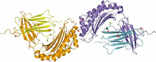
Structure of A24 with a telomerase peptide (VYGFVRACL) showing overall fold and contents of the AU. Complex 1 is shown as blue and cyan, with the peptide mostly blue. Complex 2 is shown as orange and yellow, with the peptide mostly orange. Ligands located in electron density are shown as red sticks (sulfate ions) and green sticks (glycerol molecules). This illustration was prepared with PYMOL 41.
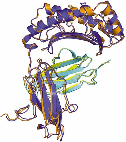
Superposition of A24 complex 1 (blue and cyan) and complex 2 (orange and yellow) shows a preserved fold for the protein. The peptides (shown as sticks) in each complex also retain conserved conformations with respect to the buried residues, but show significant differences around P4 and P6 due to the inherent flexibility of the exposed residues.
Peptide binding interface
The electron density around the VYG peptide in the two copies of the AU clearly revealed an extended conformation in the HLA binding groove (Fig. 3). The surface area buried by peptide binding was calculated as 736 Å2 and 737 Å2 for complexes 1 and 2, respectively. The peptide binding groove has been classified elsewhere into six pockets, A to F 21. The same nomenclature was adopted here and was used in the analysis below. The general features of the binding are similar to those observed in other peptide-HLA I (pHLA I) complexes. The peptide termini provide binding deep into the HLA I binding groove with many specific contacts between peptide main/side chains and HLA I groove residues (Fig. 4). Specifically, VP1 forms a close hydrogen bond with Y159 and a more tentative bond with E63 in the A pocket of the A24 molecule. This feature would suggest some importance for this residue in anchoring the peptide, although peptide screening of A24-compatible molecules suggests that V is not conserved at this position. Of more importance is YP2, which is conserved in virtually all observed A24-compatible peptides (Table 3), indicating that the hydrogen bond formed between the bulky aromatic side chain and H70 in the B pocket of the HLA I is vital for peptide stabilization at the N terminus of the peptide 22 (Fig. 5). GP3 makes a hydrogen bond with K66 in pocket D, but this residue is not conserved and is probably not vital for peptide anchoring. Similarly, strong hydrogen bonds are made between VP5 with Q156 in pocket C, and AP7 and T73 in pocket E. These ‘middle’ contacts are presumably less important for peptide binding in general as they represent the more variable residues in terms of A24 peptide presentation. LP9 is the other important anchor residue and forms hydrogen bonds with Y84 and T143 in pocket F (Fig. 5), allowing the non-anchor residues to bulge out of the HLA α1:α2 binding groove (Fig. 6). These contacts are vital for pHLA I stability and presentation to T cells via the TCR.
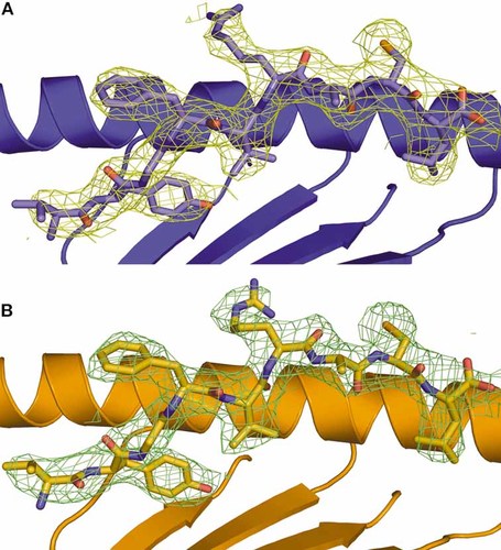
Electron density at 1σ contour level around the peptide of (A) A24 complex 1 (blue) and (B) A24 complex 2 (orange), showing the overall conformation of the peptide. P2, P5 and P9 point downwards into the groove, anchoring the peptide into place, whilst P4 and P6 extend out of the interface, creating an ‘M’-shaped conformation for subsequent TCR interaction.
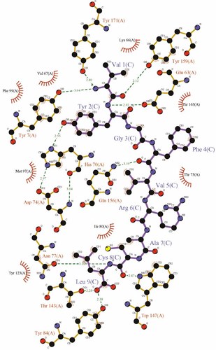
LIGPLOT 42 schematic diagram showing the various interactions of the peptide with A24 complex 1. Purple lines are peptide covalent bonds, orange lines are protein covalent bonds, dotted green lines are polar/H-bond contacts, open red arcs indicate a protein atom in a non-polar contact, and black spheres with radial red lines are the corresponding peptide atoms in a noncovalent contact. The major anchor residue interactions between YP2 and H70, LP9 and Y84, and VP5 and Q156 are visible here. The interactions in A24 complex 2 (not shown) are very similar.
|
Origin |
Residues |
Sequencea) |
|---|---|---|
|
TEL-hTERT |
(461–469) |
VYGFVRACL 43 |
|
TEL-hTERT |
(324–332) |
VYAETKHFL 43 |
|
HBV |
(756–764) |
KYTSFPWLL 44 |
|
HBV |
(117–125) |
EYLVSFGVW 44 |
|
HCV |
(1031–1039) |
AYSQQTRGL 44 |
|
CMV-P1 |
(100-/108) |
VYALPLKML 45 |
|
CMV-P2 |
(328-/336) |
QYDPVAALF 45 |
|
CMV-P3 |
(167–175) |
VYYTSAFVF 45 |
|
PSMA24–1 |
(298–296) |
GYYDAQKLL 46 |
|
PSMA24–2 |
(624–632) |
TYSVSFDSL 46 |
|
PSMA24–3 |
(227–235) |
LYSDPADYF 46 |
|
PSMA24–4 |
(606–614) |
KYADKIYSI 46 |
|
PSMA24–5 |
(178–186) |
NYARTEDFF 46 |
|
PSMA24–6 |
(74–83) |
LYNFTQIPHL 46 |
|
PSMA24–7 |
(565–574) |
FYDPMFKYHL 46 |
|
PSMA24–8 |
(699–708) |
KYAGESFPGI 46 |
|
PSMA24–9 |
(624–633) |
TYSVSFDSLF 46 |
|
Type I protein phosphatase |
(91–99) |
KYPENFFLL 29 |
|
Activated. Natural killer T cell peptide NK4 |
|
YYEEQHPEL 29 |
|
EBV |
(222–230) |
IYVLVMLVL 12 |
|
EBV |
(198–206) |
TYPVLEEMF 12 |
|
EBV |
(320–328) |
DYNFVKQLF 12 |
|
Survivin |
(80–88) |
AYACNTSTL 14 |
- a) Anchor Residue 2 – Y (23); Anchor Residue 5 – V (2), T (3), F (1), S (4), Q (2), P (2), A (1), K (1), M (1), E (1), N (2); Anchor Residue Terminal – L (13), W (1), F (7), I (2)
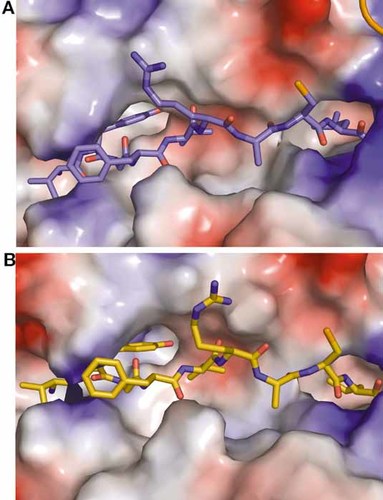
Peptide conformation in the A24 peptide binding groove. The vacuum electrostatic potential surface of the HLA is shown, based on Amber 99 charges, and the peptides are shown as sticks; (A) Peptide 1 (blue), (B) Peptide 2 (orange). The deep B binding pocket of A24 and the subsequent tight interaction with YP2 can be seen here. Also, the interaction between the terminal anchor residue, LP9, and the deep A24 F pocket is visible.
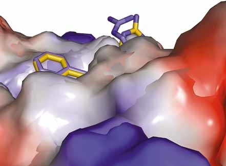
The vacuum electrostatic potential surface, based on Amber 99 charges, of A24 from the side. Only the side chains of residues FP4 and RP6 can be observed protruding outside the peptide binding groove, providing potential contact points for TCR interaction. The inherent flexibility at these positions, due to the exposure of these residues, can be observed here in terms of the conformational difference between the two complexes. The coordinates of the two complexes are superposed, as before. Complex 1 is shown in blue and complex 2 is shown in orange.
The peptide conformation is unusual in having a middle anchor point at VP5, a feature similar to that observed only in B8 HIV-Gag and A1 HIV-1 peptide complexes 23, 24. The peptide adopts an ‘M’-shaped conformation that sees the backbone of positions 3 to 7 twice rising out of and dipping into the groove at alternate residues. Anchor residues at GP3 and AP7 lock the peptide into place on either side of the prominently exposed FP4 and RP6 residues, which form the two tops of the ‘M'. The anchor residue at VP5 secures the peptide in the groove between the two exposed residues, forming the dip in the ‘M’ (Fig. 3). In other examples, there is a tendency for two adjacent residues to bulge out from the HLA I surface, e.g. P4 and P5 or P5 and P6, on a more exposed central bulge for TCR docking 21, 25, 26.
Projected TCR:pHLA docking
Like other pHLA I complexes, the bulge is also observed around the central residues of the peptide (Fig. 6). The two most prominent and probably most important residues for TCR interaction are FP4 and RP6, which make little contact with the HLA I binding groove, leaving them free to present their side chains conspicuously for TCR docking. FP4 is not as prominent as RP6, illustrated by the relatively higher thermal parameter (45–50 Å2 compared with 55–70 Å2 for the latter) indicating greater mobility. When the two copies of the peptide in the AU are superposed, the peptides show almost identical topology, with an RMSD of 0.26 Å for the Cα domains. However, slight reorientation of the RP6 side chain was apparent (Fig. 6), exploiting the free volume around it. Such flexibility could be involved in allowing a greater range of TCR to bind. In other A24-compatible peptides, the FP4 and RP6 positions are not conserved, in agreement with the notion that these residues are pivotal to the specificity of TCR recognition. CP8, although not as prominently exposed as FP4 and RP6, also makes little contact with the HLA I surface and might be involved in TCR docking. Furthermore, VP1, which is not conserved in other A24-binding peptides, could potentially contact the TCR as the N-terminal side chain points away from the HLA I surface (Fig. 3); however, it is equally possible that the side chain could simply be pointing out into the solvent region, away from the TCR interface.
Discussion
The crystal structure of A24 complexed to VYG provides insights into the peptide presentation of this highly abundant HLA I type. Like in other pHLA I structures, position P2 is highly conserved as an important anchor residue 27. Notably, at position P2, bulky aromatic side chains such as F and, more prominently, Y are found in all A24-compatible epitopes reported 22 (Table 3). Moreover, residues with bulky aromatic side chains are highly unusual as anchor residues at P2 in peptides binding to other HLA I, indicating the significance of the large, deep B pocket observed in A24. The interaction of H70 in the B pocket and an amino acid with an aromatic side chain at P2 is a key element for peptide anchoring and A24 stabilization. The importance of the YP2 anchor in this structure is emphasized by the buried surface area and shape complementarity statistics (data not shown). Also involved in the N-terminal peptide anchoring are residues VP1 and GP3 bound to HLA I pockets A and D, respectively, although contacts are far less extensive than observed for the heavily buried YP2 residue. P1 is more buried than in previously described pHLA I structures and its side chain is less likely to be important as a TCR contact point in A24, indicating a more involved function for pocket A in anchoring the N terminus of the peptide 28, 29. However, as anchor residues, P1 and P3 are less important than P2 and PC in A24, which is reaffirmed by the relatively high degree of amino acid variability at these positions (Table 3). At the C terminus, the large side chain of LP9 plays the most important role in locking the peptide into place. This is due to hydrogen bonds formed within the deep F pocket of the A24 binding groove. The residue for this position is markedly less conserved than in other HLA I examples 25, 30–32, although only amino acids with large hydrophobic side chains, such as L, W, F and I, are observed (Table 3). In addition to VP9, AP7 (pocket E) also acts as a C-terminal anchor. Between these two residues, a slight bulge occurs at CP8, creating a void around the reactive C side chain. Again, amino acid identity at theses residues is relatively heterogeneous and adds significantly to peptide diversity.
The most salient feature of this structure is the central peptide bulge, likely to be the dominant component of TCR docking and T cell recognition. The bulge has been observed in all previous pHLA I structures reported 33 and has been shown to be integral in TCR:pHLA I coupling 34. However, in other pHLA I structures, it is more usual for adjacent amino acids such as P4 and P5 to form the bulge 21, 25, 26. In A24, FP4 points away from the HLA I surface, but VP5 anchors the peptide back into the binding groove rather than being exposed. This allows RP6 to face away from the HLA I surface, giving the peptide an ‘M’-shaped conformation, thus providing a more unusual surface for TCR interaction. Whether this feature occurs in other A24-peptide complexes is unclear due to the variability of the P5 residue (Table 3).
A24 forms an almost identical 3-D fold as seen in previous studies of pHLA I structures, with a peptide binding groove in the HLA α1:α2 domain. The peptide itself is primarily anchored at the N terminus by an extremely conserved Y residue at P2 and at the C terminus by relatively conserved residues at P9, common with all 9-mer peptide HLA I binding. However, residues at P1, P3 and P7 are likely to play more prominent roles in anchoring the peptide to the binding groove, as these residues are more buried than in previous pHLA I structures reported. The projected marker residues for TCR recognition are, as in other pHLA I types, in the central portion of the peptide. However, in A24 VYG, the peptide forms an unusual and distinct ‘M’-shaped conformation; it will be interesting to ascertain whether other A24 peptide complexes share this characteristic feature and how it influences the mode of TCR docking.
Materials and methods
Generation of A24 and β2m expression plasmids
The A24 and β2 m expression plasmids were generated by QuickChange PCR mutagenesis (Stratagene) from pEX517, which contains A24 α chain residues 1–284, and JMB034B, which contains β2 m residues 1–100 under the control of the T7 promoter. A24 and β2 m sequences were confirmed by automated DNA sequencing (Lark Technologies).
Protein expression, refolding and purification
Of plasmid stock containing amino acids 1–284 of the A24 α chain, or amino acids 1–100 of β2 m, transformed into 20 µL of Rossetta DE3 competent E. coli cells, 1 µL was used to inoculate 1 L warm TYP medium (16 g/L tryptone, 16 g/L yeast extract, 5 g/L NaCl, 2.5 g/L K2HPO4) containing 100 µM ampicillin. The transformed cells were induced using 0.5 mM isopropyl β-D-thiogalactopyranoside, harvested by centrifugation, and the subsequent inclusion bodies were harvested by lysis in 20 mL lysis buffer (10 mM Tris, 10 mM MgCl2, 150 mM NaCl, 10% glycerol), sonication and treatment with triton wash buffer (0.5% Triton X-100, 50 mM Tris pH 8, 100 mM NaCl, 10 mM EDTA). The protein, in the form of inclusion bodies, was washed and then dissolved in guanidine buffer (6 M guanidine, 50 mM Tris, 2 mM EDTA, 100 mM NaCl). Prior to refolding, protein concentration was estimated using a Bradford reagent kit (Sigma-Aldrich) using BSA as standard.
Refolding of A24 VYG was carried out as described 35. Briefly, 30 mg/L α chain was mixed with 30 mg/L β2 m at 37°C and 4 mg/L synthetic peptide for 15 min. This was then added to cold refold buffer (50 mM Tris pH 8, 2 mM EDTA pH 8, 400 mM L-arginine, 0.74 g/L mercaptoethylamine, 0.83 g/L cysteine). The refold was allowed to mix at 4°C for at least 1 h before dialysis. Dialysis was carried out at 4°C for 2 days, changing the dialysis buffer once. The refold was then filtered and anion-exchanged using a POROS 50HQ column (Applied Biosystems) in 10 mM Tris pH 8, and then gel-filtrated into crystallization buffer (10 mM Tris, 10 mM NaCl) using a Superdex 200HR column (Amersham). The purity of each protein was measured using an SDS-PAGE 10% Bis-Tris gel.
Crystallization
A24 VYG was concentrated to 20 mg/mL in 10 mM Tris, 10 mM NaCl buffer. Crystal screens were initiated using Crystal Screen (CS)1 (Hampton research), CS2 and CS Cryo 1 buffers 1–48 with 0.5-µL drops of protein and 0.5-µL drops of crystallization buffer, using the hanging drop method. Plates were incubated at 291 K and analyzed after 24 h, 48 h and 1 wk. Crystals were observed in CS2 buffers 23 and 32 after 24 h. Crystals were flash-cooled in liquid nitrogen in Cryo loops and the working data set was collected from crystals grown in CS2 buffer 23 (1.6 M AmSO4, 0.1 M NaCl, 0.1 M HEPES, 10% dioxane).
Diffraction data collection and model refinement
Data were collected with the rotation method at Station 14.1 of the Synchrotron Radiation Source (SRS; Daresbury, UK) using an ADSC Quantum 4 CCD detector system. (Rigaku/MSC). The wavelength (λ) was set to 1.488 Å. The data set was collected from two crystals, where a total of 320 frames were recorded, each covering 1° of rotation. Reflection intensities were estimated with the MOSFLM package (http://www.ccp4.ac.uk/download.php) 36, and the data scaled, reduced and analyzed with the CCP4 package (http://www.ccp4.ac.uk/download.php) 37. Crystal data and relevant statistics are given in Table 1.
The refined model of the A6TCR:HLA-A2 TAX complex (Protein Data Base code 1AO7) was used as a search probe in AMoRe. The final fitted coordinates from AMoRe were checked for close contacts using the graphics programs ‘O’ (http://www.bio.net) 38. The model sequence was corrected prior to refinement with REFMAC5 (http://www.ccp4.ac.vk/download.php) 39. Manual adjustment of the model by visual inspection of the electron density maps was performed at various stages. Remaining positive density was filled, as appropriate, with solvent (ARP/wARP procedure in CCP4) or ligand molecules. The thermal parameters were allowed to refine, but were restrained to be similar to those of neighboring atoms (Table 1). The two pHLA I complex copies found in the AU were refined with medium non-crystallographic restraints applied. The latter graphics sessions for model adjustment were performed with COOT (http:/www.ysbl.york.ac.vk/∼emsley/coot/) 40. The final refinement statistics are listed in Table 2. The final coordinates were submitted to the Protein Data Base (code 2BCK).
Acknowledgements
We wish to thank Soad Melloul for technical assistance. D.K.C. is supported by an MRC studentship; G.F.G. and F.G. are supported by a grant from the Chinese Academy of Sciences (CAS) Knowledge Innovation Project Grant No. KSCX2-SW-227.
- WILEY-VCH
- WILEY-VCH
- WILEY-VCH
- WILEY-VCH
- WILEY-VCH
- WILEY-VCH


