Study on simulation of real-time hybrid model test for offshore wind turbines
Abstract
As an emerging energy source with great potential, offshore wind power is supported by development policies in an increasing number of countries. However, the performance evaluation of floating offshore wind turbine (FOWT) structures is challenging due to the complexity of wind and wave loads and the difficulty in reproducing such loading conditions for downscaled FOWTs in laboratories. In physical model tests of FOWTs, the Froude's similarity law is adopted for the foundation, while the Reynolds similarity law is adopted for the blades, thus there is an issue with uncoordinated scaling laws. The FOWTs real-time hybrid test uses loading device to simulate air loads, offering a new way to avoid scaling issues and reduce cost barriers. In this study, taking the 5 MW Braceless FOWT as the research object, a conceptual design of a real-time hybrid model test system for Braceless offshore wind turbines is proposed. Six sets of working conditions are set for simulation to study the motion and force performances of the hybrid system. The performance requirements of the Braceless structure for the loading device in the real-time hybrid test are quantified. Simulate different errors in the test to analyse the sensitivity of the response of the Braceless offshore wind turbine to various errors. The results show that the Braceless FOWT is relatively sensitive to motion and force errors. Due to the low-frequency characteristics of offshore wind turbines and external load, the delay error has relatively little effect. The method results in this paper can provide theoretical support and design information support for the implementation of real-time hybrid model tests in the future.
1 INTRODUCTION
With the intensification of the global greenhouse effect, offshore wind power, as an emerging field of clean energy, has huge energy production potential and has been widely supported and developed in various countries around the world.1-3 To better utilize high-quality offshore wind resources, the wind turbine capacity and the hub height of offshore wind power continue to rise, and the whole wind turbine structure tends to be large-scale. The process of going to far-reaching seas leads to a more complex and extreme marine environment.4 To better ensure the structural integrity and operational safety of offshore wind turbines during their service life, it is necessary to strengthen the research on the structural performance and coupling mechanism of offshore wind turbines in complex marine environments.5-10
Physical hydrodynamic model tests are still required in wave tank facilities to calibrate parameters used in the numerical models and evaluate and verify the performance of the current design of offshore wind turbines. Compared with the numerical calculations, offshore wind turbine model tests more accurately reflect the dynamic response behavior of the structure in the wind, wave, and current environments. Therefore, many numerical calculations need to be checked by taking the model test as the standard. As observed in practice, the model test is more controllable, convenient, time-saving, and economical. However, Froude's scaling law is usually used for model tests in wave tank installations to maintain the proportion of gravity to the inertial force. Froude's scaling guarantees the similarity of hydrodynamics on free surfaces, but it will lead to the mismatch same viscous effect due to the reduction in Reynolds number.11 Although the Reynolds number is often ignored in the ocean model tests, the related changes in the Reynolds number of aerodynamics pose a challenge to the floating offshore wind turbine (FOWT) test, because viscous forces after scaling are dominant in the upper wind turbine aerodynamics.12 Real-time hybrid testing is a promising and effective method to solve the above scaling incompatibility problem.13 The concept is shown in Figure 1. In general, computer simulations and physical mode tests are independent of each other. The hybrid model test applies simulation outputs to the scale model test through a hardware-in-the-loop method, so that the two processes can carry out data transmission, thus the efficiency and reliability of the mode test are greatly improved.

This method was used in the experiment carried out by Sauder et al.14-16 In this test, different actuators were controlled by the force distribution calculation program to realize the loading of multi-degrees of freedom (DOF) air load on the physical substructure. The test verifies the feasibility and correctness of the hybrid model test of the offshore floating turbines and has important guiding significance. This method was also applied to study the real-time hybrid test of the DeepCwind turbine.17-19 The multi-DOF cable-driven parallel manipulators (CDPM) was changed to a single DOF CDPM. The x-direction thrusts of wind load in front of and behind the nacelle were simulated by the length of cable expansion. There was a certain error between the test and numerical simulation results of platform surge movement. The multi-DOF turbines form a loading system through six small turbines controlled by electric servo motors. This method has been applied in the MARIN tank.20, 21 By adjusting the turbine speed to produce variable thrust and the influence of turbulent wind on the offshore floating turbine is simulated in this way, the results are compared with the simulation results. The real-time hybrid model test can accurately reproduce the influence of aerodynamic thrust and damping on the coupling system. The SHIVER project used two integrated linear actuators to control the two-dimensional motion of rigid piles,22 the structural characteristics of the model can be directly adjusted in the numerical substructure, which is very convenient. However, the error of the results in the above-mentioned part of the experiment is as high as 17%. We should realize that uncertainty errors tend to bring destabilizing effects into the real-time hybrid simulation (RTHS), causing large experimental errors or even failure.23-25
This study proposes a conceptual design for a real-time hybrid model test suitable for Braceless offshore wind turbines, sets the corresponding working conditions, and quantitatively analyzes the motion and force performances of the coupled system through the OPENFAST software. These results can provide reference data for the design and manufacture of the loading device. Then, the OPENFAST software was developed, errors of various factors were inserted into the motion and force of the top of the tower. The sensitivity of the Braceless FOWT overall structure to different errors was analyzed, and the quality requirements of the coupling system were studied. These results can provide theoretical support and design information support for the implementation of real-time hybrid model experiments.
2 THEORETICAL BACKGROUND
The real-time hybrid model test divides the part of the research object that is difficult to reproduce in the test site and has a clear response law into numerical substructures, uses numerical methods to solve and calculate. The parts that are of interest to the research and difficult to numerically simulate are divided into physical substructures, experimental studies are carried out on them. Numerical calculation results and physical test results are mixed with each other for real-time iteration, which in turn reflect the dynamic response of the overall structure. Compared with traditional offshore engineering platforms, offshore wind turbines are tall and flexible structures, and the aerodynamic load acting on the turbine impeller is transmitted to the floating platform through the tower, which has a greater impact on the motion response of the floating platform. The wave load and flow load mainly act on the floating platform, and also have a great influence on the dynamic response of the floating turbine. The relevant calculation theories of offshore wind turbines are mainly as follows.
2.1 Aerodynamic calculation theory
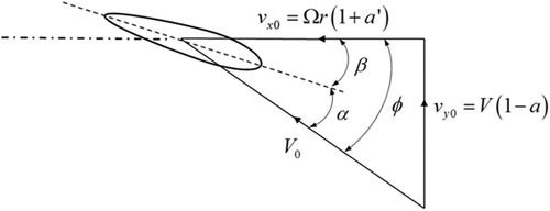
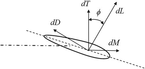
Blade element momentum theory26 comes from two theories, blade element theory and momentum theory. Betz momentum theory27, 28 assumes that the momentum loss in the plane of the impeller is mainly contributed by the work done by the plane airflow. Therefore, the induced velocity of the blade can be calculated through the momentum loss in the axial and tangential directions. The induced velocity changes the flow field in the wind turbine plane and then affects the aerodynamic load of the blade.
2.2 Hydrodynamic calculation theory
Potential flow theory29, 30 is used to calculate the hydrodynamics when designing marine structures. Potential flow theory considers the flow around a body to be incompressible, inviscid, and irrotational, with negligible surface-tension effects.
3 MODELING OF THE REAL-TIME HYBRID TEST SYSTEM
3.1 Numerical model of the Braceless FOWTs
3.1.1 Wind turbine model
The wind turbine model used in this paper was developed by the National Renewable Energy Laboratory (NREL). It is a conventional three-bladed, upwind, variable-speed, collective-pitch controlled horizontal axis wind turbine. Its main properties are listed in Table 1.31 The floating structures' properties are summarized in Table 2. The conceptual diagram is shown in Figure 4.
| Parameter | Value |
|---|---|
| Rated power | 5 MW |
| Rotor orientation | Upwind |
| Rotor, Hub diameter | 126 m, 3 m |
| Hub height | 90 m |
| Cut-in, rated, cut-out wind speed | 3 m/s, 11.4 m/s, 25 m/s |
| Cut-in, rated, rated rotor speed | 6.9 rpm, 12.1 rpm |
| Overhang, shaft tilt, precone | 5 m, 5°, 2.5° |
| Rotor, nacelle, tower mass | 110 t, 240 t, 347.46 t |
| Tower top, diameter, wall thickness | 3.87 m, 0.019 m |
| Parameter | Braceless |
|---|---|
| Semi | |
| Water depth (m) | 100 |
| Freeboard (m) | 20 |
| Draft (m) | 30 |
| Submerged volume (m3) | 10,517 |
| Floater steel mass (kg) | 1,686,000 |
| Total mass (Including WT) (kg) | 10,780,000 |
| COG (x, y, z) (m, m, m) | (0,0, −18.9) |
| Ixx w.r.t. COG (kg*m2) | 10,650,000,000 |
| Iyy w.r.t. COG (kg*m2) | 10,650,000,000 |
| Izz w.r.t. COG (kg*m2) | 8,412,000,000 |
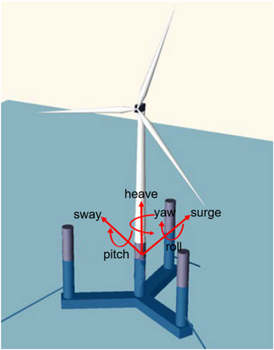
The Braceless semisubmersible platform is mainly composed of three side columns and one central column. It is noted that the Braceless semisubmersible FOWT is a symmetrical structure with NREL 5 MW wind turbine on the centre column. Three pontoons are used to connect the central column and side columns. More detailed information on Braceless semisubmersible FOWT can be found in Luan.32
3.1.2 Mooring systems
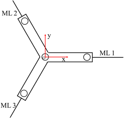
The mooring system of Braceless semisubmersible FOWT consists of three catenary mooring lines that are positioned at 120° between the mooring lines (as shown in Figure 5). Each mooring line is attached to the outer columns of the semi at a water depth of 18 m.
3.2 Principle of real-time hybrid test for FOWTs
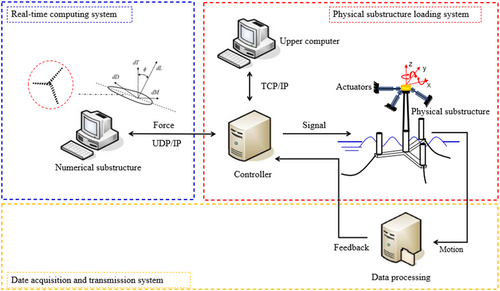
The real-time hybrid test in the wave tank is to replace the upper wind turbine with numerical substructures to solve the aerodynamic load generated by the wind turbine in the wind field and remain the lower tower and platform as physical substructures. Then the aerodynamic load is applied to the physical substructure through the loading system, and the physical model moves under the action of external forces. The model motion is measured in real-time by the sensoring system and transmitted to the numerical substructure. The numerical substructure calculates the aerodynamic load in the next time step according to the returned data, and cycles back and forth to realize the closed-loop data interaction. The advantage of this method is that the Froude similarity is used to scale down the model, and the force of the wind turbine is solved by the numerical program, which solves the complexity of the scale contradiction problem of the wind turbine blade and reproduces the aerodynamics well. There is no need for a specific wind tunnel test site, leading to higher practicability. This method focuses on the hydrodynamic performance of the FOWT platform under the action of wind. The system diagram is shown in Figure 6.
3.3 Simulation method
In this study, the OPENFAST software is used to study the real-time hybrid model test of the offshore wind turbine tank using numerical simulation. The aerodynamic load is solved by blade element momentum theory (BEM), the tower is modeled by finite element method (FE), the platform is modeled by structural dynamics method (SD), the mooring system is solved by catenary theory (CT), and the hydrodynamic load is solved by potential flow theory (PFT). By setting different working conditions, the kinematic and mechanical properties of the overall structure of the Braceless FOWT are obtained, and the performance requirements of the Braceless structure for the loading device in the real-time hybrid test are quantified. The secondary development of OPENFAST software is carried out, and the noise error and time delay error are inserted into the process of wind load transmission to the tower, and the noise error is inserted into the motion of the top of the tower. This strategy is used to simulate the background noise error of the loading device, the delay error of the loading device and the noise error of the sensor in the real-time hybrid model test. The sensitivity of Braceless FOWT overall structure to different errors is analyzed to better guide the physical model tests to be carried out. The Simulation method is shown in Figure 7.
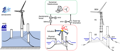
Four parameters (maximum displacements, maximum velocities, maximum accelerations, maximum forces and moments) are selected to describe the kinematic and mechanical of the Braceless FOWT real-time hybrid test, and to quantify the performance requirements of the test system for the loading device. It can assist in the design of multi-DOF loading devices and put forward requirements for the data monitoring system in the test.
The three most important error parameters (error tolerances for motion tracking; error tolerances for force actuation; acceptable latency levels) are selected to reflect the effect of different errors of Braceless FOWT real-time hybrid test. Corresponding errors are inserted into the tower top coupling point and the tower top motion in the time domain simulation, and the sensitivity of the real-time hybrid model test to different error parameters is studied (Table 3).
| Parameter | Braceless semi |
|---|---|
| Mooring line length (m) | 891.6 |
| Mooring line type | Spiral rope |
| Number of mooring lines | 3 |
| Equivalent axial stiffness, N | 3.08E9 |
| Number of mooring lines | 3 |
| Mass per unit length (kg/m) | 115.00 |
| Pretension (kN) | 1190.0 |
| Diameter of mooring line (m) | 0.1365 |
| Fairlead for ML1 (x, y, z) (m) | (43, 0, −18) |
| Fairlead for ML2 (x, y, z) (m) | (−22.1, 38.3, −18) |
| Fairlead for ML3 (x, y, z) (m) | (−22.1, −38.3, −18) |
| Anchor point of ML1 (x, y, z) (m) | (917.0, 0, −100) |
| Anchor point of ML2 (x, y, z) (m) | (−458.5, 794.1, −100) |
| Anchor point of ML3 (x, y, z) (m) | (−458.5, −794.1, −100) |
| Clump mass (volume/m3) | - |
| Clump mass (weight/kg) | 15,000 |
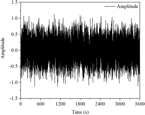
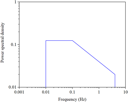
White and pink noise spectra are generated by the Box-Muller method, where 0.01–0.1 Hz is constant energy white noise and 0.1–4.0 Hz is pink noise, whose energy is inversely proportional to the square root of frequency. Since the rotor frequency in the upper part of the offshore wind turbine structure is low, the influence of high-frequency noise is not studied here. The time histories of noise is shown in Figure 8, the noise spectrum is shown in Figure 9.
3.4 Environmental conditions
A total of six wind and wave environments are set up for this study, corresponding to the below-rated value, at-rated value and above-rated, as shown in Table 4. Wind and waves go in the same direction. The turbulent wind file is selected according to the IEC standard, and different turbulence model curves are selected, which are generated by the TurbSim software according to the Kaimal spectrum. Waves are defined by the effective wave height, Hs, peak period, Tp, and peak shape parameters, , of the JONSWAP wave spectrum.33
| Load case | Hs (m) | Tp (s) | γ | Um (m/s) | TI (%) |
|---|---|---|---|---|---|
| 1 | 0.96 | 7.04 | 1.5 | 8 | 20.3 |
| 2 | 1.21 | 7.3 | 1.6 | 11.4 | 17.0 |
| 3 | 2.45 | 8.48 | 1.7 | 20 | 14.4 |
| 4 | 8 | 12.7 | 2.75 | 8 | 20.3 |
| 5 | 8.5 | 13.1 | 2.75 | 11.4 | 17.0 |
| 6 | 9.8 | 14.1 | 2.75 | 20 | 14.4 |
4 ACTUATION PERFORMANCE REQUIREMENTS
According to the load conditions in the working condition Table 4, simulate the wind and wave conditions of the full-scale 5 MW Braceless FOWT. According to different random numbers, each working condition is simulated six times. To remove the transient effect, the simulation is performed for 1 h and delete the results of the first 300 s. Since this simulation is a real-time hybrid test of a wave tank, the relevant parameters at the top of the tower are selected for analysis, and the full-scale motion response and dynamic characteristics of the real-time hybrid test of offshore wind turbines are studied.
4.1 Motions requirement
Aiming at the motion response of the Braceless platform, three parameters of the maximum displacement, the maximum velocity and the maximum acceleration at the coupling point at the top of the tower are selected to reflect the performance indicators that the loading and measurement system needs to achieve in the real-time hybrid test of the offshore wind turbine. Surge displacement of the Braceless platform at the top of the tower under different working conditions is shown in Figure 10. The height represents the average maximum value under different working conditions, and the error bars are the standard deviation under different working conditions. The maximum pitch angle is shown in Figure 11, the maximum surge rate is shown in Figure 12, the pitch rate is shown in Figure 13, and the maximum acceleration of surge and pitch are shown in Figures 14 and 15, respectively.
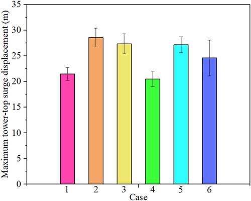
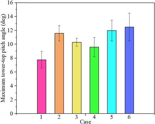
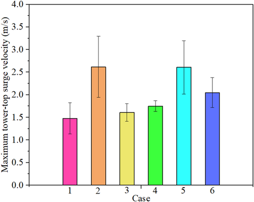
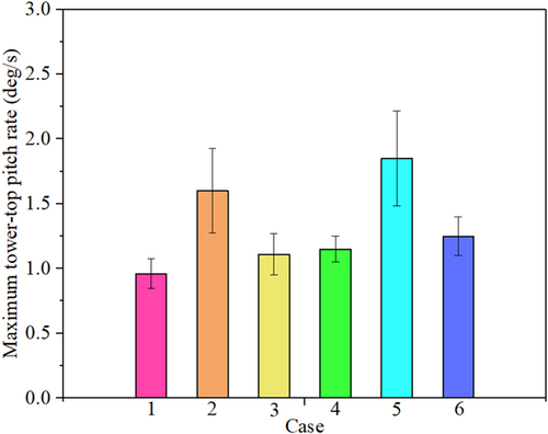
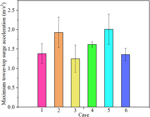
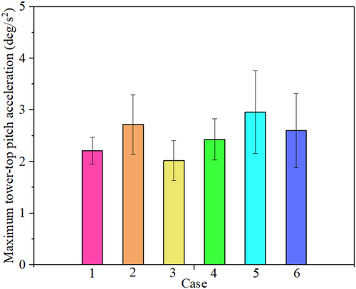
The above statistical results can provide a reference for the movement performance of the Braceless FOWT in the real-time hybrid model test in a wave tank, and also provide information support for the design and production of the loading device. The change of the wave load will lead to an increase in the overall value of the tower's top parameters, but the effect is relatively small, mainly affecting the changes in velocity and acceleration because the coupling point is selected at the top of the tower. The wave load change is more consistent with the maximum speed and is reflected in the pitch angle. The maximum value of statistics will be listed in Section 4.3.
4.2 Forces requirement
Similar to the data processing method of motion response, the maximum value and error of force and torque under different working conditions are processed. The force-related results are organized into the maximum mean and standard deviation, which can reflect the performance requirements of the loading device in the real-time hybrid model test of the Braceless FOWTs. The maximum surge direction force and pitch moment are shown in Figures 16 and 17.
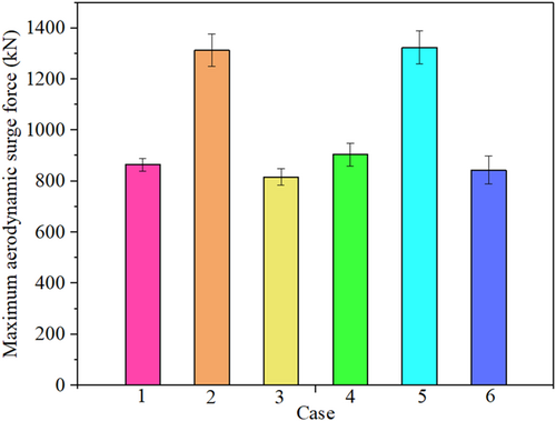
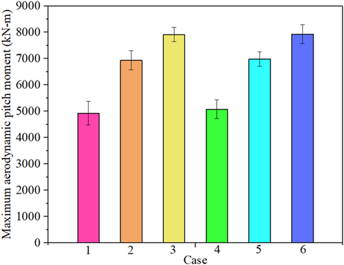
The above results provide a reference for the mechanical properties of the loading system in the Braceless FOWT real-time hybrid test. The change of the wave load will lead to an overall increase in the values of the tower top force and pitching moment, but the effect is relatively small, and the reason is consistent with the motion response. In addition, selecting the top of the tower as the coupling point has lower requirements on the mechanical properties of the loading system, and the maximum value of the mechanical properties results is relatively stable.
4.3 Estimation of requirements
The above results show the correlation results of the motion and mechanical properties of the two most important degrees of freedom, surge and pitch, at the top of the Braceless FOWT tower under different operating conditions. According to the same data processing method, the relevant parameters for other degrees of freedom are listed in Table 5. These values reflect the performance values of each DOF at the top of the tower under different working conditions, and can provide a reference for the design and manufacture of the multi-dimensional loading system for the real-time hybrid model test in wave tank. Other load cases could have requirements exceeding these, especially in the case of different wind and wave directions or turbine yaw misalignment.
| Requirement type | Surge | Sway | Heave | Roll | Pitch | Yaw |
|---|---|---|---|---|---|---|
| Displacement range (m, ◦) | 30.4 | 2.81 | 4.60 | 2.7 | 14.5 | 10.5 |
| Max. velocity (m/s, ◦/s) | 3.30 | 0.70 | 1.41 | 0.5 | 2.27 | 0.47 |
| Max. acceleration (m/s2, ◦/s2) | 2.41 | 0.69 | 0.76 | 3.97 | 4.21 | 0.35 |
| Max. force, moment (kN, MN-m) | 1376 | 154.8 | 211.1 | 10.36 | 8.20 | 8.02 |
5 SENSITIVITY ANALYSIS OF DIFFERENT ERRORS FOR BRACELESS FOWT
In this section, the secondary development of OPENFAST software is carried out. Through the time series simulation strategy, the error and time delay error are inserted in the process of wind load transmission to the tower, and the error is inserted into the motion amount of the tower top. This strategy is used to simulate the different errors that exist in real-time hybrid model experiments. Then, different error sensitivity analysis is carried out to quantify the influence of different errors on the Braceless FOWT. The analysis results can better guide the real-time hybrid model test of offshore wind turbines, and can also avoid damage to the equipment caused by the instability of the test system.
As a response parameter in the global coordinate system, the motion of the platform's pitch and surge directions can fully reflect the influence of the wind turbine on the structure. The tower base bending moment is particularly sensitive to wind thrust, and small errors can also be reflected by the tower base bending moment. Therefore, the platform surge (Surge refers to the displacement of offshore wind turbine platform in the X direction), platform pitch (Pitch refers to the torsion of offshore wind turbine platform in the X direction) and fro-aft bending moments of the tower base of the platform are selected as the analysis objects, and other motion responses of the platform are more dependent on the design of the support structure and are relatively slow to change in air loads. To control the variables and accurately study the effect of errors in the real-time hybrid test of the tank, load condition 5 with more abundant wave conditions in Table 4 is used as the loading condition, which can fully reflect the sensitivity of the hybrid coupling error.
Errors and time delay error are inserted into the process of wind load transmission to the tower, and the noise error is inserted into the motion of the top of the tower to study the sensitivity of real-time hybrid experiments to different errors. The amplitude of the error is the abscissa value of different sensitivity errors, the average value is 0, and the frequency range can refer to Figure 9.
Inserting errors into the tower top motion of the Braceless platform, the relative RMS differences in platform surge (abbreviated as “surge” in the plot legends), platform pitch (abbreviated as “pitch” in the plot legends) and tower-base fore-aft bending moment (abbreviated as “moment” in the plot legends) are shown in Figure 18. The error is inserted in the platform tower top force, the RMS of the relevant channel is shown in Figure 19. Inserting the delay error, the associated channel RMS is shown in Figure 20. The relative RMS error chosen in this paper is a measure that compares the results through time series and accumulates the results, which is very sensitive. The comparison of the time series results with the RMS error level of the tower base moment at 10% is shown in Figure 21, which is a fabulous demonstration of this.
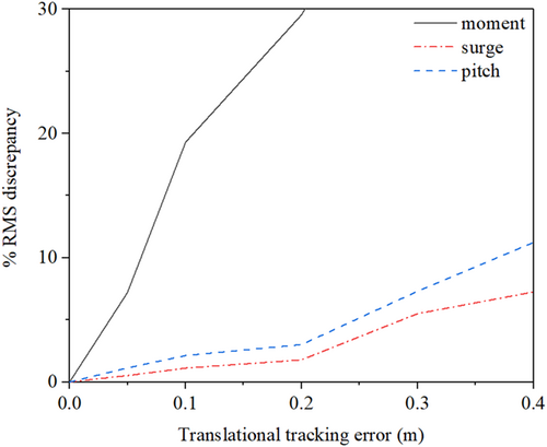
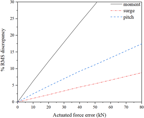
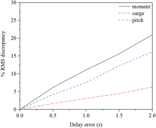
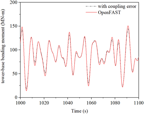
From the analysis of the above results, it can be seen that the error inserted in the motion response will cause the sensitivity to fluctuate greatly, which may be related to the change in the position and speed of the wind turbine in the wind field. The sensitivity to force error increases linearly, possibly with this error acting directly on the tower foundation bending moment through the tower structure, rather than through other mass-related quantities. The effect of time delay error on the overall result is relatively small, and it may be resulted from the low-frequency characteristic of offshore wind turbines and external load. Also because of this coupling and division method, the load at the lower tower base comes from the structural vibration, rather than the direct action of the air load, so it is relatively insensitive to delay.
6 CONCLUSIONS
- 1.
Statistical results from the simulation quantify the motion and force requirements in real-time hybrid model testing of Braceless FOWT. These results provide a reference for future implementation and provide design information support for sensor measurement and actuator loading performance.
- 2.
The real-time hybrid model test in a wave tank, the bending moment at the tower base is relatively sensitive to the error of force and motion. The surge and pitch direction responses of the platform are less sensitive to several errors, and it is suggested that the relevant research selects the tower foundation bending moment as a parameter to quantify the effect of the error.
- 3.
The force error acts directly on the tower base bending moment through the tower structure, rather than through other mass-related quantities, resulting in a linear increase in his error sensitivity. Delay errors have relatively little effect on the overall result and may be due to the low-frequency characteristics of offshore wind turbines and external load. The substructure division method adopted in this paper makes much of the dynamic loading at the tower-base comes from structural vibrations of the turbine rather than direct transmission of aerodynamic forces and is, therefore, unaffected by delay in the aerodynamic loading.
- 4.
In the real-time hybrid model test of offshore wind turbines, the level of sensitivity to different types of coupling errors strongly depends on the inertial and kinematic characteristics of the platform structure design.
ACKNOWLEDGMENTS
This research was funded by the National Natural Science Foundation of China (Grant no. 52071058 and 51939002). This paper is also partially funded by the Central Guidance on Local Science and Technology Development Fund of Shenzhen (2021Szvup018) and the Open Research Fund of Hunan Provincial Key Laboratory of Key Technology on Hydropower Development (PKLHD202003).
CONFLICTS OF INTEREST STATEMENT
The authors declare no conflicts of interest.


